Final Project: Design of an Electric Vehicle
AIM
MATLAB MODEL OF ELECTRIC CAR
OBJECTIVES
To design electric car model which uses battery and a dc motoe by choosing suitalble powertrain blockset.
system level cofigurations and Model Parameters
To explain the results an to conclude.
INTRODUCTION
All-electric vehicles (EVs), also referred to as battery electric vehicles, use a battery pack to store the electrical energy that powers the motor. EV batteries are charged by plugging the vehicle in to an electric power source. Although electric production may contribute to air pollution, the U.S. Environmental Protection Agency categorizes all-electric vehicles as zero-emission vehicles because they produce no direct exhaust or tailpipe emissionsBoth heavy-duty and light-duty EVs are availabe commercially. EVs are typically more expensive than similar conventional and hybrid vehicles, although some cost can be recovere throgh fuel savings
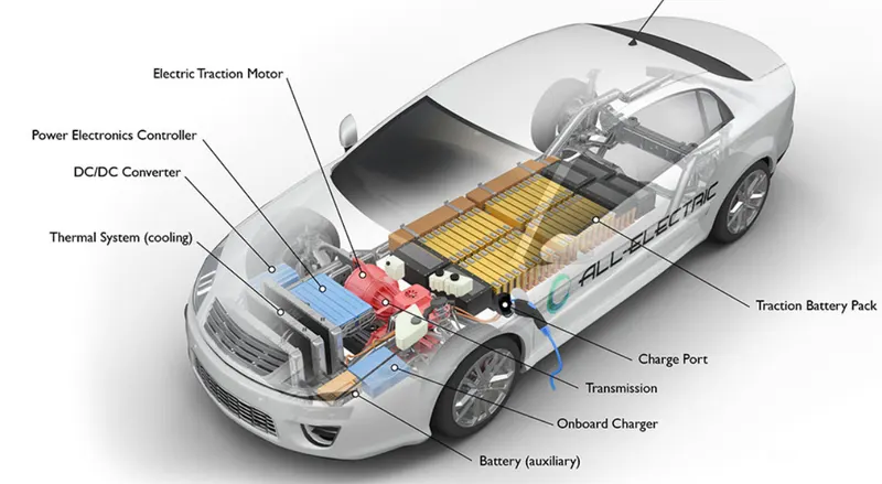
The base of any car is the battery. As told earlier, the battery used for this car is very expensive. By using lead acid batteries, the weight of the car increases a lot (>>1000 pounds). As the number of batteries range from 50 to more, they occupy a lot of space as well. They generate lesser driving powers comparing to gasoline cars. After a long drive, they need at least ten hours to get recharged completely. Apart from the battery used for the car mechanism, there is also an additional 12 V battery on board. This is needed to provide power for other components like wipers, radio, and air conditioner and so on. But the extra expense comes when you have to recharge the battery. You will need a 300V Dc to 12V DC converter.
As told earlier we need 300V DC to drive the AC motor. This rating is converted to 240V AC and is sent to the motor with the help of the converter. This can only be done using a set of transistors, which will convert the DC signal into sine waves rapidly. Thus when the accelerator is fully pressed, the controller produces almost 96 V to the motor. If the accelerator is released, the controller delivers 0V. Thus the controller stands as a buyer of power from the battery and giver of power to the motor. As the accelerator is pressed in different modes, the controller is supposed to give an output power accordingly. So, variable potentiometers are connected between the accelerator and the controller, so that variable, but proportional power can be delivered to the motor. But, if the potentiometer goes wrong the result can be fatal. So, as a safety measure, there are two potentiometers connected to the accelerator. If both show equal value, then the controller proceeds. If they are different, the controller stops working. The greatest disadvantage of this is that the whole car stops working if a single potentiometer goes wrong. In most of the cars, the controller is just a normal switch with an ON position while accelerating and an OFF position while decelerating. But, this is difficult for the driver as he will not get a flow. Thus the controller acts as a pulsator. It notices the value of potentiometer and rapidly switches the proportional power to the motor.The motors used in electric cars can be AC or DC. Mostly DC motors are preferred than AC motors because they are simple to configure and are not at all expensive. For AC motors 3-phase motors have to be used, running at 240V AC. DC motors, on the other hand requires only (96-192)Volts. DC motors can also be overdriven for a short period of time.
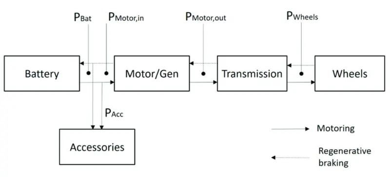
An Electric Car is an automobile by itself and consists of many components and a large cluster of wires connecting them all. But there are few basic bare minimum materials for an Electric Car which is shown in the block diagram below.
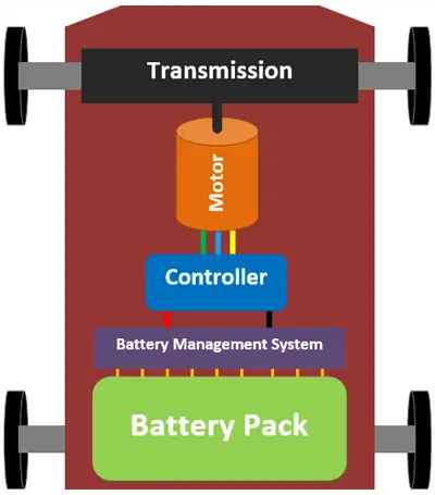
The Engine of a conventional IC Engine Car is replaced by an electrical Motor and the fuel tank is replaced by the Battery Pack. Of all the components only the Battery Pack and Motor alone contributes to about more than 50% of the total cars weight and the price. As you can see the Battery Pack, Battery Management System (BMS) Controller, Motor and the Transmission unit forms the major components in an EV.
Vital Parts of an Electric Car
The Battery Pack is the fuel source of the car, since there are hundreds of cells arranged to form a battery pack a special circuit is required to monitor these cells, this circuit is called as the Battery Monitoring circuit. The DC voltage from battery cannot be used to drive a motor so we need the controller which drives the motor, and the Transmission system transfers the rotational energy from motor on to the wheels through some gear arrangements. Let’s look into each Part in details to understand more on EV’s.
EV Batteries
Batteries are the fuel source for Electric Cars, but it is also important to know that batteries are not the only source of fuels. There are other alternatives to power an EV like a Fuel cell or super capacitors but both of them are still in development stage and no commercial cars on the road use them. So let us focus only on Battery Operated EV in this article.
The first think you should know about batteries in EV is that, unlike your mobile phone which has only one battery EV’s are powered by hundreds if not thousands of batteries joined together as a pack. To give you an idea the Tesla has 7000 batteries and the Chevrolet spark has 600 Batteries inside them. The complete battery anarchy consists of the Cell, Battery Module and Battery Pack.
Cell
The cell refers to a single battery. There many different sizes and shapes for a cell based on the chemistry. Most commonly used chemistry is the Lead-Acid Batteries and Lithium Batteries. These batteries are available in many different shapes like cylindrical, Coin, Prismatic and Flat type the voltage rating of the cells (per cell) will be anywhere from 3.7V for a lithium batteries and a maximum of 12V for Lead-Acid batteries. But, as you might have guessed this voltage is not enough to run an electric car. The Tesla for example has a battery pack voltage of 356 Voltas and even for a normal electric bi-cycle we need a minimum of 36V so how do we get this higher voltage from lithium cells that are only 3.7V?
Battery Module
So to get the higher voltage from 3.7v lithium cells, battery packs are used which are formed by combining more than one battery together. When two batteries are connected in series their voltage ratings is added and when two batteries are connected in parallel their Ah rating is added. For example assume we have 3.7V 2000mAh Lithium batteries. If you connect two of these in series the resulting system is called a module and this module will have 7.4V 2000mAh. Likewise if we connect two of these in parallel the resulting module will be 3.7V 4000mAh.
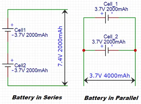
A single lithium cell voltage and Ah rating is not enough to drive an EV, so these cells are connected in series and parallel configuration to increase the resulting system voltage. This pack is called as a module. For people who are new to batteries the termAH might be confusing there are lot of such parameters related to batteries which we will cover in a separate article. For now you can think of Ah as the fuel range of an EV more the Ah more the mileage we can get out of the EV.
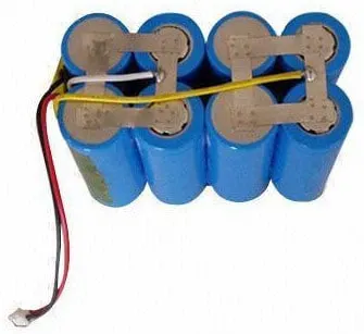 Lithium Battery Module
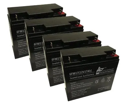 Lead Acid Battery Module
Battery Pack
Once the system Voltage and Ah rating is obtained by combining various modules in series and parallel configuration this set-up should be placed inside the EV. But it is not so easy; the reason is -its complexity. Lithium cells are unstable in nature any mishap like short circuit or excess charging or discharging can make there batteries get very hot leading to fire or explosion. So the voltage current and temperature of each cell should be monitored for a safe operation. The duty of monitoring the cells during the charging and discharging procedure is given to the circuit called Battery Management system or BMS for short.
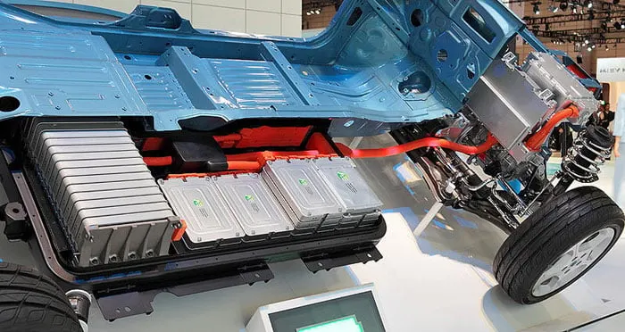 So, once the battery modulus is ready it should be connected to the BMS and a cooling system for safe operation of battery. The complete set-up is kept in a steel casing to prevent mechanical damage. This complete arrangement along with the BMS, cooling system casing and the battery modules all together is called as a Battery Pack of a car. These packs will normally be big and occupy the entire floor areas of an EV as shown in the picture below, This image is of the Nissan Leaf cut half way for you to give an idea.
Battery Management System (BMS)
Now that we have known about Batteries in EV the follow up would be to know about battery Management system. A BMS is like the brain or caretaker of batteries, as we saw earlier there are many batteries in an EV and each battery has to be monitored to ensure safety. For Lead Acid batteries BMS is not mandatory although some people use it but for Lithium cells due to its unstable nature BMS becomes essential.
Almost all lithium cells come with their own protection circuit if they are used in consumer electronics. This is because if they are not handled properly, like overcharging or over discharging then the battery would get hot and might even burn. The circuit simply monitors the cell voltage or current and breaks the connection to the load if it exceeds safe limits.Every BMS measures only three vital parameters of the battery which are the Voltage, current and Temperate of the cell. It constantly compares these values with safety limits and disconnects the load if they exceed the threshold values. Apart from safety purpose the BMS is also used for some computational purpose, like measuring the SOC and SOH of a battery.
SOC stands for State of Charge and SOH stands for State of health. Unlike an ICE Car the amount of fuel left in the battery cannot be measured by directly look at it. Some people even think that measuring the voltage across the terminals of the battery can give you the battery capacity, well it’s not true and it is not that easy. Similarly SOH gives the life expectancy of the battery. Both SOC and SOH are vital information for a consumer since SOC tells you how far you can drive before recharge and SOH tells you when it’s time to replace your batteries. It is the duty of the BMS to measure both these parameters.
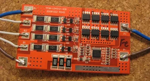
BMS circuits are often complex, a simple 4 Cell Lithium BMS is shown in the picture below. Imagine the BMS of a car that has to monitor around 7000 cell.
Electric Vehicle Motors
While batteries are the fuel tanks of an EV, the motors are the Engines of them. There are many types of Motors used in EV and the one used for Scooters and bikes is totally different form the one that is used in cars. Let’s have a quick look on the commonly used ones that are the BLDC motors, Brushed DC motors and AC Induction Motor. A more detailed article on EV motors will be covered later.
BLDC Motors: BLDC Motors have been the choice for EV’s from its origin in 1900. Even today it is commonly used in Electric cycles and scooters. BLDC stands for the brushless dc motor, these motors have a constant torque and fast response making it suitable for automotive applications. Apart from EV’s these motors are also used in wipers, power windows etc. The BLDC motor for EV can again be classified into the following two types
BLDC Hub Motors
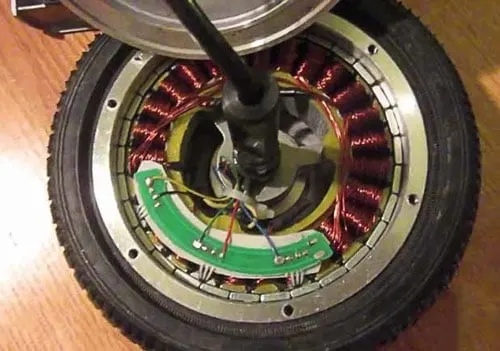
In BLDC Hub type motor, the rotor of the magnet is the wheel itself, meaning there is no need of coupling arrangement since the rim of the wheel forms the motor. These motors are also called as the BLDC out runner motor. Advantage of this type of motor is that there is less mechanical loss and since there is no transmission unit cost and weight is reduced. Downside is that we cannot have gear ratio of high power motors due to size limitations. A BLDC hub motor of scooter is shown below. Almost all electric cycles and scooters you find on road uses such type of motors.
BLDC In-runner Motors: Another type of BLDC motors are the In-runner types. They are used in applications where a transmission unit is required. They are normally coupled along with a differential for 3-wheeled or 4-wheeled EVs. These motors look like normal motors with a shaft and the shaft rotates when the motor is powered. An In-runner type Motor of an E-rickshaw coupled with differential is shown below.
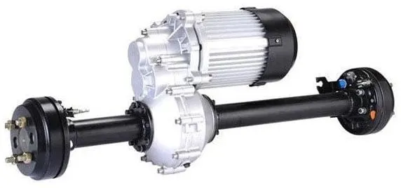
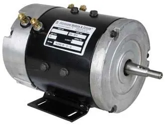
Brushed DC motors: The Brushed DC motor also known as DC series motor was the preferable choice for all old Electric cars. These motors provide a lot of torque which could easily give a sporty feel to the EV. The pull/pick-up of the EV would be almost at par with an average conventional car that these motors were used by drag racers during then. But now after 2008, these motors are not much in use any longer the reason is DC motors cannot provide a constant torque under a varying load. Meaning cursing or climbing a hill with the car will be difficult. Also DC motors cannot start without a load that is it cannot self start due to its high initial current which might damage the motor itself. Today these motors are used in Golf carts commonly a picture of the same is shown below
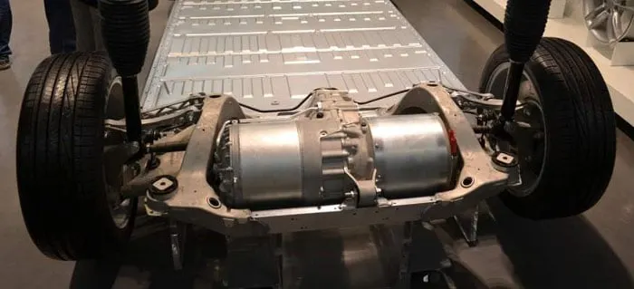
AC Induction Motors: Most Modern day Electric cars like the Tesla uses an AC Induction motor. The Tesla model S for instance uses a 3-phase AC Induction Motor. Well you might have already guessed it because the company itself is named after Tesla who invented the three phase AC Induction motor. The reason why these motors are selected is that they do not have permanent magnets within them and thus low cost. It also has good life since there are no magnets, magnets would lose their tendency in day course. The downside of the motor would be that it is hard to control the speed and torque of the motor and advanced circuitries are required. Below is the image of Tesla Model S front wheel, taken from Wikipedia.
Controller
There is a very good chance that this question already struck you. We know EV runs on battery which are DC powered and we have motors that run on three phase AC. How will both of these work together? This job is taken car by the Controller, from a basic bi-cycle till a Tesla Roadster every EV has its own controller that converts the DC voltage from the Battery to a suitable level for the Motors to run. It also controls the speed of the motor.
The controller gets all the inputs form the user like the amount of throttle (acceleration), breaks pressure, driving mode etc and controls the speed of the motor accordingly. If motors are considered to the muscle of a car, controller is its brain. A controller is often a generic term and it might include other circuits like a DC-DC converter, Speed controller, Inverter etc. The DC-DC converter is used to power all the peripherals of the car like the infotainment system, Headlights and other low level electronic devices.
Apart from this the controller also takes care of regenerative braking. It is the process of converting kinetic energy into electric energy. That is when the EV runs down a slope the motor are rotating freely due to the kinetic energy, at this situation the motors can be made to act as a generator so that the power thus obtained can be used to charge the batteries. Most modern day EV’s have this but its performance and functionality is still debatable.
EV Chargers
Another important component in an EV which requires advancement is the Chargers. An average E-Car takes a minimum of 5 hours to get charge that combined with its very low mileage becomes a disaster. An average American drives more than 50km per day, in this scenario an EV which gives a rage of 90km for full charge has to get charged almost every day. This makes the charges a most used component.
It gets plugged into the AC mains and converts the AC to DC to charge the batteries. But there are more to add to it. Charging is a process in which the batteries and charger should coexist you cannot push current inside a battery if the battery is not ready to accept it. There are many types of chargers; the most common types are discussed below.
Level 1 Charger: These are the most basic chargers and it is probably the one that you get along with your car. They take a long time to charge the batteries since they operate in 120V AC, They convert this 120V AC to DC and use it to charge the batteries. The current rating of the charger will also be low somewhere near 8-10 A, this means you will be sending less current and thus taking a long time to charge your batteries overnight. On the positive side, this method improves the life cycle of the battery since our charging current is less.
Level 2 Charger: These are a bit faster that Level 1 charger, it depends on the manufacturer to provide you with Level 1 or Level 2 charger. Level 2 chargers operate on higher voltages like 240V or above and also have high current rating near 40A to 50A. This makes the car to get charged faster.
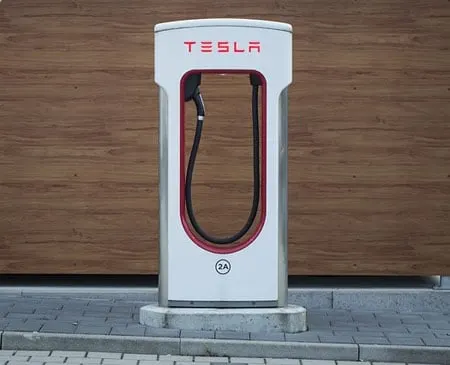
Level 3 chargers: Level 3 chargers are the game changers, this are also called as the super chargers or fast chargers. They can charge your car to 60% of its total capacity within 30 minutes. The downside is that since it is pushing a lot of current inside your battery like 100A for a Tesla the batteries inside would feel like taking a crash course all year. So eventually the life of the battery is reduced. Also most superchargers do not charge the batteries till 100% since more time will be required to charge the battery from 80% to 100%. A super charger station of Tesla is shown below.
Flowchart of design of electric vehicle
-
Predict the engine torque and fuel consumption that a vehicle requires to achieve desired speed and acceleration for a given gear shift reference.
-
Produce realistic velocity and shift references for closed loop acceleration and braking commands for vehicle control and plant models.
-
Study, tune, and optimize vehicle control, system performance, and system robustness over multiple drive cycles
LONGITUDINAL DRIVER
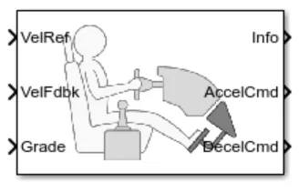
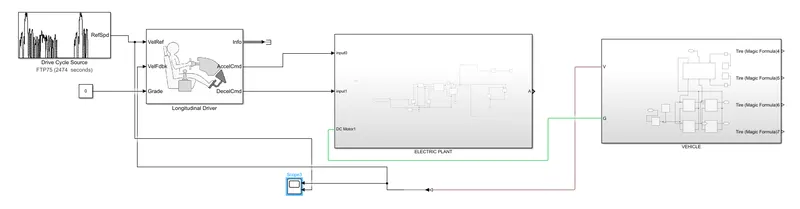
The Longitudinal Driver block implements a longitudinal speed-tracking controller. Based on reference and feedback velocities, the block generates normalized acceleration and braking commands that can vary from 0 through 1. You can use the block to model the dynamic response of a driver or to generate the commands necessary to track a longitudinal drive cycle.
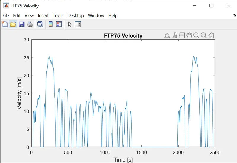
Here the the vehiclereference(input velocity port) is connected to the drivecycle.
vehiclefeedback(outputs velocity data) is connected to the vehiclebody.
Grade(angle of inclination port) is connected with a zero constant input.
info port is for the bus signals which consists of block calculations
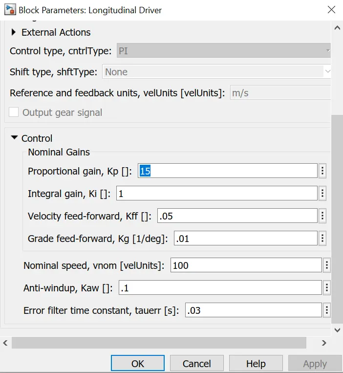
The acceleration and deceleration are connected the control voltage source which is the input of the electricplant.if the reference velocity is greater than feedback velocity an acceleration command will be given as an output to the controlled voltage source.if the reference velocity is less than feedback velocity then deceleration coomand is given as output to the controlled voltage source.
2 ELECTRIC PLANT SUBSYSTEM
Here the subsystem consists of the main electrical connections.
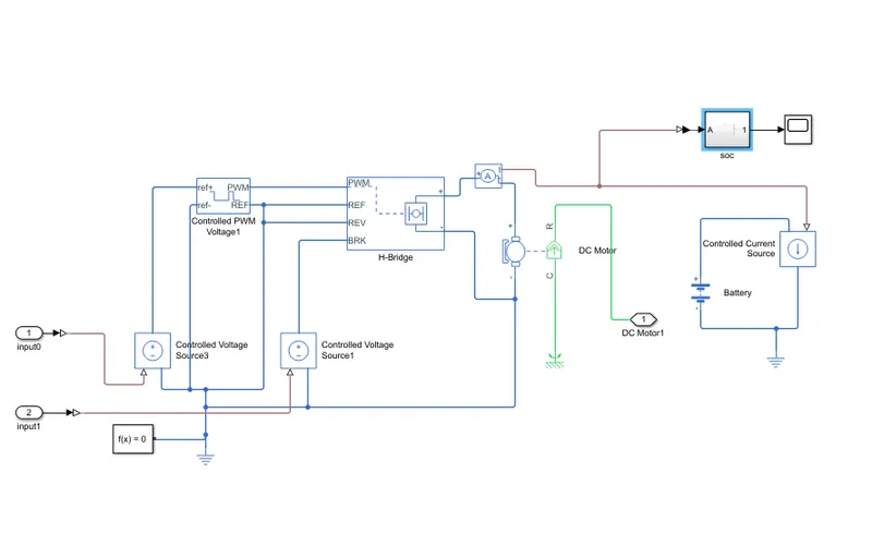
The outputs from the acceleration(1) and decelerayion(2) are connected to a simulink physical signal converter which converts the input velocity data to the input to the physical signals such as voltage to the controlled voltage source.
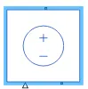
The Controlled Voltage Source block converts a Simulink input signal into an equivalent voltage source. The block represents an ideal voltage source that is powerful enough to maintain the specified voltage at its output regardless of the current passing through it. The output voltage is V = Vs, where Vs is the numerical value presented at the physical signal port.
.The one output from the first controlled voltage source is connected to the reference port of controlled pulsewidth modulation voltage.
CONTROLLED PWM VOLTAGE
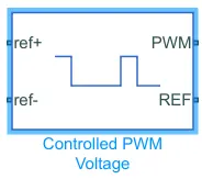
The Controlled PWM Voltage block represents a pulse-width modulated (PWM) voltage source. The block has two modeling variants, accessible by right-clicking the block in your block diagram and then selecting the appropriate option from the context menu
-
Electrical input ports — The block calculates the duty cycle based on the reference voltage across its ref+ and ref- ports. This modeling variant is the default.
-
PS input — Specify the duty cycle value directly by using an input physical signal port.
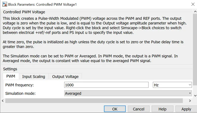
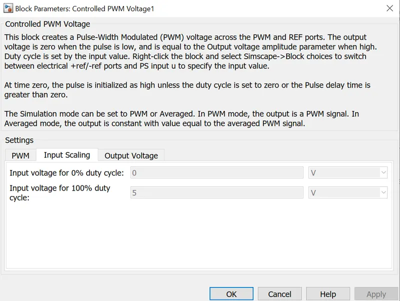
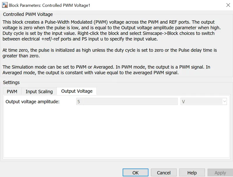
I have used the controlled pwm voltage in rorder to give controlled pulse width modulation to the H bridge.The pwm and reference ports output of the controlled PWM voltage are connected input ports such as PWM and reference of H bridge respectively.if the pulse is low the outputvoltage is considered as V where as if the pulse is high the output voltage will be equal to the output voltage amplitude whic is 240V in the H bridge block the pulses of voltage created by this block are dependent on the duty cycle.The duty cycle is set by the input of the controlled PWM voltage block.
H BRIDGE
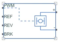
The H-Bridge block represents an H-bridge motor driver. The block has the following two Simulation mode options:The H-Bridge block output is a controlled voltage that depends on the input signal at the PWMport. If the input signal has a value greater than the Enable threshold voltage parameter value, the H-Bridge block output is on and has a value equal to the value of the Output voltage amplitude parameter. If it has a value less than the Enable threshold voltage parameter value, the block maintains the load circuit using the freewheeling mode.
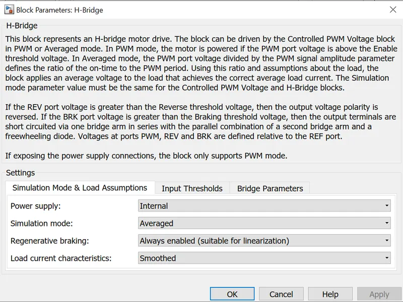
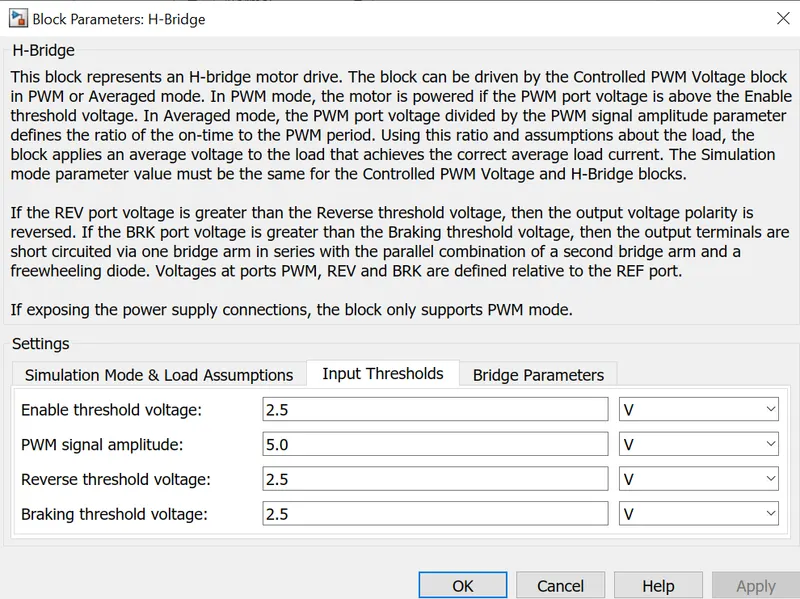
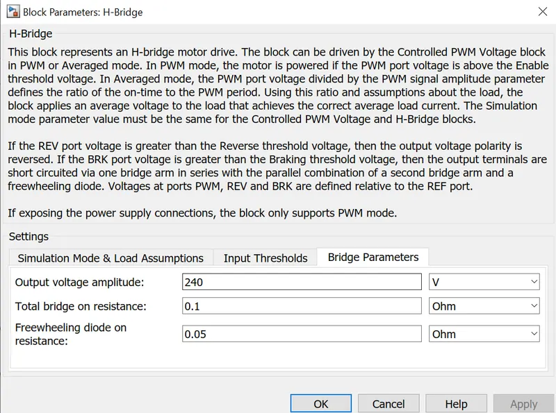
I have chosen H bridge as the power converter which converts the correct form and magnitude of the dc voltage from the battery to the motor.The H bridge has two sides. one is the left side which is controlling of the voltage signal and the other one is the controlled voltage output.
PWM nd REF are connected from the controlled pwm Voltage ports of PWM nd REF respectively.
REV(reverse port) which is connected to the negative reference of the controlle pwm voltage and controlle voltage source.
BRK(brake) which connects the output of the second controlled voltage source
DC MOTOR
Here is the core machine of an electric vehicle which converts the electrical energy to mechanical energy.
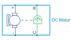
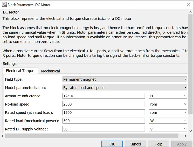
This block represents a dc block with specific torque and speed characteristics .voltage is the input port. it has a mechanical rotational conserving port as output.here we use permanent magnet type dc motor with with 10000 rpm speed at no load,8000 rpm rated speed,75KW rated load.the mechanical side is on the right side and the electrical is on the left side,here C refers to the casing and R refers to the rotation of the motor which produces torque.The elecrical part conmsist of a positive and negative terminals.if the positive of battery is connected to positive of dc motor and negative simulatanously then a positive torque is produced from C to R.The direction of the torque can be changed by changing the sign of back emf to the torque constant.since the cport is stationary it need to connect to a mechanical rotational reference.The R block is connected to a simple gear block in the vehicle body block.The posotive side of the electrical side is connected with the positive terminal of the H bridge.
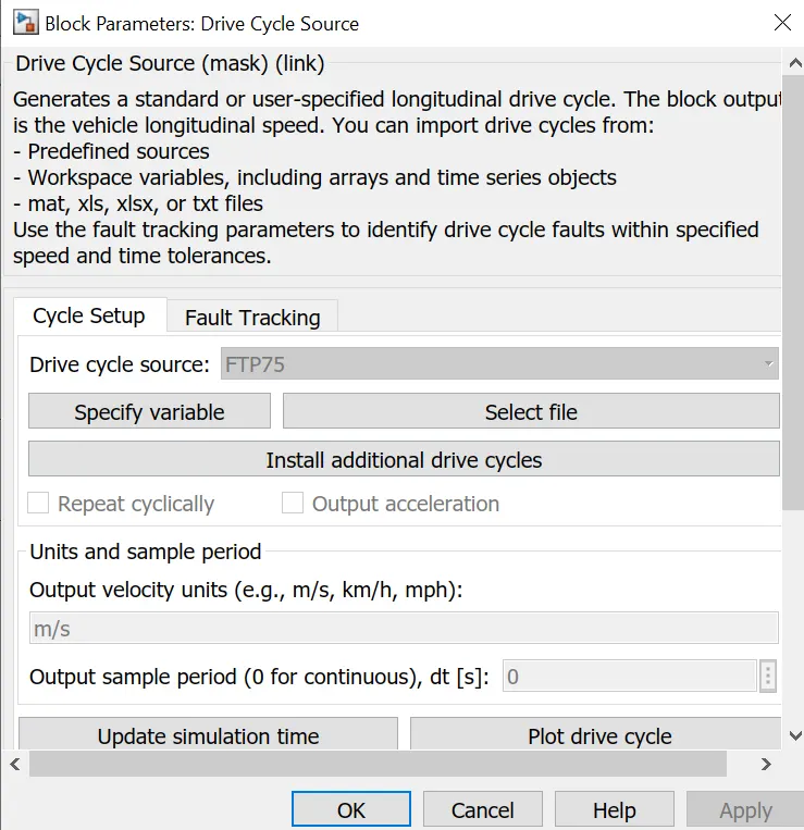
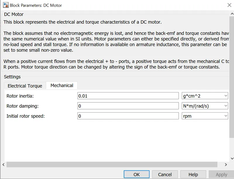
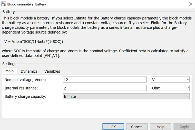
The values of supply voltage,rated voltage and other parametres are changed in the block parameters which are shown below
BATTERY

The battery is connected to the power source of the model taht power is generated and transmitted via a current a controlled current source
CONTROLLED CURRENT SOURCE
The controlled current source controls the amount of the current flows.The output from the controled current source (output of battery) is connected via a current sensor to the dc motor and H bridge.
CURRENT SENSOR
Its used for measuring the amount of current that flows.A SOC is connected with it inorder to check the amount of charge left in the battery.
SOC CALCULATION SUBSYSTEM
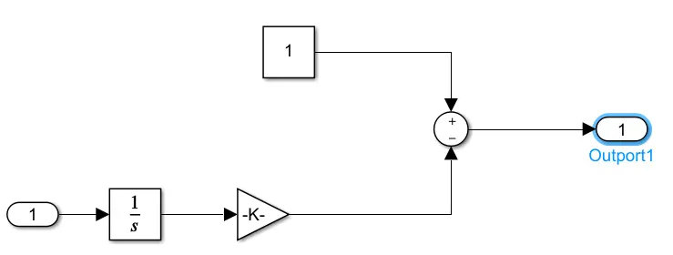
Gain and Integrator are connected in series to the negative port of the sum and a constant to the positive side of operator.The output of the sum is connected to the scope.
Tire
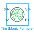 The Tire (Magic Formula) block models the tire as a rigid wheel-tire combination in contact with the road and subject to slip. When torque is applied to the wheel axle, the tire pushes on the ground (while subject to contact friction) and transfers the resulting reaction as a force back on the wheel. This action pushes the wheel forward or backward. If you include the optional tire compliance, the tire also flexibly deforms under load.
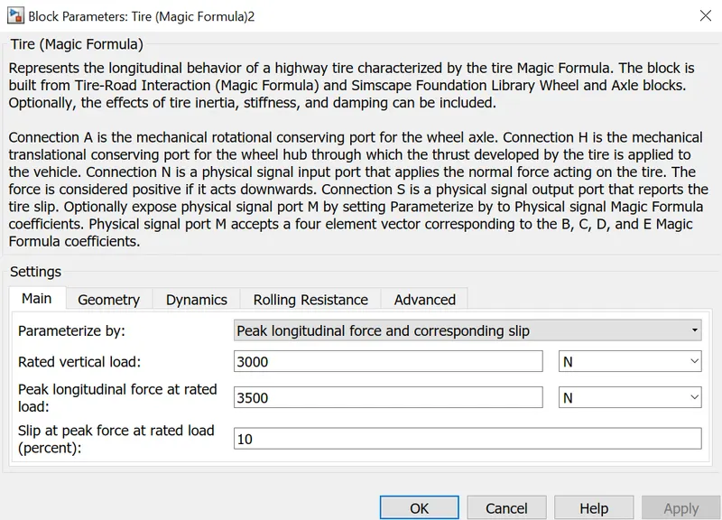
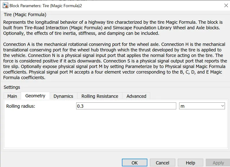
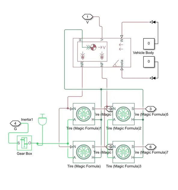
This subsystem is the mechanical part of electric vehicle.its made up of four tires(magic formula).in the groups hub(H) and axle(A) is connected of two tires for rear and front wheel.Hub of the two groups are connected and sends to the hub(H) port of the vehicle body.Rotation(N) of two wheels is connected for rear wheel portion to NR and another two wheels is connected for frontal wheel portion to NF of vehicle body respectively.As the vehicle is rear wheel drive so connected axile of rear wheels is connected to a gearbox and an inertia is added to it.
GEARBOX

The block represents an ideal, non-planetary, fixed gear ratio gear box. The gear box is characterized by its only parameter, Gear ratio, which can be positive or negative. Connections S and O are mechanical rotational conserving ports associated with the box input and output shaft, respectively. The gear ratio is determined as the ratio of the input shaft angular velocity to that of the output shaft.The block generates torque in positive direction if a positive torque is applied to the input shaft and the ratio is assigned a positive value.
Inertia
 represents the mechanical rotational inertia here .01kgm^2 as inertia.
An inertia block has been added to provide ideal mechanical rotational inertian for gear box.the mechanical rotaional conserving port is directly connected to the gearbox.
Vehicle Body
The Vehicle Body block represents a two-axle vehicle body in longitudinal motion. The vehicle can have the same or a different number of wheels on each axle. For example, two wheels on the front axle and one wheel on the rear axle. The vehicle wheels are assumed identical in size. The vehicle can also have a center of gravity (CG) that is at or below the plane of travel.
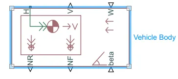
The six ports in the vehicle body are
H this is the hub and is connected to tires to the main body of the vehicle.
V This is a signal output port to measure the velocity of the vehucle which is connected to vehicle feedback of the longitudianl driver through a ps converter and to a scope to measure the velocity.
W This is a physical signal input port which is connected to a constant via ps converter.
NR This is a physical signal output port which is connected to model the rear wheel normal force.
NF This is a physical signal output port which is connected to model the front wheel normal force.
beta This is a physical signal input port which allows to create inclination angle which helps to climbing force.here zero is connected as we are not considering hill climbing.
The block parameters are changed accordingly
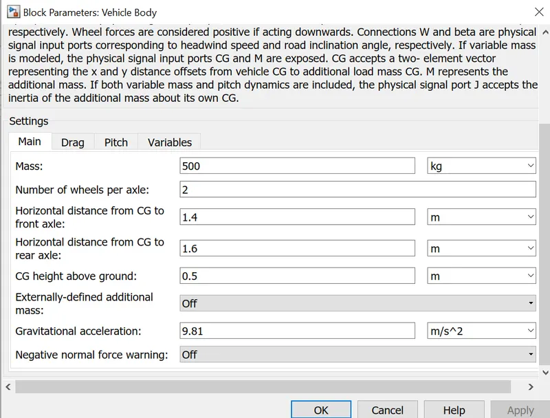
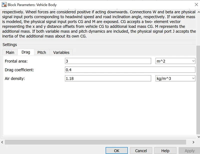
OUTPUT
Battery output graph
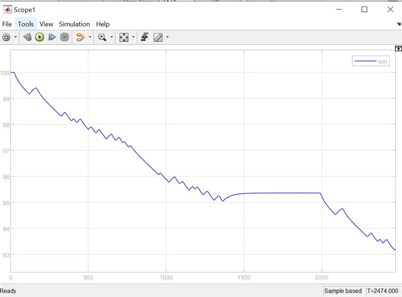
It is clearly visible from the graph that at initial point the battery charge was at 100 % and then it decreases to 90 % at 2472 seconds.As further increase in simulation time decreases the battery charge. so the capacity of the battery can br set as per the requirement.
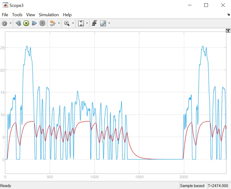
The blue line represents the input and the red line dispalya the output speed of the electric vehicle.It can be concluded that the output is trying to reach as accurate value of input but as we have given varied parametres in dc motor and H bridge the output is trying to achive as per the input.By changing the rated load and dc supply the output can be achieved as input.
CONCLUSION
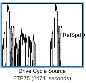
The EV has obtained an output according to the FTP75 Drivecycle and it can be tested that for many drive cycle bay changing the input drive cycle.Vehicle has travelled 6km by the 12 v nominal voltage.In real time the battery capacity can be increased and can travel more distance.The real time outputs may vary from the design as considering the wind, rain and other factors in reality.
The file of the final project of Design of an Electric Vehicle is uploaded