Final Project: Design of an Electric Vehicle
1. System level configurations
Description:Model of Electric Vehicle
Modelling involves a representation of actual system. Before going for actual modelling we will discuss approach to make optimize model.
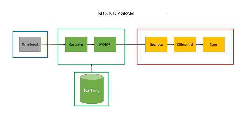
We have divided whole model into 4 parts. The first part is vehcile body which has Tyres, Differential and gearbox. 2nd part has Motor and controller part we have used simple DC motor and H-bridge controller.3rd part is Drive input. In this we will create signal builder block. 4th is Battery from this block diagram Motor will take power from battery. If we directly connect battery to motor then speed control is not possible therefore we will connect controller between battery and Motor.
2. Model parameters
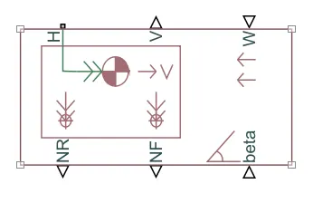
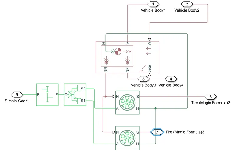
First we will add vehicle body which is chassis of vehicle. In vehicle body we are having 6 ports. H -mean Hub, V - Actual speed of vehicle, W- wind velocity, delta - Inclination of road, NF - Normal force for front wheel and NR- Normal force for rear wheel.
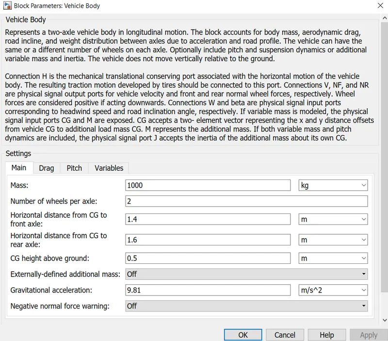
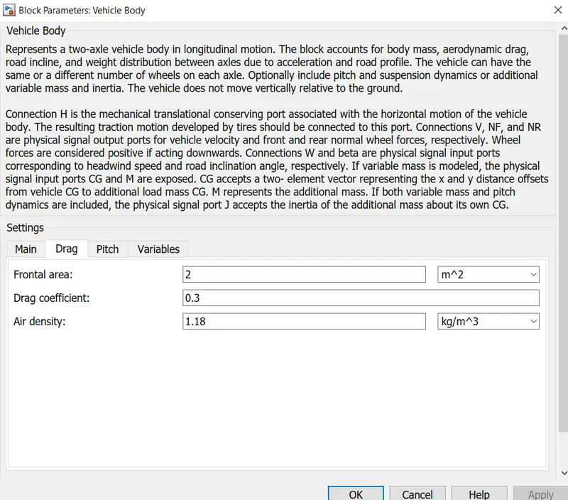
Vehicle Body Parameters
Now add tyres from simscape library. We have considered only 2 tyres.
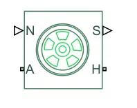
Now connect NR to N of wheels & H to H of wheels.
Now add Differential from simscape library. with the help of differential we can include intia and losses from gear machine.
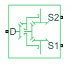
Now add simple gear F termial of Gear we will connect to D terminal of differential.Also connect S1 & S2 of differential to the wheel Axels. To get positive velocity change parameter from gear block.
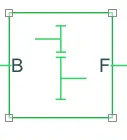
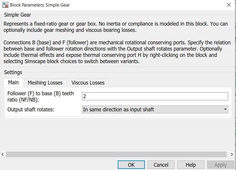
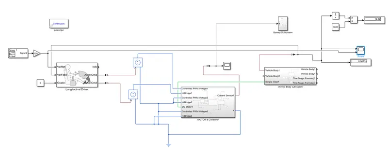
This all connection will create the vechile body subsystem. From this subsystem we are going to examine actual speed of the vehicle. Now we will connect scope and display to port V of vehicle Body.Now we can measure actual speed of the vehicle. We will add PS - Simulink converter to connect Scope and display. This will make our 1st Subsystem.
Now create Motor and controller part
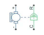
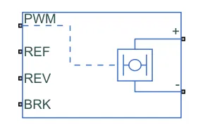
MOTOR Controller
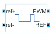
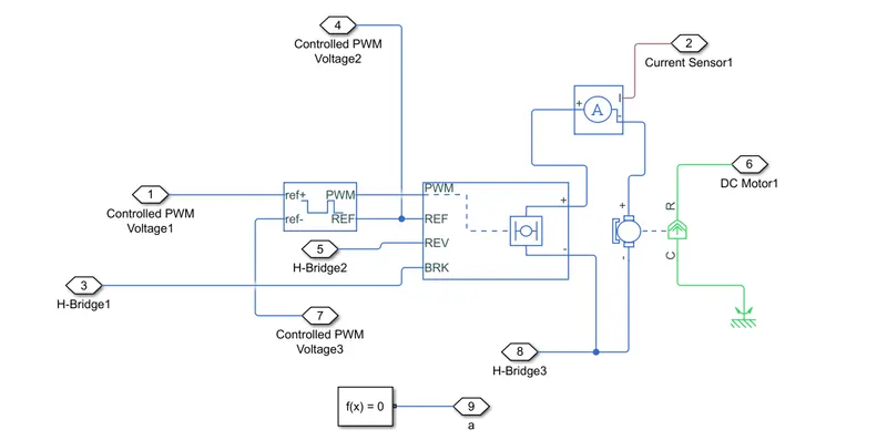
Add DC motor from simscape library. To control DC motor add H bridge converter and to measure current to the motor add current sensor and now connect the terminals, connect R terminal of motor to gear box and C would be connected to mechanical rotational reference. To control PWM input add control PWM voltage.
Now with the help of H bridge we can perform acceleration,braking and reverse mechanism. H bridge require powersupply to operate.In H bridge Powersully we can manage externally as well as internally.Now change the parameters of H bridge.Change simulation mode to average it will reduce simulation time. Change Input thresholds. Change the values as required to get the optimized model.Under bridge parameter make output voltage amplitude 50V.
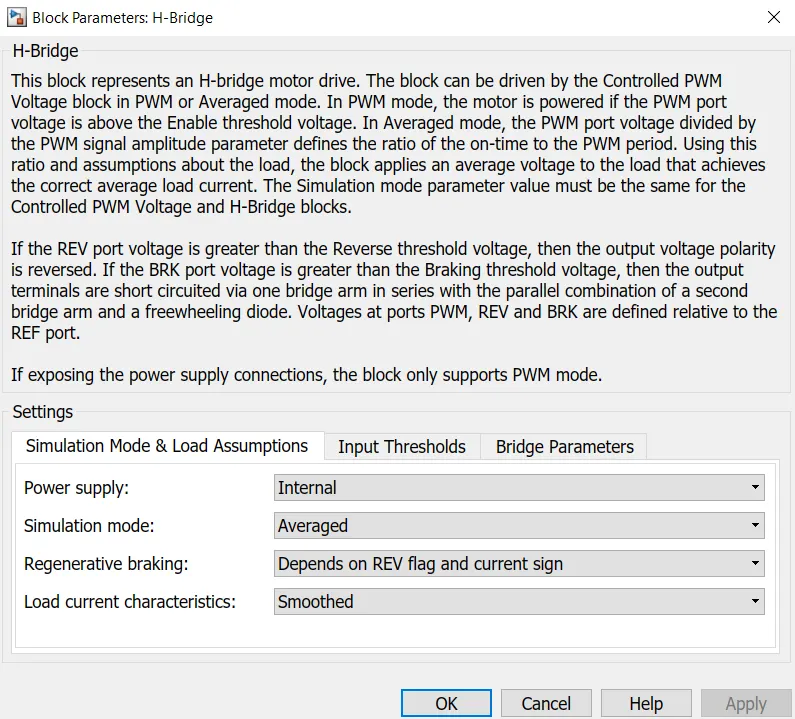
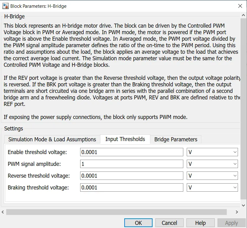
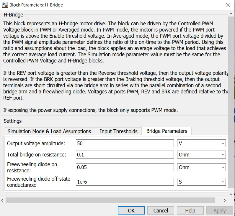
Now change the parameter from control PWM voltage block.First change simulation mode to average now change input scaling, make lower value 0 and higher value to 1.Also make out voltage amplitude to 1
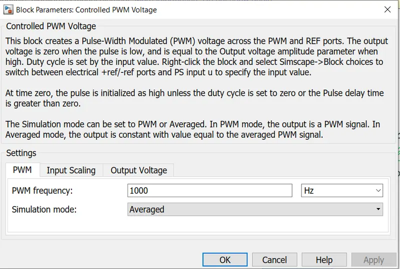
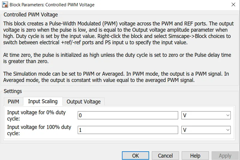
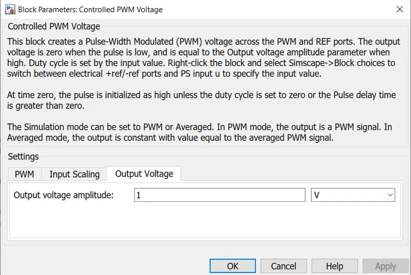
This Block will get Input from Driver and driver would be providing iput interms of 0 or 1 so we have choosen 0 and 1 as low value and high value respectively. add scope to observe current to motor. To connect physical signal and digital signal we need PS to simulink block.
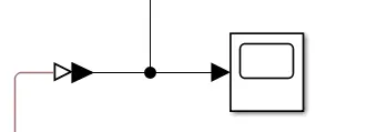
Now connect all negative reference and reverse ports to electrical reference that is ground and connect solver configuration to the ground.This all connection will make our 2nd subsystem.
Now make 3rd subsystem that is Driver Input.Add longitudinal driver from powertrain block set. Change parameter ref. feed back to km/hr.Let us discuss the port of longitudinal driver.
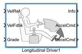
We are going to provide reference signal by adding inbuilt drive cycle or by creation our own signal with the help of signal builder block we are going to connect actual speed of vehicle to the port velocity feed back grade port would be connected to constant value here contanst value assumed to be 0. we will get acceleration command from AccelCmd port and deleration command from DecelCmd port. we can't directly connect this digital signal to physical signal we need simulink to PS converter. Now add simulink to PS converter. In between acceleration command and reference positive port we will add control voltage source from simscape library.
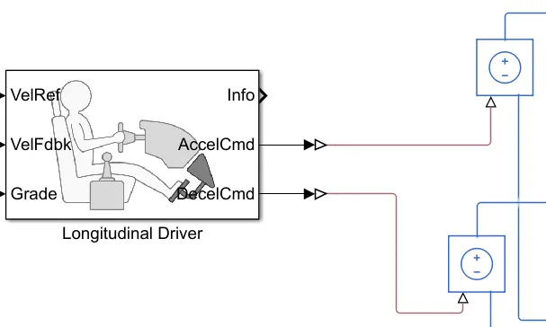
This block is having ability to provide same voltage throughout the circuit. Now connect the ports. Also, connect deleration command to braking force. Now we will create our own signals for 1000 seconds by using signal builder block.
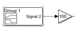
Add signal builder block and add gain block to decide maximum value and make gain value as 100. so our maximum speed can be 100km/hr now create signal by clicking on signal builder block.we are going to run simulation model for 1000sec so go to axes tool and change maximum time to 1000sec. and create a new signal. 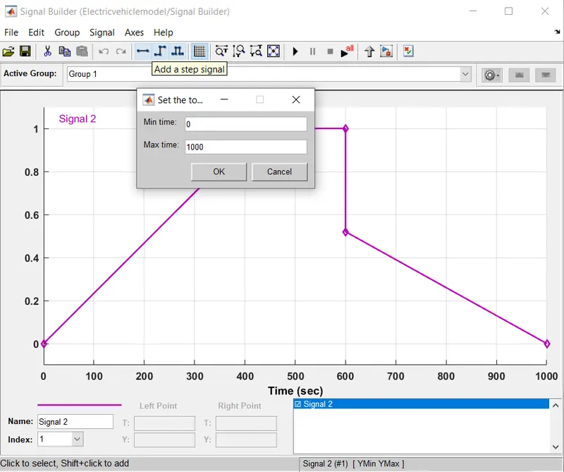
Now connect actual speed to the feed back velocity.Add one port to scope for checking reference speed and this all connection will create our 3rd subsystem.
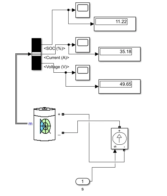
Now we can create our last and important sub system that is Battery Pack to check SOC percentage. For this we need battery and check the parameters.

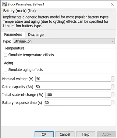
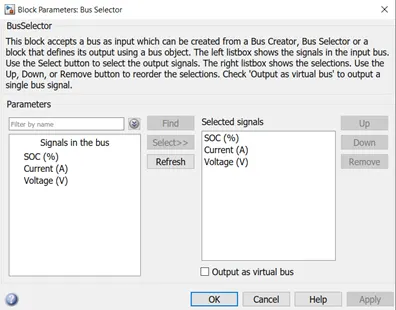
we will choose lithium -Ion battery and above parameters states that the battery is 100% charged. Change nominal voltage and rated capacity to 50. Now add bus secetor. double click on bus sector to check the parameters. Add all signals SOC,Current and voltage.


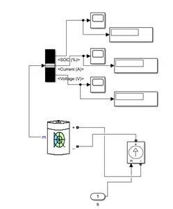
Now connect scope and display to each port. Add controlled current source from power system fundamental blocks. It will also work like controlled voltage source and make the connections. This is the same current which will flow from battery to motor during acceleration and during braking action current will flow from motor to battery. This is our 4th and last subsystem we can run the simulation.
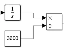
Now we can will run the simulation for 1000seconds. we will get reference velocity and actual speed of vehicle. We can also observed average velocity of the vehicle to calculate manually we can use basic formula i.e speed = distance/time. To calculate distance we have to take integration of velocity and we have to divide the value by 3600sec. now add the block make the connections.
we haven't changed the motor parameter earlier. By changing motor parameters, we can examine how actual speed is trying to match reference speed.
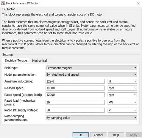
One thing we have to understand that if the rated speed is less then we will get more difference between reference speed and actual speed. so if we getting more difference between reference speed and actual speed then we can reduce this difference by increasing the rated speed or decreasing the vehicle body weight. Add power Gui block. Now run the simulation and examine the graph.
Results & Conclusion
SOC % (State of charge)
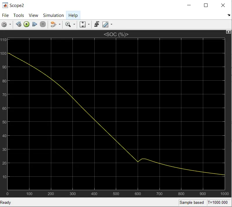
Here battery is discharged non linearly for 400sec. and for next 200sec battery discharge linearly and remaing battery has charged and discharged according to feedback. If we check the actual and reference graph, we conclude following things. 1) actual speed is trying to follow reference speed
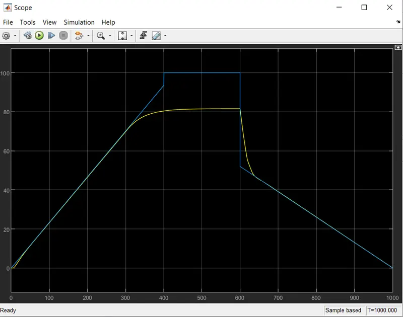
Distance is approximately 12.5km time is 1000sec first convert time to hours and after that divide distance by time we will get an average speed.