Final Project: Design of an Electric Vehicle
Create a MATLAB model of electric car which uses a battery and a DC motor. Choose suitable blocks from Powertrain block set. Prepare a report about your model including following:
Solution: Objectives:
1. System level configurations
System level configuarations of EV includes Different architecture like
- Battery electric vehicles are powered by electricity stored in a battery pack.
- Plug-in hybrids combine a gasoline or diesel engine with an electric motor and large rechargeable battery.
- Fuel cell vehicles split electrons from hydrogen molecules to produce electricity to run the motor.
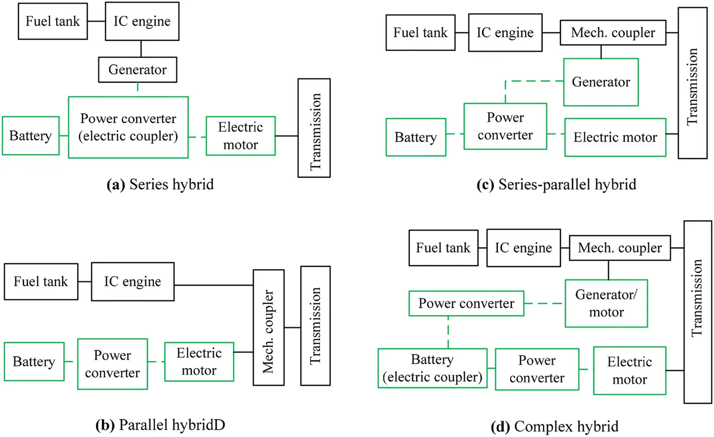
In Hybrid electric vehicle we have
a) Series hybrid electric vehicle.
b) Parallel hybrid electric vehicle
c) Series-parallel hybrid electric vehicles.
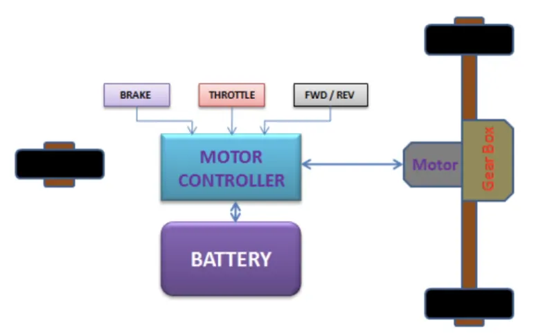
Battery Electric vehicle power train blockset.
HEV Powertrain model.
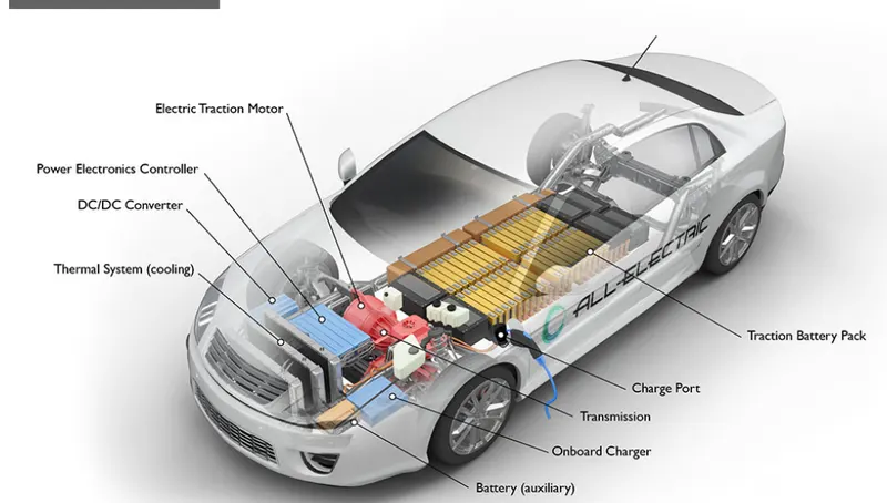
The physical elements of Electric vehicles are.
A) Traction Battery pack: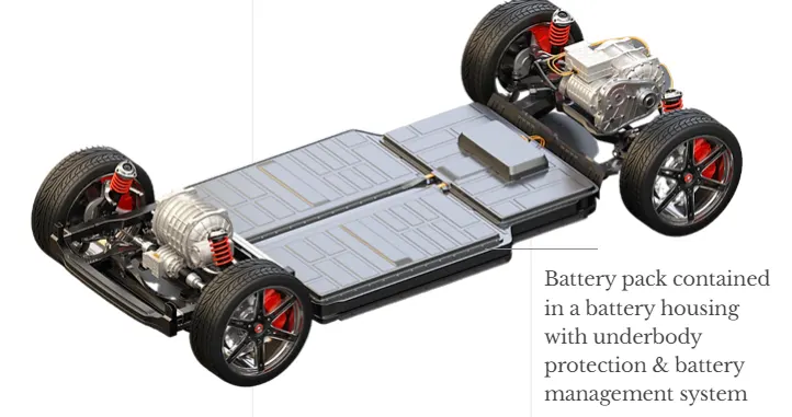
An EV traction battery is rechargeable energy storage that supplies power to the electric motor very quickly, giving EVs high performance & rapid acceleration.
Multiple individual lithium ion battery cells are connected to make a battery module. A group of connected battery modules is contained within an enclosed battery casing with underbody protection. This is known as a battery pack.
B) Power converters and controllers:A power converter is an electrical circuit that changes the electric energy from one form into the desired form optimized for the specific load.
Few power converters are listed below:
- AC to DC Converter (Controlled Rectifier)
- DC to DC Converter (DC Chopper)
- AC to AC Converter (AC voltage regulator)
- DC to AC Converter (Inverter)
The electric vehicle controller is the electronics package that operates between the batteries and the motor to control the electric vehicle's speed and acceleration much like a carburetor does in a gasoline-powered vehicle.
c) Traction inverter:
3) Simple gear
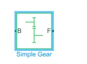
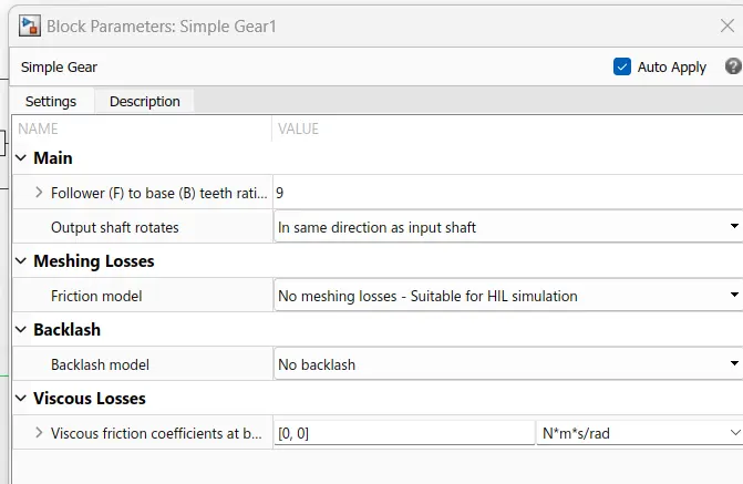
Connections B (base) and F (follower) are mechanical rotational conserving ports. Specify the relation between base and follower rotation directions with the Output shaft rotates parameter.
Follower (F) : port is connected to Motor , B base is connected to Front or rear axle.
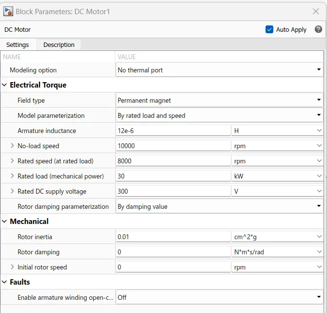
4) DC Motor:
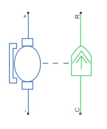
This block represents the electrical and torque characteristics of a DC motor.
The block assumes that no electromagnetic energy is lost, and hence the back-emf and torque constants have the same numerical value when in SI units. Motor parameters can either be specified directly, or derived from no-load speed and stall torque. If no information is available on armature inductance, this parameter can be set to some small non-zero value.
When a positive current flows from the electrical + to - ports, a positive torque acts from the mechanical C to R ports. Motor torque direction can be changed by altering the sign of the back-emf or torque constants.
5) H-bridge
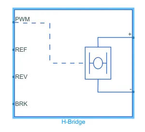
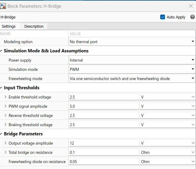
This block represents an H-bridge motor drive. The block can be driven by the Controlled PWM Voltage block in PWM or Averaged mode. In PWM mode, the motor is powered if the PWM port voltage is above the Enable threshold voltage. In Averaged mode, the PWM port voltage divided by the PWM signal amplitude parameter defines the ratio of the on-time to the PWM period. Using this ratio and assumptions about the load, the block applies an average voltage to the load that achieves the correct average load current.
If the REV port voltage is greater than the Reverse threshold voltage, then the output voltage polarity is reversed. If the BRK port voltage is greater than the Braking threshold voltage, then the output terminals are short circuited via one bridge arm in series with the parallel combination of a second bridge arm and a freewheeling diode. Voltages at ports PWM, REV and BRK are defined relative to the REF port.
6)Controlled PWM voltage
The parameteres set are
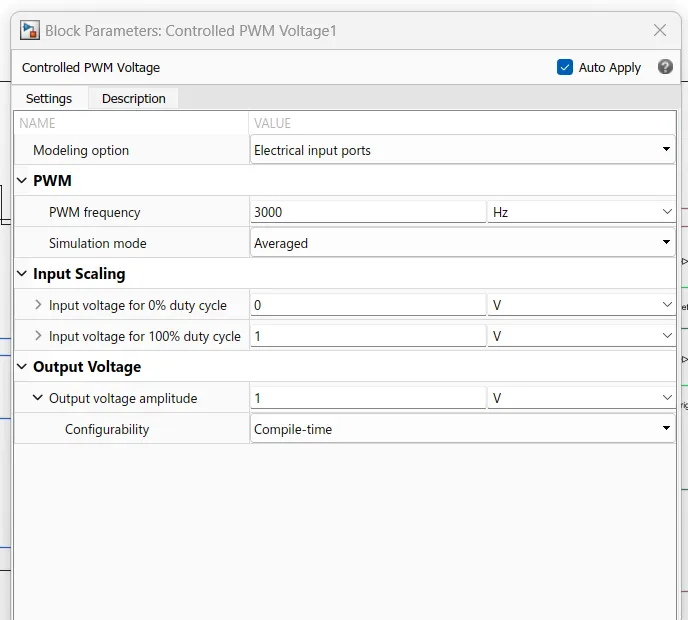
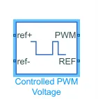
This block creates a Pulse-Width Modulated (PWM) voltage across the PWM and REF ports. The output voltage is zero when the pulse is low, and is equal to the Output voltage amplitude parameter when high. Duty cycle is set by the input value.
At time zero, the pulse is initialized as high unless the duty cycle is set to zero or the Pulse delay time is greater than zero.
The Simulation mode can be set to PWM or Averaged. In PWM mode, the output is a PWM signal. In Averaged mode, the output is constant with value equal to the averaged PWM signal.
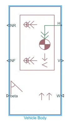
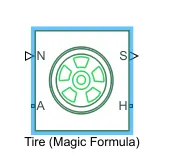
7)Longitudinal Driver block:
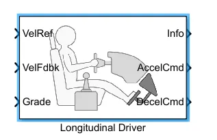
A parametric longitudinal speed tracking controller for generating normalized acceleration and braking commands based on reference and feedback velocities.
8)
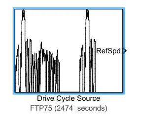
Generates a standard or user-specified longitudinal drive cycle. The block output is the vehicle longitudinal speed. You can import drive cycles from:
- Predefined sources
- Workspace variables, including arrays and time series objects
- mat, xls, xlsx, or txt files
Use the fault tracking parameters to identify drive cycle faults within specified speed and time tolerances.
Below is the model designed for EV power train.
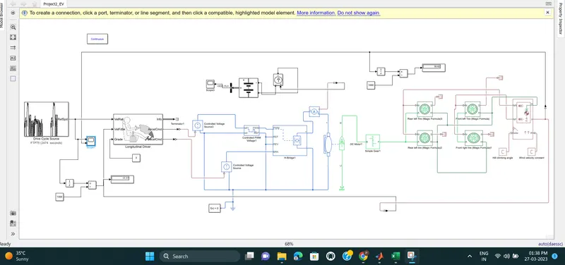
The block diagram of EV powertrain model is shown below. 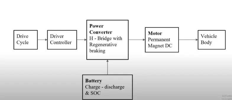
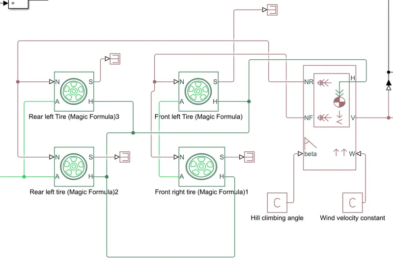
The ouput obtained after running the model for 2474 sec is shown below.
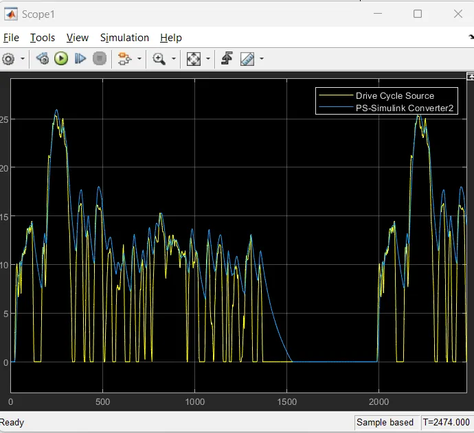
And the reference drive cycle FTP75 output is 17.7Km whereas obtained output is 24km.
So to match the output wrt input we have to fine tune the parametres related to speed, voltage and current controllers.
The gear ratio of Simple gear block value is increased and total bridge on resistance of H bridge block is reduced and Input Voltage for 100% duty cycle and output voltage for 100% duty cycle of PWM signal is reduced to get desired output as shown below.
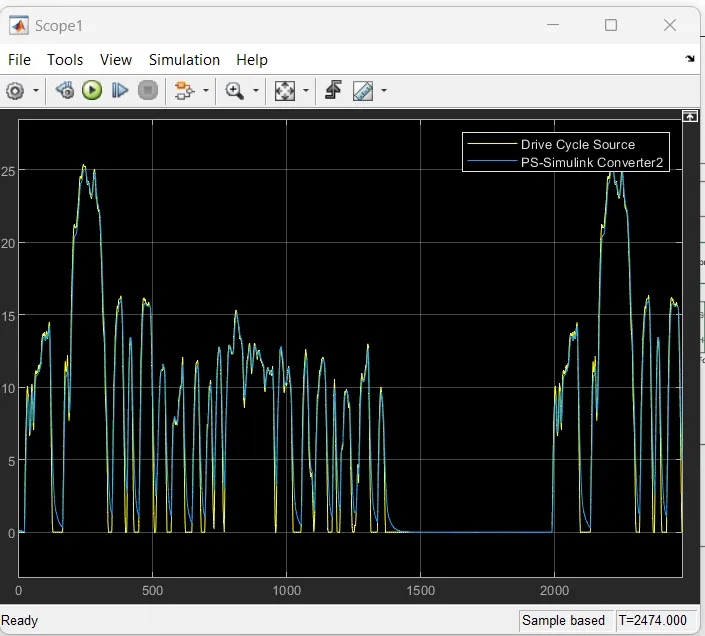
In above case output obtained is aprox 19 Km matching near to reference FTP75 2474sec drive cycle.
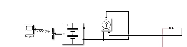
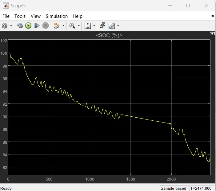
* A generic battery is used here to check the SOC of battery , when vehicle moves for 2474 seconds.