Final Project: Design of an Electric Vehicle
Aim:
Create a MATLAB model of electric car which uses a battery and a DC motor. Choose suitable blocks from Powertrain block set. Prepare a report about your model including following:
Objective:
1. System level configurations
2. Model parameters
3. Results
4. Conclusion
Solution:
An Electric vehicle is modern trend in now a day. An Engine vehicles are produce pollution which result in global warming.An Electric vehicle is define as a vehicle that can be powered by the electrical motor with an approprate electric controller, converter and battery system. And battery can be charge by the both onboard or offboard charge with an help of external source.
Main component in Electric Vehicle:
- Electric Motor
- Power Controller
- Power Converter
- Battery
- Transmission.
Electric Motor:
Electric motor used for an Electric vehicle are two type one is AC Motor another one is DC Motor. In particularly an AC motor preferable for Electric Vehicle is Induction Motor, Where an DC motor preferable for electric vehicle is Bladeless DC Motor.
Induction Motor:
Induction motor is also known as AC machine, It consist of Rotor and Stator, The Rotor and stator are made up of copper winding with an particular arrangement like overlap winding for Stator and Field Winding for Rotor, It can be operated at 3phase AC sypply with an phase diffrence if 120 degree.
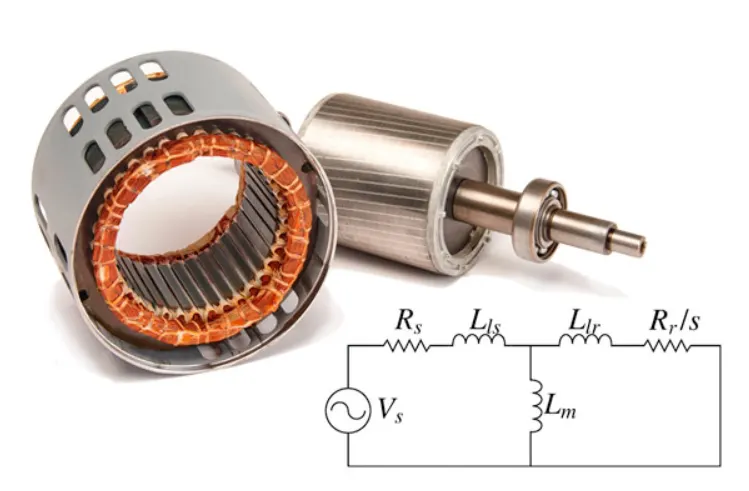
The name induction motor define that the supply given to the stator induced the magnetic field in the rotor to rotate the motor. Due to the rotor field and stator field the torque is produce in the motor. The torque induced on the motor is called as electromagnetic torque.
If the torque and magnetic field of the motor are allign in the same direction then the motor start rotating in the direction of magnetic field.
simulink model:
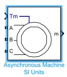
In an above simulink model 'A','B' and 'C' indicate the 3 phase connection of the machine, where 'Tm' is the reference torque required to control the motor according to the torque requirement and 'm' is the measurement point used to measure machine parameter.
BLDC Motor:
BLDC motor is contain stator and rotor,where rotor contains permanent magnet and stator contains copper winding and the Hall effect sensor are placed in between two stator to sense the magnetic effect , And winding is connected to an power controller to control the magnetic field of the stator coil with the flow of current direction, The special function of the motor shows there is no brushes are buit inside the motor so there is no spark loss.
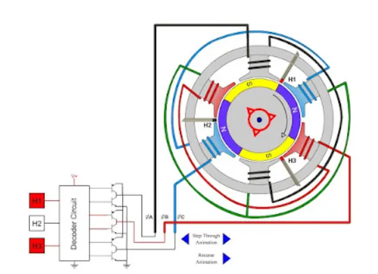
Where all the coils are not energiezed at same time, there are 3 coils are energized in controlled manner,In these model 2 coils are energized at same time with an opposite polarity so only the permanent magnet try to caught the opposite field and the field transfer from one coil to another.
The input to the coils can be controlled by implement the switch and Turn ON and OFF the switch at particular time interval to produce an magnetic field in the coil to control the speed of motor.
When the stator coils are electrically switched by a supply source, it becomes electromagnet and starts producing the uniform field in the air gap. Though the source of supply is DC, switching makes to generate an AC voltage waveform with trapezoidal shape. Due to the force of interaction between electromagnet stator and permanent magnet rotor, the rotor continues to rotate.
Simulink model:
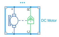
In an above simulink model '+' and '-' are the positive and negative connection of the DC Motor where 'C' and 'R' are the mechanical Rotational component and the direction of the mechanical Rotational Component is 'C' to 'R'.
Power Controller:
Power Controller is an semi-conductor devices that is used to control the electrical circuit. There are three common pin in the device namely Gate, Emitter and collector where gate is used to controlled the power input and output. There are various type of power controller device available now a day. Namely BJT, MOSFET, IGBT and SCR.
BJT:
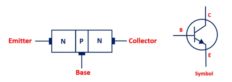
A bipolar junction transistor is a three-terminal semiconductor device that consists of two p-n junctions which are able to amplify or magnify a signal.
It is a current controlled device. The three terminals of the BJT are the base, the collector, and the emitter. A signal of a small amplitude applied to the base is available in the amplified form at the collector of the transistor.
This is the amplification provided by the BJT. Note that it does require an external source of DC power supply to carry out the amplification process.
Simulink Model:
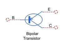
In an above simulink model 'B' represent the Base, 'E' represent the Emitter and 'C' represent the collector of the transistor. Base is the controller of the device.
MOSFET:
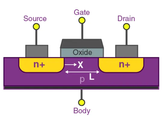
Metal Oxide Silicon Field Effect Transistors commonly known as MOSFETs are electronic devices used to switch or amplify voltages in circuits. It is a voltage controlled device and is constructed by three terminals. While compare to all power controller MOSFET reaction speed is faster. In an power controller The terminals of MOSFET are named as follows:
- Source
- Gate
- Drain
- Body
Simulink Model:
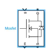
In an above simulink model 'g' represent the Gate input, 'S' represent the Source, 'D' represent the Drain and 'M' represent the Measurement of device paraameter. When an input power is zero then the gate signal is automatically turn off.
IGBT :
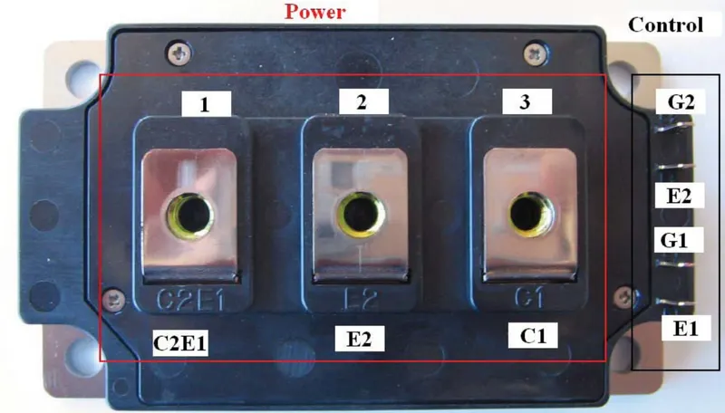
IGBT is a relatively new device in power electronics and before the advent of IGBT, Power MOSFET and Power BJT were common in use in power electronic applications.
Both of these devices possessed some advantages and simultaneously some disadvantages. On one hand, we had bad switching performance, low input impedance, secondary breakdown and current controlled
IGBT is used in the place where heavy load current need to carry by the device but the response time is high when compare to MOSFET.
Simulink Model:
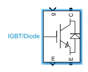
In an above simulink model 'g' represent the Gate input, 'S' represent the Source, 'D' represent the Drain and 'M' represent the Measurement of device paraameter. Where gate is the controller of the device.
SCR:
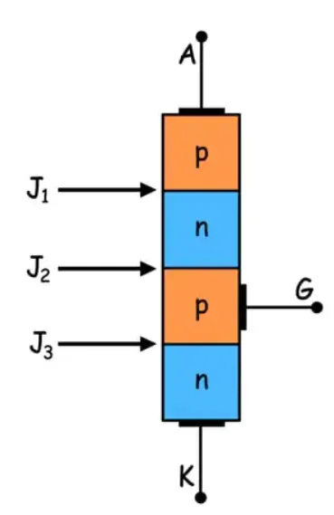
Silicon Controlled Rectifier (SCR) is a unidirectional semiconductor device made of silicon. This device is the solid state equivalent of thyratron and hence it is also referred to as thyristor or thyroid transistor.
In fact, SCR (Silicon Controlled Rectifier) is a trade name given to the thyristor by General Electric Company. Basically, SCR is a three-terminal, four-layer semiconductor device consisting of alternate layers of p-type and n-type material.
Simulink Model:
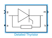
In an above simulink model 'g' represent the Gate input, 'S' represent the Source, 'D' represent the Drain and 'M' represent the Measurement of device paraameter. Where gate is the controller of the device.
Power Converter:
Power Converter is device which is used to convert an one source to another source with an controlled output. There are various type of Power Controller device available now a day. They are 4 types of power converter are available.
- Inverter(DC-AC)
- Rectifier(AC-DC)
- Chopper(DC-DC)
- Regulator(AC-AC)
Inverter(DC-AC):
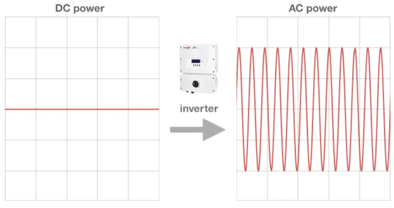
An inverter converts the DC voltage to an AC voltage. In most cases, the input DC voltage is usually lower while the output AC is equal to the grid supply voltage of either 120 volts, or 240 Volts depending on the country.
The inverter may be built as standalone equipment for applications such as solar power, or to work as a backup power supply from batteries which are charged separately.
The other configuration is when it is a part of a bigger circuit such as a power supply unit, or a UPS. In this case, the inverter input DC is from the rectified mains AC in the PSU, while from either the rectified AC in the in the UPS when there is power, and from the batteries whenever there is a power failure.
There are different types of inverters based on the shape of the switching waveform. These have varying circuit configurations, efficiencies, advantages and disadvantages
Rectifier(AC-DC):
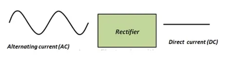
In electronics, Rectifier circuit is the most used circuit because almost every electronic appliance operates on DC (Direct Current) but the availability of the DC Sources are limited such as electrical outlets in our homes provide AC (Alternating current).
The rectifier is the perfect candidate for this job in industries & Home to convert AC into DC. Even our cell phone chargers use rectifiers to convert the AC from our home outlets to DC. Different types of Rectifiers are used for specific applications.
Many electronic circuits require rectified DC power supply for powering various electronic basic components from available AC mains supply. The simple bridge rectifier is used in a variety of electronic AC based power devices.
Chopper(DC-DC):
DC to DC converter is very much needed nowadays as many industrial applications are dependent upon DC voltage source. The performance of these applications will be improved if we use a variable DC supply. It will help to improve controllability of the equipments also.
Examples of such applications are subway cars, trolley buses, battery operated vehicles etc. We can control and vary a constant DC voltage with the help of a chopper.
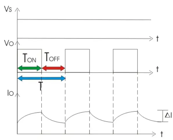
Chopper is a basically static power electronics device which converts fixed DC voltage/power to variable DC voltage or power. It is nothing but a high speed switch which connects and disconnects the load from source at a high rate to get variable or chopped voltage at the output.
Regulator(AC-AC):
voltage regulator, any electrical or electronic device that maintains the voltage of a power source within acceptable limits. The voltage regulator is needed to keep voltages within the prescribed range that can be tolerated by the electrical equipment using that voltage.
Such a device is widely used in motor vehicles of all types to match the output voltage of the generator to the electrical load and to the charging requirements of the battery. Voltage regulators also are used in electronic equipment in which excessive variations in voltage would be determental.
In motor vehicles, voltage regulators rapidly switch from one to another of three circuit states by means of a spring-loaded, double-pole switch. At low speeds, some current from the generator is used to boost the generator’s magnetic field, thereby increasing voltage output.
At higher speeds, resistance is inserted into the generator-field circuit so that its voltage and current are moderated. At still higher speeds, the circuit is switched off, lowering the magnetic field. The regulator switching rate is usually 50 to 200 times per second.
Battery:
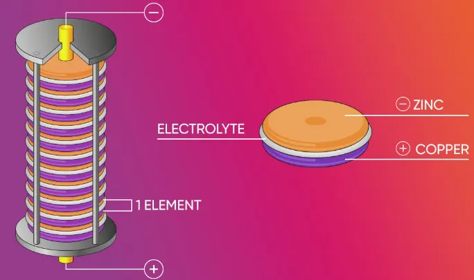
A battery can be defined as an electrochemical device (consisting of one or more electrochemical cells) which can be charged with an electric current and discharged whenever required. Batteries are usually devices that are made up of multiple electro chemical cells that are connected to external inputs and outputs.
Batteries are widely employed in order to power small electric devices such as mobile phones, remotes, and flashlights. Historically, the ‘term’ battery has always been used in order to refer to the combination of two or more electrochemical cells. However, the modern definition of the term ‘battery’ is believed to accommodate devices that only feature a single cell.
Batteries are broadly classified into two categories, namely primary batteries and secondary batteries. Primary batteries can only be charged once. When these batteries are completely discharged, they become useless and must be discarded.
The most common reason why primary batteries cannot be recharged is that the electrochemical reaction that takes place inside of them is irreversible in nature. It is important to note that primary batteries are also referred to as use-and-throw batteries.
Lithium-ion battery:
Lithium-ion batteries are currently used in most portable consumer electronics such as cell phones and laptops because of their high energy per unit mass relative to other electrical energy storage systems.
They also have a high power-to-weight ratio, high energy efficiency, good high-temperature performance, and low self-discharge. Most components of lithium-ion batteries can be recycled, but the cost of material recovery remains a challenge for the industry.
The U.S. Department of Energy is also supporting the Lithium-ion Battery recycling Price to develop and demonstrate profitable solutions for collecting, sorting, storing, and transporting spent and discarded lithium-ion batteries for eventual recycling and materials recovery.
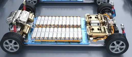
Most of today's all-electric vehicles and PHEVs use lithium-ion batteries, though the exact chemistry often varies from that of consumer electronics batteries. Research and development are ongoing to reduce their relatively high cost, extend their useful life, and address safety concerns in regard to overheating.
Transmission :
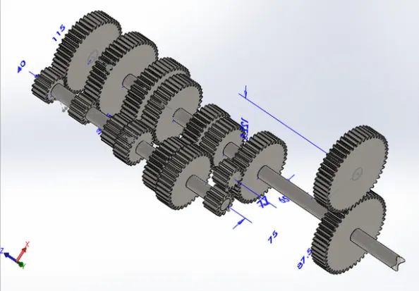
Transmission systems transfer mechanical power from a source to another machine components. For example let us consider a car, in which the power from engine is transmitted to wheels through clutch, gearbox, prop shaft and differential, these components are called transmission elements.
If we consider a lathe, power from motor is provided to a chuck through belt drive and gearbox, these components are transmission elements. A number of elements like gears in a gear box together form a transmission system.
Design of Electric Vehicle using Simulink:
Now a design of the electric vehicle using simulink by the uses of component available in simulink.
Block Diagram:
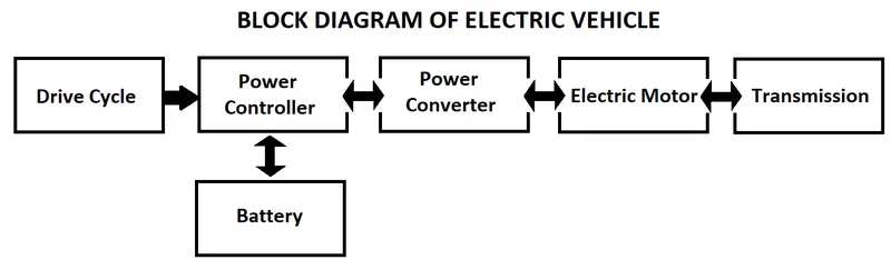
The below given block diagram explain the flow chart of how the electric vehicle work, Let us design the each block and explain step by step.
Design of Drive Cycle:
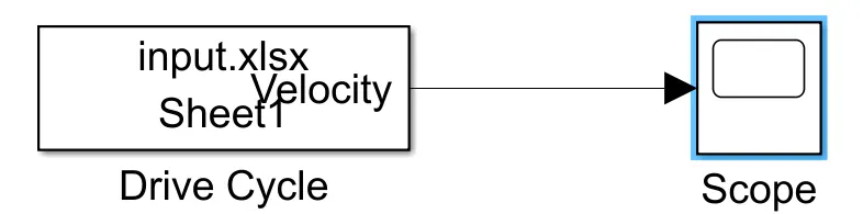
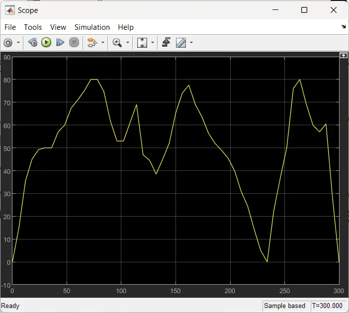
In simulink a 'From Sheet' block is used to design the drive cycle by the help of spreedsheet all value are feed in the excel and using the 'From Sheet' block to take an input from the sheet.
Simulink model:
Graph:
Design of Power Controller:
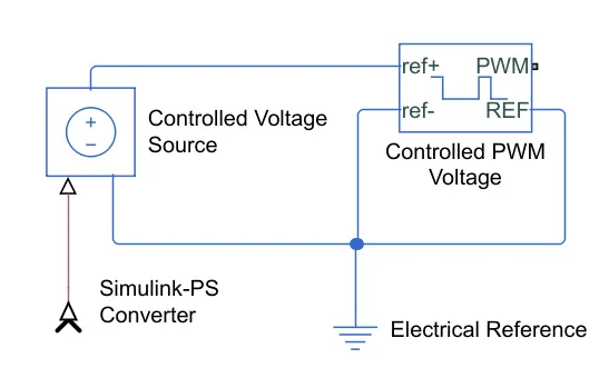
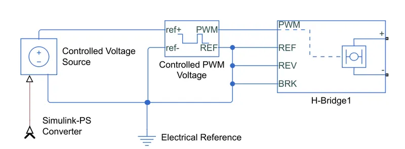
For controlled the input power supply by the controlled the input voltage source, Here 'Controlled voltage Source' block is used to control the input voltage and the PWM is used to control the voltage by the pulse difference. Where an Controller take an input of Physical Signal, So the Simulink-PS Converter is used to convert the Simulink signal to the Physical Signal. Where an implement the ground to the system to protect the system 'Electrical Reference' block is used.
Simulink Model:
Design of the Power Converter:
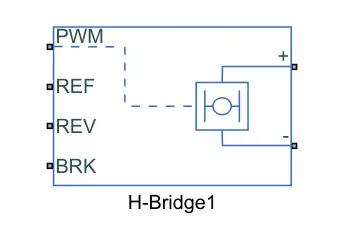
A DC motor can be controlled by various power controller in that the BJT H-Bridge is one of power controller for DC Motor.
A H-Bridge is constructed in the shape of 'H' where the motor is place in the center of two vertical line. These two vertical line are constructed by the uses of power electronics like BJT, MOSFET and IGBT but in these circuit they user BJT power electronics. And these H-Bridge is connected to the DC Voltage.The Circuit given below.
H-Bridge is made for rotate the motor in two direction one is clockwise direction another is anti-clockwise direction. These can be achieved by the controlling of base(B) signal in BJT(Bipolar Junction Transistor).For an motor rotate in an clockwise direction or forward the Q1 and Q4 must be ON and Q2 and Q3 must be OFF.
For an motor rotate in an anti-clockwise direction or backward the Q2 and Q3 must be ON and Q1 and Q4 must be OFF.
Simulink Model:
Simulink Model with an power controller and power converter.
Design of DC motor:
Where all the coils are not energiezed at same time, there are 3 coils are energized in controlled manner,In these model 2 coils are energized at same time with an opposite polarity so only the permanent magnet try to caught the opposite field and the field transfer from one coil to another.
The input to the coils can be controlled by implement the switch and Turn ON and OFF the switch at particular time interval to produce an magnetic field in the coil to control the speed of motor.
When the stator coils are electrically switched by a supply source, it becomes electromagnet and starts producing the uniform field in the air gap.
Though the source of supply is DC, switching makes to generate an AC voltage waveform with trapezoidal shape. Due to the force of interaction between electromagnet stator and permanent magnet rotor, the rotor continues to rotate.
Simulink Model:
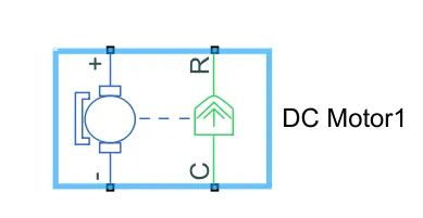
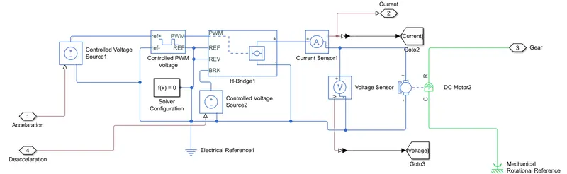
Simulink model of Power Converter, Power Controller and Motor connect.
Design of Transmission:
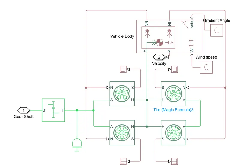
The transmission of the electric vehicle can be depend on the simple gear, vehicle body and tire inertia. And the transmission system is fully depend on the vehicle body to bear the load. In an vehicle the rear and front tire connection are connected to the vehicle body to controlled the vehicle.
And motor shaft is connected to the gear box and the gear control is connected to rear wheel to run the vehicle.
Simulink model:
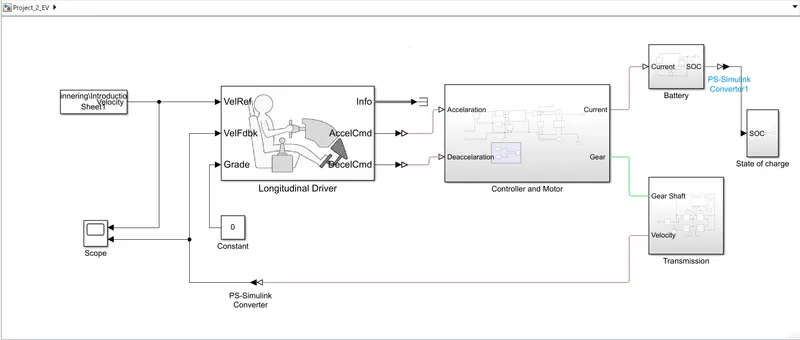
Overall model of electric vehicle:
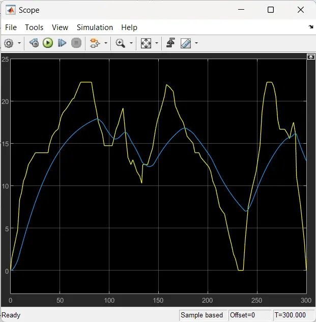
Graph:
Reference and input drive cycle:
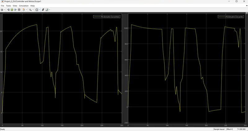
Current and voltage of motor:
State of Charge: