Final Project: Design of an Electric Vehicle
Q: Create a MATLAB model of electric car which uses a battery and a DC motor. Choose suitable blocks from Powertrain block set. Prepare a report about your model including following:
Objectives: System level configurations, Model parameters, Results and Conclusion
An electric vehicle (EV) is a vehicle that uses electric motors for propulsion. It can be powered by a collector system, with electricity from extravehicular sources, or it can be powered autonomously by a battery. The key parameters involved in the design of any electric vehicle are: (i) Range of the vehicle (ii) Speed of the vehicle (iii) Weight carrying capacity of the vehicle. The EVs propulsion system is driven by electric motor rather than a conventional fossil fuel based engines. The electric motor converts electrical energy into mechanical energy is powered by rechargeable batteries which can be charged with the help of charger comprises of AC-DC power converter. In most EVs either permanent magnet synchronous motor or induction motor or switched reluctance motor is used as traction motor to drive the vehicle. The cost of the EV is mainly dependent on type of battery used and the number of batteries required to achieve desired range, speed and weight.
Block diagram of electric vehicle using simulink
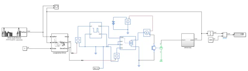
Blocks used in simulink model are: driver cycle source, longitudinal driver, controlled PWM
voltage, controlled voltage source, solver configuration, H-bridge, battery, controlled current source, current sensor, DC motor, mechanical rotational reference, vehicle body, tires, gear box, electrical reference, contant, integrator, scope and display.
Design parameters of electric vehicle: The design of electric vehicle includes the dynamics of the vehicle, capacity and weight of the vehicle, torque and type of motor used, speed required (during up-hill, down-hill and normal road), range of the vehicle, type of battery and DC/DC or DC/AC power converter used.
- Dynamics of the Vehicle: During the design of any EV it is important to know vehicle
dynamics which helps us in understanding its effects on the performance of the vehicle and energy consumption per driven distance. According to Newton’s second law of mechanics, the force (F) due to movement of the vehicle in any given direction can be determined by the sum of all the forces acting on it in the same direction. - Rolling resistance force: Rolling resistance is caused by vehicle tyre during rolling.
- Grading force: Grading force is parallel to road is caused due to road inclination.
- Wheel force: The force on the wheel that has come from traction force of the vehicle to the wheel in order to sustain certain speed level.
- Wheel power and energy: The wheel power ܲcan be determined by the product of tractive force acting on the wheel and speed of the vehicle.
Drive cycle source: A drive cycle refers to a series of specific vehicle operating conditions, such as specific speeds and durations, that a vehicle goes through in order to test its emissions control system. These drive cycles are used by vehicle manufacturers, regulators, and testing facilities to evaluate the performance of a vehicle's emissions control technology and ensure compliance with emissions standards.
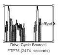
We are using FTP75 drive for this model which is connected to velichle reference in longitudinal driver.
Logitudinal driver: A longitudinal driver refers to a type of driver-assistance system that helps the driver control the speed and acceleration of the vehicle, particularly when traveling on a highway or other long, straight roads. The system uses sensors and other technologies to detect the speed and distance of other vehicles on the road and adjust the speed of the vehicle accordingly, to maintain a safe distance and avoid accidents. It can also help the driver maintain a constant speed, and even accelerate and decelerate automatically in response to traffic conditions.
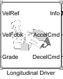
In longitudinal driver we are using the PI control type for the vehicle
Controlled PWM Voltage: Controlled PWM voltage is a method of generating a varying voltage by rapidly switching a DC voltage on and off at a precise frequency, and adjusting the duty cycle (the proportion of time that the voltage is on versus off) to control the average voltage output. This is commonly used in electronic devices to control the speed of motors or the brightness of lights.

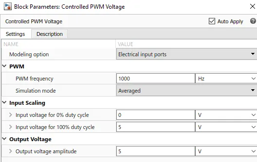
H-bridge: is a type of circuit that allows a voltage to be applied across a load in either direction, It is often used to control the direction of motor and other device that require reversible power, The "H" shape comes from the way that circuit is arranged, with two transistors on one side of the load and two on the other, by creating a bridge like structure.
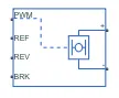
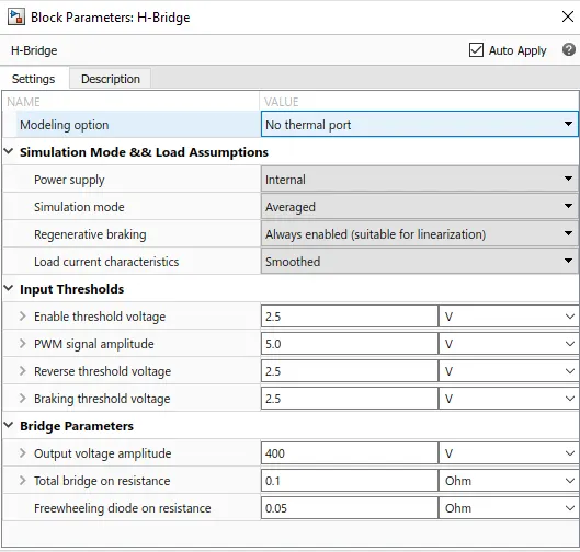
Controlled voltage source: it is required to adjust output voltage in response to changes in a control signal. In our model we are using 2 controlled voltage source one connected to controlled PWM voltage and the other one connected to H- bridge
DC motor: is an electric motor that runs on direct current (DC) power. It uses a simple design that converts electrical energy into mechanical energy through the interaction of a rotor (rotating part) and a stator (stationary part) with a magnetic field. DC motors are widely used in a variety of applications, including electric vehicles, robotics, and household appliances. They can be powered by batteries or rectified AC power, and can be controlled by varying the voltage and/or current to the motor. DC motors can be further classified into brushed and brushless types based on the type of commutation mechanism used.

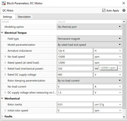
Controlled current source: A controlled current source is an electronic circuit that can adjust its output current in response to changes in a control signal. It is essentially a current source that can be "controlled" or "regulated" in some way. Controlled current sources are used to maintain a constant current level despite variations in load resistance or input voltage. They are commonly used in applications such as electronic test equipment, power supplies, and battery charging systems.
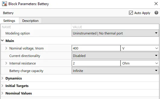
Battery: A battery is made up of one or more battery cells (electrochemical cells), each cell consists of anode electrode, cathode electrode, separator, electrolyte, terminals and an enclosure or case. In EVs high voltage battery is one the major component and the battery parameters have significant role on other component of the vehicle such as (i) Range of the vehicle (ii) Total weight
of the vehicle (iii) Total cost of the vehicle (iv) Torque of the motor (v) Torque of the regenerative braking.
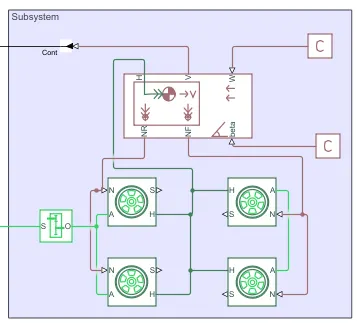
Subsystem of vehicle body
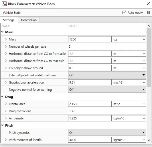
Vehicle body: The Vehicle Body block represents a two-axle vehicle body in longitudinal motion. The vehicle can have the same or a different number of wheels on each axle. For example, two wheels on the front axle and one wheel on the rear axle. The vehicle wheels are assumed identical in size. The vehicle can also have a center of gravity (CG) that is at or below the plane of travel. The block accounts for body mass, aerodynamic drag, road incline, and weight distribution between axles due to acceleration and road profile. Optionally include pitch and suspension dynamics. The vehicle does not move vertically relative to the ground. The block has an option to include an externally-defined mass and an externally-defined inertia. The mass, inertia, and center of gravity of the vehicle body can vary over the course of simulation in response to system changes.
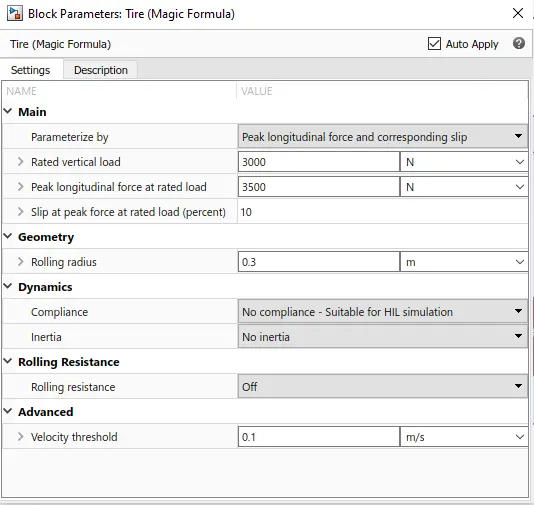
Tires: The Tire (Magic Formula) block represents a tire with longitudinal behavior given by the Magic Formula, an empirical equation based on four fitting coefficients. The block can model tire dynamics under constant or variable pavement conditions. To increase the fidelity of the tire model, you can specify properties such as tire compliance, inertia, and rolling resistance. However, these properties increase the complexity of the tire model and can slow down simulation. Consider ignoring tire compliance and inertia if simulating the model in real time or if preparing the model for hardware-in-the-loop (HIL) simulation.
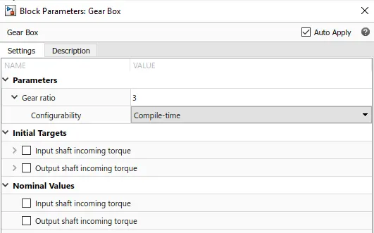
Gear box: The Gear Box block represents an ideal, nonplanetary, fixed gear ratio gear box. The gear ratio is determined as the ratio of the input shaft angular velocity to that of the output shaft.
Model parameters:
- Mass of the vehicle= 1200kg
- Gear ratio= 3
- Frontal area (Ae)= 2.153m^2
- Air density= 1.225kgm^3
- Wind speed= 0m/s
- Drag co-efficient= 0.39
- Max speed= 130km/hr = 36.11m/s
- Max acceleration= 2m/s^2
- Effeciency of system= 90%
Result
Total force= frictional force+ drag force+ normal force
Frictional force= frictional co-efficient*mass*9.81*cos(a)
= 0.0130*1200*9.81*1
= 153.036Nm
Drag force= 0.5*air density*Cd*frontal area*(Vvehicle-Vwind)^2
= 0.5*1.225*0.39*2.153*(36.11-0)^2
=670.60Nm
Normal force= mass*9.81*sin(0)
= 1200*9.81*0
=0
Total force= 153.036+670.60 = 823.64Nm
Motor power = (total force*max speed)/efficiency
= (823.64*36.11)/90% = 33kw
By inserting the calculated motor power in our DC motor block we get the following graph
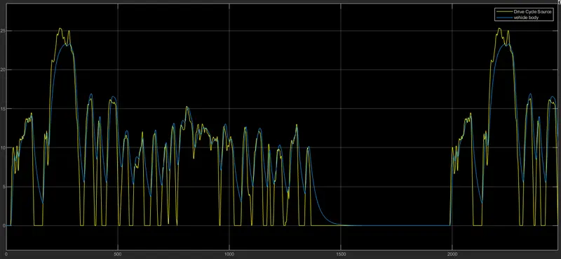
Conclusion: By detailed calculation and selection of design parameters of electric vehicle will help us in understanding fuel efficiency, speed, range and weight carrying capacity of the electric vehicle. From the model we have achieved an approximate distance of 6km.