Final Project: Design of an Electric Vehicle
PROJECT-
Create a MATLAB model of electric car which uses a battery and a DC motor. Choose suitable blocks from Powertrain block set. Prepare a report about your model including following:
Objectives:
1. System level configurations
2. Model parameters
3. Results
4. Conclusion
SOLUTION = ELECTRICAL VEHICLE DESIGN
electrical vehicle
- The electric vehicle uses battery source and electric motor for its propulsion.
- Electric vehicles have high efficiency compared to ICE. Losses in EV are also less.
- The motors used for propulsion of EV can be any of the below:
1.Permanent magnet synchronous motor
2. Three phase induction motor
3. BLDC motor
4. Switched reluctance motor
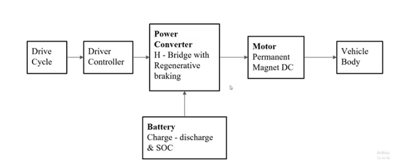
BLOCK DIAGRAM OF EV:
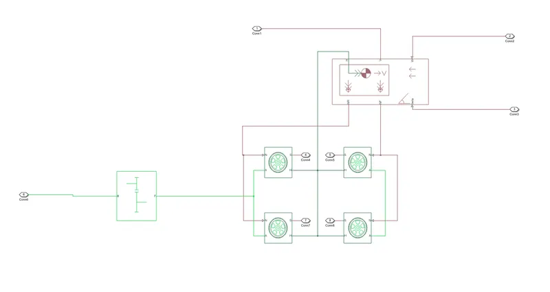
simulink model:
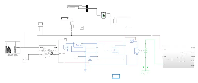
block used:
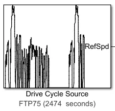
1) drive cycle
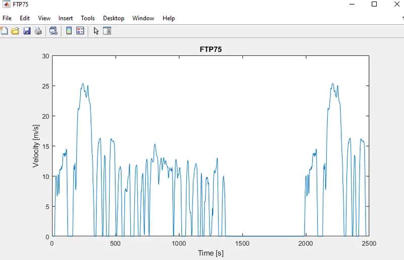
drive cycle plot:
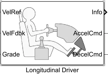
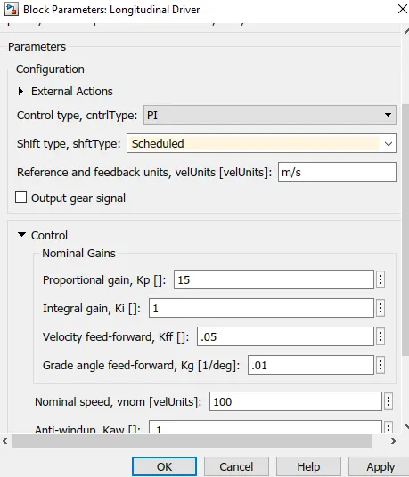
2) Longitudinal driver:
specification:
3) controlled voltage source: This block is used to maintain the specified voltage at its output regardless of the current flowinng through source.
4) controlled PWM voltage : Used to create pulse width modulated voltage.
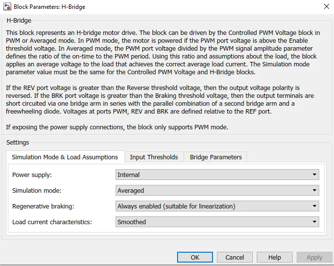
5) H-bridge: Used to change the polarity of voltage applied across DC motor so as to run the motor in forward and reverse direction as per input command.
6) Current sensor block: Used to measure current flowing through H- bridge.
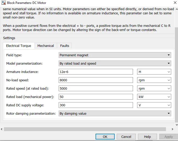
7) DC motor : To convert electrical energy to mechanical energy. In regenrative braking motor the mechanical energy gets converted into electrical energy.
8) vehicle body: The block represents a two axel vehicle body in longitudinal motion. The block accounts for body mass, aerodynamic drag, road incline weight distribution between axel due to acceleration, road profile.
9) tire:
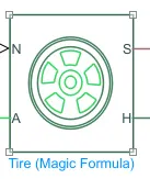
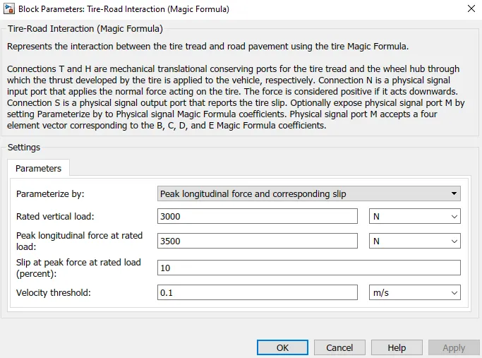
- used to model a tire with longitudinal behavior given by equation based on four fitting coefficients.
- The block can model tire dynamics under constant or variable contact surface conditions.
Input Port:
- N - Normal force acting on tire, positive when force is acting downwards/towards the contact surface,
Output Port:
- S - Slip value relative to tire and surface of contact.
Conserving Ports:
- H - represents wheel hub which transmits thrust generated by the wheel to the body of the vehicle.
- A - represents axle on which the tires are mounted.
specification:
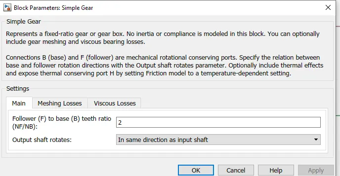
10) simple gear:
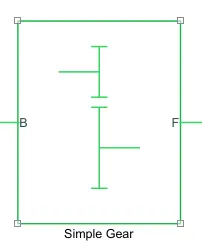
Conserving Ports:
- B - port associated with input shaft (motor shaft)
- F - port associated with ouput shaft (axle / differential)
specification:
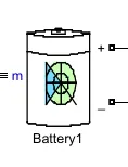
11) battery
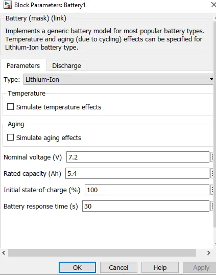
specification
output :
drive cycle & vehicle velocity:
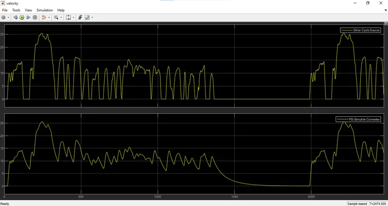
- The vehicle velocity plot is following the drive cycle velocity curve, it means the controller trying to minimize the error in between them.
- There is some difference in drive cycle and vehicle velocity, this is beacause of inertia of vehicle mass.
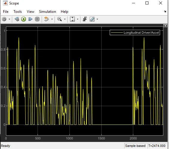
longitudanal driver acceleration:
battery soc , current & voltage:
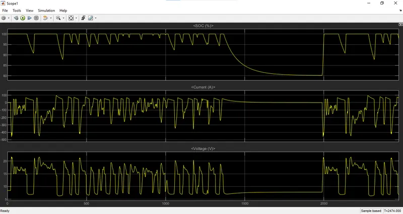
conclusion : The model was succesfully ran for simulation under the standard FTP75 drive cycle. The results have been properly analyzed.
Also, learnt quite a lot of interesting things like -
- how to model an EV and carry out a real time simulation
- how a motor controller works and what role it plays in the control of the electric motor
- how to calculate the SOC of the battery
- different powertrain blocks provided by simulink which can be used to simulate a vehicle model.