Project - Speed Control of a Direct Current (DC) motor
AIM =
In this project, a Simulink model for the DC motor will be first developed per the schematic shown in Figure 1.
Use the Proportional, Integral, and Derivative (PID) control design knowledge gained in the training to design, develop and test a controller to maintain a desired speed for the motor.
ANSWER
- Here the Speed control of a DC motor is either done manually by the operator or by means of an automatic control device.
- This is different to speed regulation where the speed is trying to be maintained or regulated against the natural change in speed due to a change in the load on the shaft
-
so the speed can be varied by changing:
- The terminal voltage of the armature V
- The external resistance in armature circuit Ra
- The flux per pole
-
So Terminal voltage and external resistance involve a change that affects the armature circuit while flux involves a change in the maginetic field
-
so Therefore speed control of DC motor can be classified into:
1] armature control method 2]field control method
simulink model :
intiallay dc motor simulink model is build. with following parameter
J = 0.01; %moment of intertia
B = 0.1; % motor viscous friction
Km = 0.01; %back emf
Kt = 0.01; %motor torque constanat
Ra = 1; %armature resistance
La = 0.5; %armature inductance
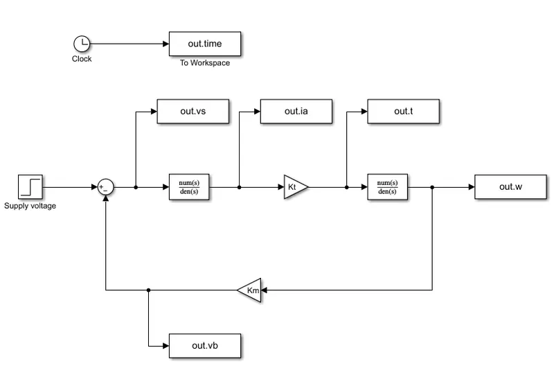
output of plot :
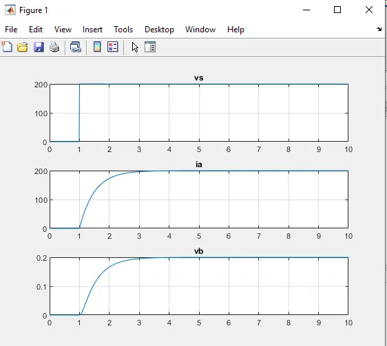
1]supply voltage 2]armature current 3]back emf
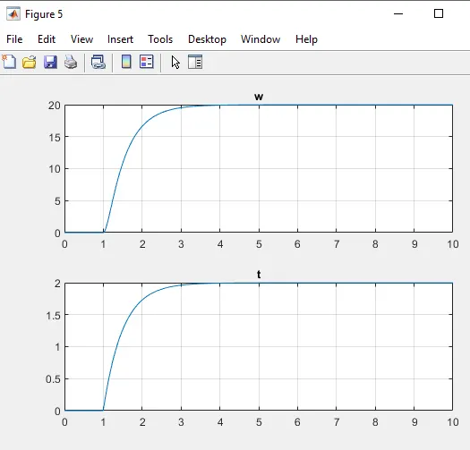
4] speed 5]torque
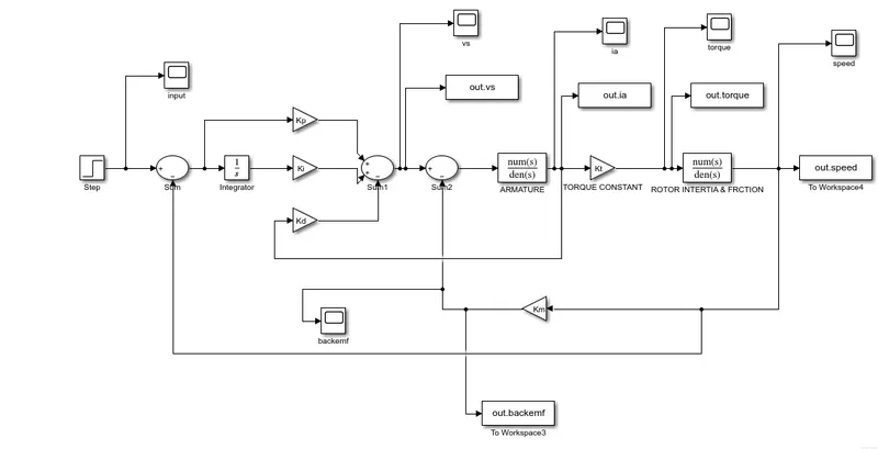
After that in a DC motor PID controller are use :
%% design parameter of DC motor
J=0.01;%%moment of intertia of the rotor in kg-m^2
B=0.1;%% motor viscous friction constanatin
Km=0.01;%% back emf constant
Kt=0.01;%% motor torque constant
Ra=1.0;%% resistance ohfarmature circuit
La=0.5;%%inductance of armature circuit
%% design of PID controller
A=[-B/J Kt/J; -Km/La -Ra/La];
B_MOTOR=[0 ; 1/La];
%% placement of pole
fn=1.0;
wn=2*pi*fn;
zeta=0.5;
p1=-zeta*wn+wn*sqrt(zeta^2-1);
p2=-zeta*wn-wn*sqrt(zeta^2-1);
P=[p1;p2];
K=place(A,B_MOTOR,P);
Kp=38.3133;
Kd=-2.8584;
Ki=1;
schematic of PID model with DC motor:
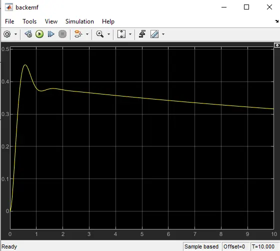
output plot:
supply output:
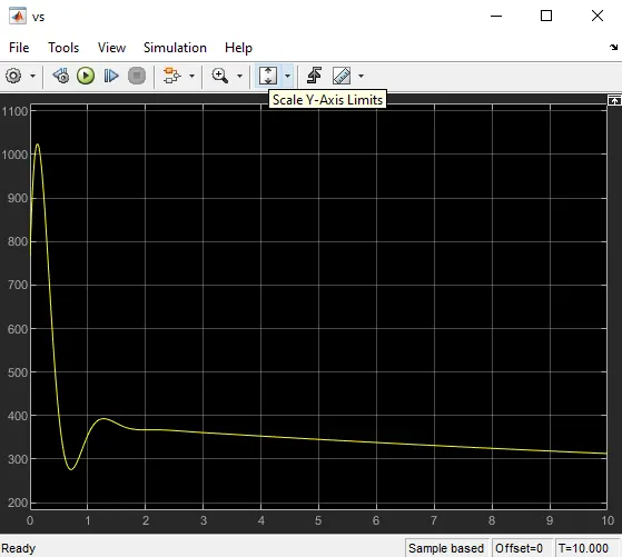
2]armature current
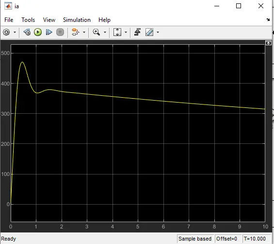
3]torque
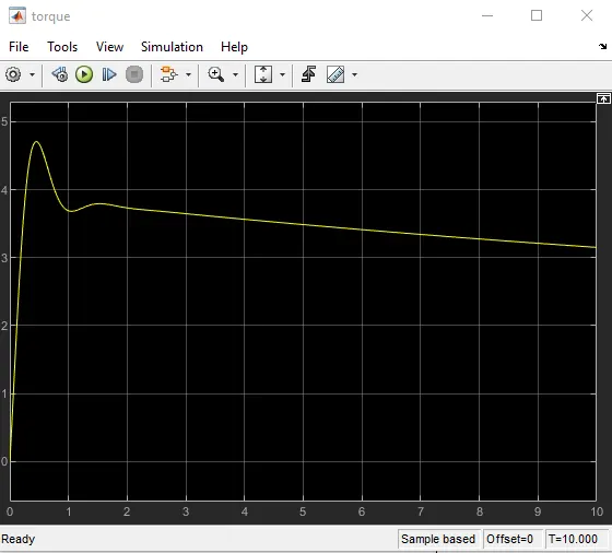
4]speed
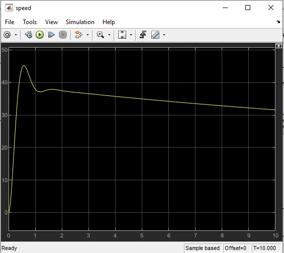
5]back emf
conclusion:
In this project we learned how to use proportinal, derivative and integral controller in DC motor and study the different plot i.e armature current,speed, torque, speed and back emf.