Week-6 Challenge: EV Drivetrain
1) Which types of power converter circuits are employed in electric and hybrid electric vehicle?
ans=
There are 4 types of power converter circuits that are employed in EV and HEV:
1. AC to DC Converter
2. DC to DC Converter
3. DC to AC Converter
4. AC to AC Converter
- DC - AC Converters(Inverter):
The DC - AC Converter is also known as Inverter circuit and it is widely used in the UPS Home application. The DC - AC Converter is used to convert the DC power to a suitable AC power to drive the motor drive train in the Electric and Hybrid Electric Vehicles.
- AC - DC Converters(Rectifier):
The AC - DC Converter is also known as Rectifier circuit and it is widely used in Mobile and Laptops charger application. The AC - DC Converter is used to convert the AC power to DC power which is used in On-board charger in the Electric and Hybrid Electric Vehicles. This converters will help to charge the battery packs in EVs and HEVs by converting the AC power source from charging station.
- DC - DC Converters(Chopper):
The DC - DC Converter is also known as Chopper circuit and it is widely used in Electric Trains. The DC - DC Converter is used to convert the DC power at one level to DC power at another level and it is used to deliver power for the accessories used in the Electric and Hybrid Electric vehicles.
2) An Electric Vehicle's powertrain with 72V battery pack in shown in the diagram below. The duty ratio for acceleration operation is 'd1' and for the braking operation the duty ratio is 'd2'.
The other parameters of the electric vehicle is given below,
Motor and Controller Parameters:
Rated Armature voltage= 72 V
Rated armature current= 400 A
Ra= 0.5Ω, KΦ= 0.7 Volt second
Chopper Switching frequency= 400 Hz
The vehicle speed-torque characteristics are given by the below equation

What is EV steady state speed if duty cycle is 70%?
ANS=
Formula: T= (V.k/R)-(k^2.w)/R
The vehicle torque-speed characterictics is given by: T= 24.7 + (0.0051)w^2
Comparing two equations:
24.7+(0.0051)w^2 = (72*0.7*0.7)/0.5-(0.7^2/0.5)*w
w^2+192.15*w-8992.15.15=0
w=38.95 rad/sec
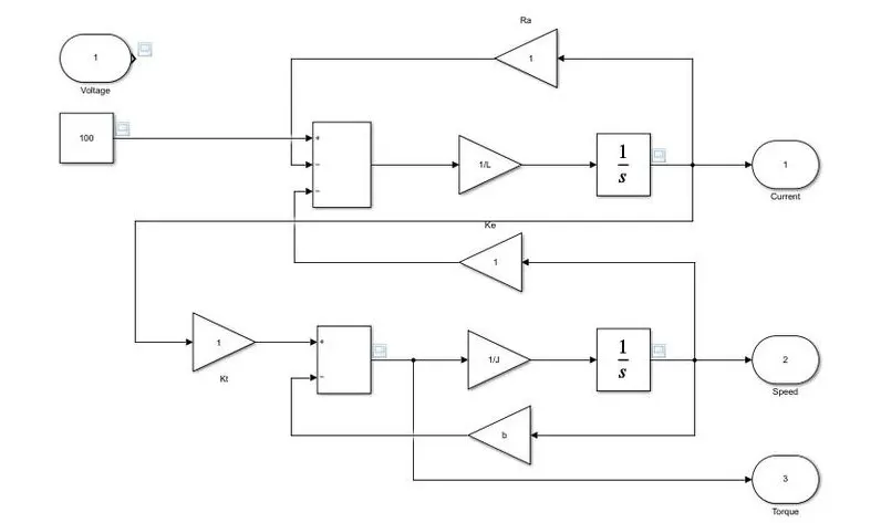
3) Develop a mathematical model of a DC Motor for the below equation using Simulink.
ω">ωω= V/Kϕ">ϕϕ -Ra/Kϕ">ϕϕ^2 .T
ANS= simulink model
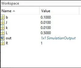
workspace:
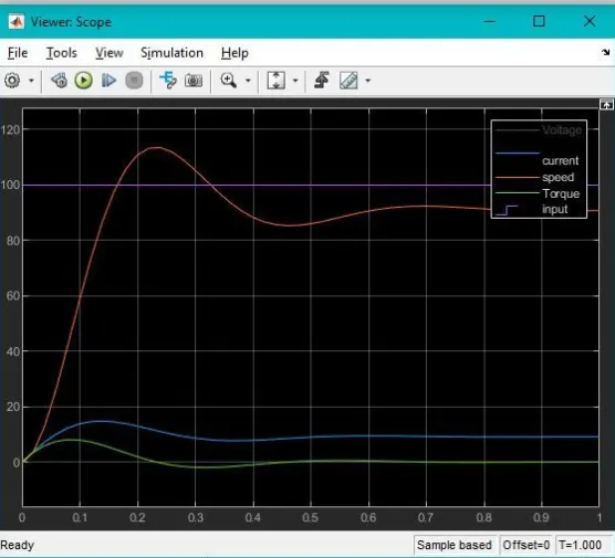
scope output:
4) Refer to the blog on below topic:
Induction Versus DC brushless motors by Wally Rippel, Tesla
Explain in brief about author’s perspective.
ANS=
The author's perspectives are as follows:
-Unlike to DC brushless rotor, the induction rotor has no magnets just stacked steel laminations with buried peripheral conductors that form "shorted structure".
- When 3 phase induction motor is connescted to utility type 3 phase power, torque is produced at the outset; the motor has ability to start under load. Induction motors are directly compatible with conventional utility power is the main reason for their success. In constrast, a brushless DC motor produces no starting torque when directly connected to fixed frequency utility power.
- With brushless DC, as machine size grows, the magnetic losses increses proportinaly and load efficiency drops. With induction, as machine size grows, losses do not necessarily grow. Thus induction drives may be the favoured approach where high performance is desired, peak efficiency will be little less than with DC brushless, but average efficiency may actually be better.
-In conclusion, DC brushless drives will likely continue to dominate in the hybrid and coming plug in hybrid markets, and tha inductoon drives will likely maintain dominance for the high performance pure electrics.