Final Project: Design of an Electric Vehicle
Project - 2
Modelling of an electric car
Aim :
Create a MATLAB model of electric car which uses a battery and a DC motor. Choose suitable blocks from Powertrain block set. Prepare a report about your model including following:
Objectives:
1. System level configurations
2. Model parameters
3. Results
4. Conclusion
Theory :
An Electric Vehicle (EV) is a vehicle that uses one or more electric motors or traction motors for propulsion. An electric vehicle may be powered through a collector system by electricity from off-vehicle sources, or may be self-contained with a battery, solar panels, fuel cells or an electric generator to convert fuel to electricity. EVs include, but are not limited to, road and rail vehicles, surface and underwater vessels, electric aircraft and electric spacecraft.
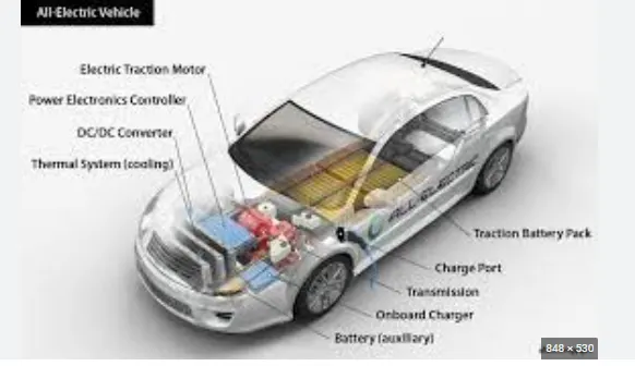
- EVs have no need for the fuel engine and gear transmission, the two of the most crucial components for internal combustion vehicles.
- An electric powered car has three primary components - Battery, motor controller, and the electric motor.
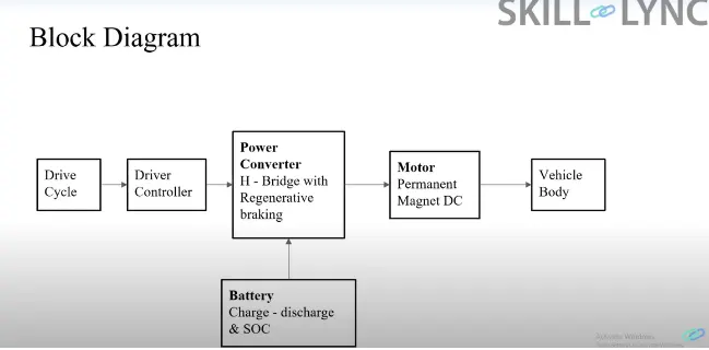
Block diagram :
Components :
The main components of modelling an EV are:
- Vehicle body
- Motor & motor controllers
- Power converters
- Batteries
- Drive cycle
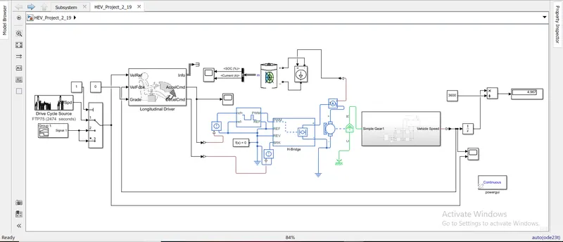
Simulation of electric vehicle model:
Subsystem of chasis :
Tire :

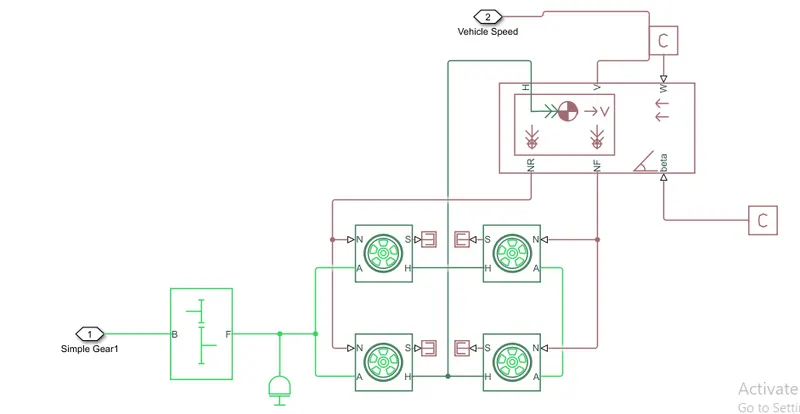
- Totally there are 4 tires present in the vehicle.
- Rolling resistance force is created in the tire when the vehicle moves.
- Front 2 tires is connected with front axle and rear tyre is connected with rear axle,
- There are totally 4 input ports, they are
- N - Phisical signal input port that applies normal force applied on the tire.
- S - Phisical signal output port that reports the tire slip.
- A - mechanical rotational conversing port for the wheel axle.
- H - Thrust developed by the tire.
Vehivcle body:
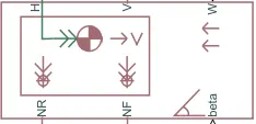
- Body chasis is the important part of each and every vehicle.
- H - mechanical translational conserving port hub
- V - actual output translational velocity of the vehicle.
- W - headwind speed
- NR - correspond to the output ports for nomral reaction forces on rear axle wheels respectively.
- NF - correspond to the output ports for nomral reaction forces on front axle .
- beta - is the road inclination angle.
The geometric parameters of the vehicle are given as
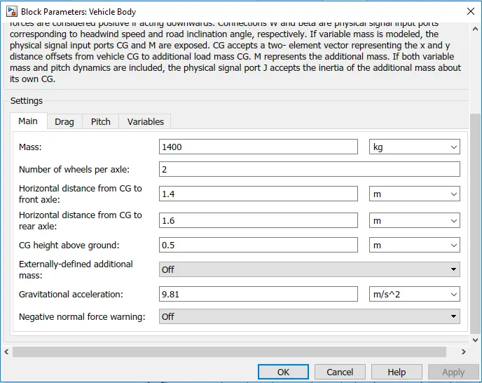
- Total mass is 1400 kgs.
- Other parameters are mentioned below.
Drag:
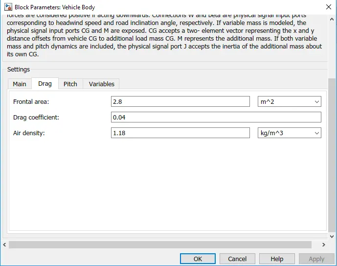
- Drag co-efficient is 0.04.
- Frontal area is 2.8 m^2.
Gear ratio:
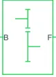
- A simple gear block is used to connect the motor to the rear axle of the vehicle.
- It represents the gearbox which connects the input shaft to the base gear and ouput from the foller gear.
Conserving Ports:
- B - port associated with input shaft (motor shaft)
- F - port associated with ouput shaft (axle / differential)
Simple Gear Parameters:
- Gear ratio and output direction is modified.
- Meshing loss is kept constant and gear is having a constant efficiency throughout the simulation.
- Viscous losses and faluts are kept at default conditions.
DC motor:
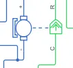
This is the DC Motor which would give the rotational power to the wheels and become the sole power generation source.
The DC Motors terminals are connected as mentioned below,
+ = Electrical signal to the motor Positive Terminal
- = Electrical signal to the motor Negative Terminal
R = Casing of the Motor connected with the Mechanical Rotational Reference Block
C = Rotor Case connected to the Mechanical Rotational reference
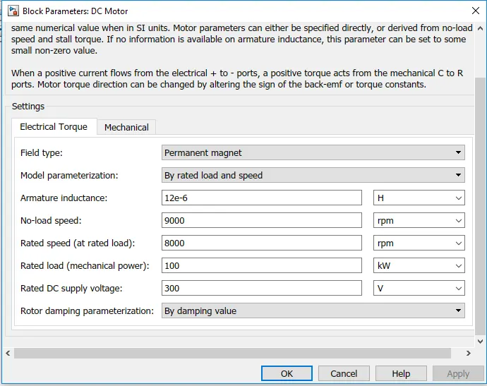
The geometric parameters of the DC motor are given as
Mechanical of dc motor:
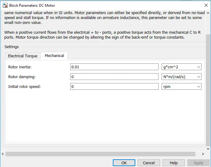
Here the momoent of inertia is taken as 0.01 gcm^2
H - bridge:
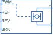
The H-Bridge helps in controlling the power that is input according to the requirement. The output provided are converted voltage as per the controlled parameters.
The geometric parameters of the H-bridge are given as
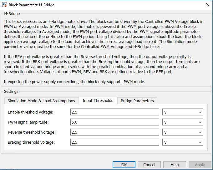
Bridge parameters:
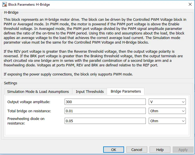
Output voltage amplitude is 300v.
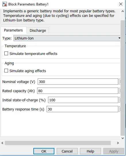
Battery:

The battery is connected as the power source to the model so that the power could be generated and the same power is transmitted accordingly to all the operating sources.
The terminals connected are to,
+ = The positive terminal of the operating sources
- = The negative terminal of the operating sources.
PWM controller:

- This block craetes voltage across the PWM and REF port.
- The output voltage is zero when the puse is low and equal to the output voltage amplitude parameter when high.
- Duth cycle is set by input value.
ref+ = Reference Positive connected with the Acceleration Commands from the Driver Model
ref- = Reference Negative connected with the Deceleration Commands from the Driver Model
PWM = PWM connected directly to the H-Block
REF = REF connected directly to the H-Block
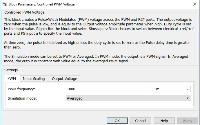
PWM frequency is setted to 1000Hz.
Longitudinal driver:
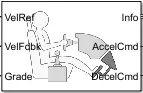
This block is used to convert the speed data into code for acceleration and deceleration.
- Velocity Reference - Drive Cycle
- Velocity Feedback - Distance Calculation
- Grade - Constant 0
- Info - Not Connected
- Acceleration Command - Controlled PWM Source
- Deceleration Command - Brake in H-Bridge to maintain the speed according to the Drive Cycle.
Drive Cycle :
starting with the Drive Cycle,let consider a FTP75 for the operation of the Cycle in which the test duration would be 2474 seconds.
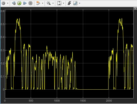
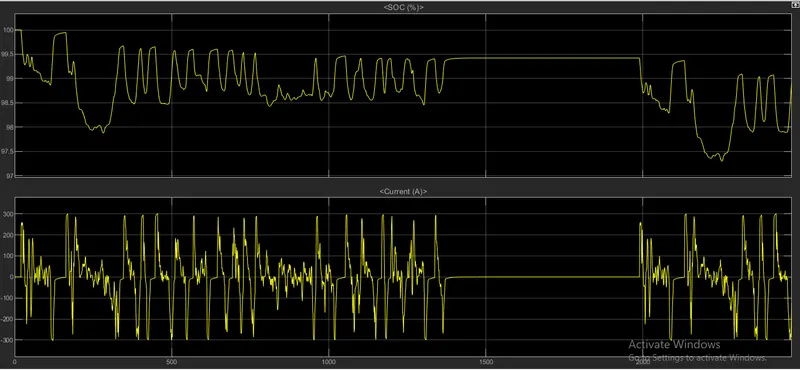
output of battery:
Reference Speed v/s Actual vehicle speed:
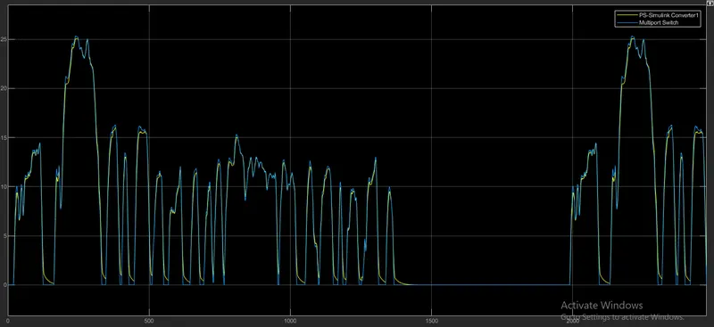
Actual speed is compared to the reference speed of the drive cycle.
Vehicle is running at the constant from 1400 to 2000 seconds.