Final Project: Design of an Electric Vehicle
"Final Project: Design of an Electric Vehicle"
Aim:
To create a MATLAB model of electric car which uses a battery and a DC motor. Choose suitable blocks from Powertrain block set. Prepare a report about your model including following:
Objectives:
1. System level configurations
2. Model parameters
3. Results
4. Conclusion
Introduction:
Earth is heading for a disaster. Humanity is having a material and irreversible impact on Earth - we've destroyed half of the world's forests and will soon wipe out most of the rest. The human and economic consequences of such changes will make Covid-19 look like an irrelevance of the 21st century.
Due to such activities, every year this planet's temperature is rising due to global warming, which is a direct consequence of the release of harmful gases such as carbon dioxide. An enormous amount of carbon dioxide is released from the cars we drive. One of the most significant ways of preserving our planet such that it remains livable for our future generation is to minimalize this release of `CO_2`. Powering vehicles through hybrid technology, going all electric or through alternate sources (such as hydrogen) is an excellent way of fighting climate change. Aren't we responsible to preserve the planet that we have constantly destroyed since the beginning of time? Here are a few consequences that have already happened, and its only going to get worse unless we start doing our part.
- Texas power grid failure 2021: it is a misunderstanding that climate change only refers to the earth getting warmer each other. This freak snowstorm in Texas may not seem like a harbinger of global warming, but a growing body of research links climate change with the occurrence of the so-called polar vortex. Scientists say warming in the Arctic, where temperatures are rising faster than anywhere else on the planet, may be weakening the jet stream that typically keeps cold air deep in the northern hemisphere. A weakened jet stream allows freezing air to drift down to lower latitudes, hence affecting areas like Texas which is among the lowest (in terms of latitudes) points in the US.
- Near-record melting of Arctic sea ice 2019: With the ice gone, the sun’s energy will instead be absorbed by the ocean. Losing the ice will be equivalent of adding 25 years’ worth of greenhouse gas emissions at the current rate humans are burning fossil fuels.
- Australia's apocalyptic fire season 2019: The record heat and dryness created some of the most apocalyptic early-season fire activity ever witnessed in the country, with at least 21 people killed, 15 million acres burned, and 3500 structures destroyed. Thousands of people had to flee to the beach to avoid incineration and be given supplies and evacuated by military ships and aircraft.
For more - https://climate.nasa.gov/effects/
Electric vehicles aren't fully clean either because of the pollution generated by the mining process of batteries and the facilities to process them. In addition, the electricity generated to power these vehicles currently coming from the grid is from non-renewable resources like coal and natural gas. However, they are still a lot cleaner than Internal Combustion Engine cars that still hold an overwhelming majority of the market, and this is what needs to change. The transition to clean and sustainable energy needs to be accelerated.
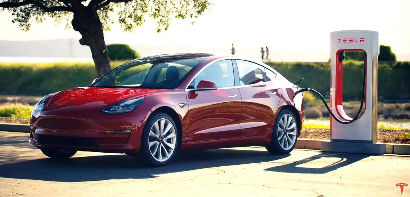
This project presents a MATLAB/SIMULINK model of an entirely electric vehicle (EV).
The main components of an EV are:
- Battery
- Motor controller/Power converter
- Motor/Generator
- Vehicle body (including transmission, wheels)
This is how an EV is typically modeled. A battery provides electrical power to the motor, which converts it to mechanical power and powers the vehicle. However, if the battery is directly connected to the motor, the vehicle would be running at constant speed as there is no control. A motor controller is a power converter that bridges this gap and controls the speed and voltage provided to the motor, so the vehicle performance can be controlled.
To run a simulation, a reference always needs to be provided to the system to know what it is working towards. Without a reference drive cycle, the system would not know when to accelerate, brake, or stop the vehicle, and hence the performance of the entire system cannot be evaluated as we will never know how effectively everything is working.
Understanding EV Components:
Electric Vehicle's working mechanism is different from that of internal combustion engines. Here we explore the main components of EV as a way to explain its essential characteristics.
Electric Vehicles(EVs) are increasingly becoming a part of modern life; their tremendous fuel economy, eco-friendliness, and smooth driving feel have appealed to many conscious modern consumers. EVs are quite different from traditional vehicles with internal combustion engines. From the basic mechanism and operating principle to methods of usage and maintenance, the two categories diverge in many, many aspects. Understanding those differences, ideally, would be the first step for a consumer beginning to gauge his or her interest in EVs. A venture into a new field of knowledge is always a challenge, but given the unmistakable trend toward the electric, there is no reason to shy away. As the first part of our “EV A to Z Encyclopedia” series, here we explore the secrets of EV mobility by reviewing its crucial components and functions.
As is well known, EVs use the electricity saved in the battery to cycle the motor and generate the power necessary for driving.
This is the biggest difference to internal combustion vehicles, in which the engine exhausts fossil fuel to generate that power. As such, EVs have no need for the engine and transmission, the two of the most crucial components for internal combustion vehicles. Instead, EVs carry several components for electric power: the motor, the battery, the on-board charger, and the Electric Power Control Unit(EPCU). All are essential components to achieve the conversion of the battery’s electricity into the kinetic force that drives the EV forward.
Motor:
The motor converts electric energy into kinetic energy that moves the wheels. The advantage of using the motor instead of an engine is numerous: first, the noise and the vibration we typically associate with cars are minimized. Many passengers riding EVs for the first time are surprised by just how quiet and comfortable the ride feels. Moreover, the EV powertrain is smaller than the engine, thus providing lots of additional space for efficient vehicle design—like expanded cabin space or storage.
The motor is also in part an electric generator—it converts the kinetic energy generated while in neutral gear(e.g. while the car is going downhill) into electric energy saved to the battery. The same energy-saving idea applies when the car is reducing its speed, culminating in the so-called “regenerative braking system.” Some of the Hyundai Motor Group’s EVs are equipped with a mechanism that can control the levels of regenerative braking via paddle shifters on the steering wheel, which not only improves the fuel economy but also adds an interesting and fun element to driving.
Reducer:
The reducer is a kind of transmission in that it serves to effectively convey the motor’s power to the wheel. But it carries the special name—reducer—for a reason: the motor has a far higher RPM than that of an internal combustion engine, so whereas transmissions change the engine RPM to match the driving circumstance, the reducer must always reduce the RPM to an appropriate level. With the reduced RPM, the EV powertrain can take advantage of the resulting higher torque.
Battery:
The battery stores electrical energy and is the equivalent of a fuel tank in an internal combustion engine. The maximum driving distance of an EV is often determined by the battery capacity—the higher the capacity, the higher the driving distance. In that light, increasing the capacity may seem an obvious choice, since high driving distance reduces the annoying need for frequent stops at charging stations. But the choice actually isn’t so obvious, because the battery’s size and weight also have large implications on vehicle performance. The larger and heavier battery takes away from cabin/storage space and worsens the energy efficiency and fuel economy. The best way to optimize performance, then, is to maximize the battery’s energy density—that is, having a small, lightweight battery that stores as much electric energy as possible.
Thanks to the recent advancements in battery technology, the more recent EVs boast significant upgrades over older models in terms of battery density and driving distance. The Kia Soul Booster EV, for example, is equipped with a 64kWh lithium-ion battery that lasts for the max distance of 386 km(according to Korean certification standards). The battery life also saw significant improvements: assuming a normal pattern of usage, the Soul Booster EV’s battery can last through the entire life cycle of the vehicle. To explain in greater detail, understand first those lithium-ion batteries on EVs show battery life that varies with the charging pattern. If the charging pattern is such that the entire battery is exhausted and recharged to full, the battery can be used for 1,000 charges; if the battery is used to half(50%) and recharged, 5,000 charges; if one-fifth of the battery is used(20%) and recharged, 8,000 charges. This means, that if the Soul Booster EV is driven for 77 kilometers a day(equivalent to 20% of the max driving distance) and recharged every night, the battery can last for 8,000 days(22 years).
Battery Management System(BMS):
The Battery Management System(BMS) manages the battery’s many cells so that they can operate as if they are a single entity. The EV’s battery consists of as little as tens to as many as thousands of mini-cells, and each cell needs to be in a similar condition to the others in order to optimize the battery’s durability and performance.
Most often, the BMS is built into the battery’s body, though sometimes it is incorporated into the Electric Power Control Unit(EPCU). The BMS mainly oversees the cell’s charge/discharge status, but when it sees a malfunctioning cell, it automatically adjusts the power status of the cell(on/off) through a relay mechanism(the conditional mechanism for opening/closing other circuits).
Battery Heating System:
In lower temperatures, the battery sees a decrease in both charging capacity and speed. The battery heater exists to keep the battery within the ideal temperature range, preventing seasonal performance decreases and maintaining the max driving distance. The system also functions while charging, ensuring the charge's efficiency.
On-board Charger(OBC):
The On-board Charger(OBC) is used to convert Alternating Current(AC) from slow chargers or portable chargers used on home outlets into Direct Current(DC). This may make the OBC look similar to the traditional inverter, but they differ crucially in function; the OBC is for charging, and the inverter is for acceleration/deceleration. Incidentally, the OBC is not needed in fast-charging, since fast chargers already supply the electricity in direct current.
Electric Power Control Unit(EPCU):
The Electric Power Control Unit(EPCU) is an efficient integration of nearly all devices that control the flow of the electric power in the vehicle. It consists of the inverter, the Low voltage DC-DC Converter(LDC), and the Vehicle Control Unit(VCU).
Inverter:
The inverter converts the battery’s DC into AC, which then is used to control the motor speed. The device is responsible for executing acceleration and deceleration, so it serves a crucial part in maximizing the EV’s drivability.
Low voltage DC-DC Converter:
The LDC converts the high voltage electricity from the EV’s high-voltage battery into low-voltage(12V) and supplies it to the vehicle’s various electronic systems. All electronic systems in the EV use electricity in low voltage, so the high voltage in the battery must be converted first to be useful for these systems.
Vehicle Control Unit:
As the control tower of all electric power control systems in the vehicle, The VCU is arguably the most important component of the EPCU. It oversees nearly all the vehicle’s power control mechanisms, including the motor control, regenerative braking control, A/C load management, and power supply for the electronic systems.
Different Types of Electric Vehicles:
Battery Electric Vehicles (BEVs):
Battery electric vehicles, or BEVs, are often just called electric vehicles. Unlike HEVs and PHEVs, BEVs are powered entirely by batteries, with a full-electric drivetrain.
In fact, that’s one of the advantages of battery electric vehicles, their simplicity. There are so few moving parts in a battery electric vehicle that very little maintenance is required. There are no oil changes or tune-ups needed, and the savings from not having these maintenance expenses can add up to significant savings over the lifetime of the vehicle.
Since battery electric vehicles rely solely on the amount of stored electricity in their batteries, it’s even more important to be able to recharge them quickly, than it is for plug-in hybrid models. Therefore it’s important to choose a home charging solution that can fully recharge your BEV as quickly as possible, so you can enjoy the vehicle to its fullest.
Most battery electric vehicles come standard with a 120 volt level 1 charger, which can take very long to recharge the vehicle. That’s because battery electric vehicles have much larger batteries than HEVs or PHEVs do. Take a look at the graph below to see the battery size, driving range and charging times of four of the popular battery electric vehicles available today.
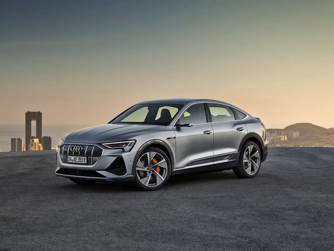
Fig: AUDI e-Tron Sportback
Plug-in Hybrid Electric Vehicle (PHEV):
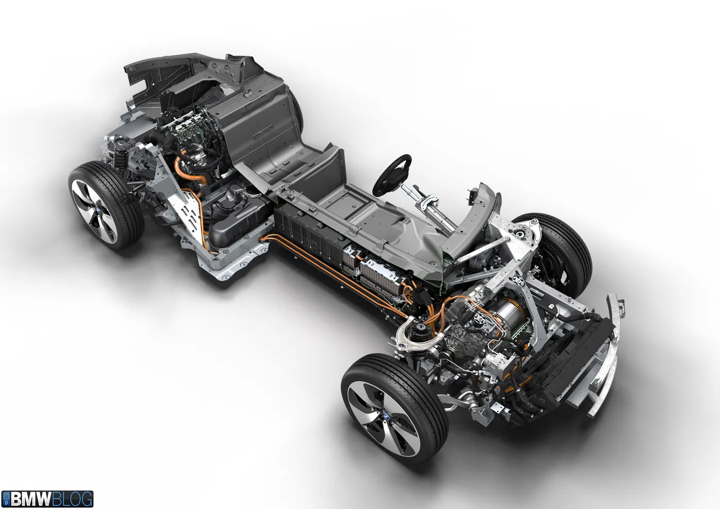
A plug-in hybrid electric vehicle (PHEV) is a hybrid electric vehicle whose battery pack can be recharged by plugging a charging cable into an external electric power source, in addition to internally by its on-board internal combustion engine-powered generator. Most PHEVs are passenger cars, but there are also PHEV versions of commercial vehicles and vans, utility trucks, buses, trains, motorcycles, mopeds, and even military vehicles.
Similar to all-electric vehicles (BEVs), PHEVs displace greenhouse gas emissions from the car tailpipe exhaust to the power station generators powering the electricity grid. These centralized generators may be of renewable energy (e.g. solar, wind, or hydroelectric) and largely emission-free, or have an overall lower emission intensity than individual internal combustion engines. Compared to conventional hybrid electric vehicles (HEVs), PHEVs have a larger battery pack that can be charged from the power grid, which is also more efficient and can cost less than using only the on-board generator, and also often have a more powerful electric output capable of longer and more frequent EV mode driving, helping to reduce operating costs. A PHEV's battery pack is smaller than all-electric vehicles for the same vehicle weight (due to the necessity to still accommodate its combustion engine and hybrid drivetrain), but has the auxiliary option of switching back to using its gasoline/diesel engine like a conventional HEV if the battery runs low, alleviating range anxiety, especially for places that lack sufficient charging infrastructure.
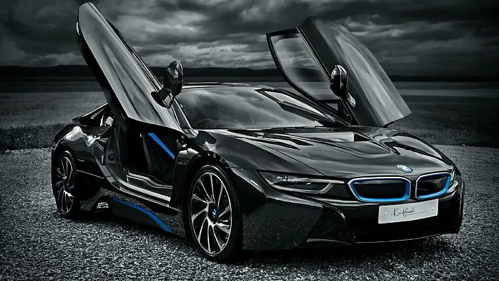
Fig: BMW i8
Hybrid Electric Vehicles (HEV):
Hybrid electric vehicles are typically referred to as “hybrids,” and although the technology has been around for decades, the cars didn’t really have material market penetration until 1997 when Toyota introduced the Prius. Since then, the Toyota Prius has been the world’s best-selling car and the most recognizable hybrid electric vehicle with its Prius battery. However, there are a number of hybrid models on the market today including the Kia Optima Hybrid, Ford Fusion Hybrid, Kia Niro, Hyundai Ioniq HEV, and several others.
Hybrid electric vehicles combine a conventional internal combustion engine with an electric propulsion system. The internal combustion engine does most of the work, while the electric motor assists the engine, with its main purpose being to increase the fuel economy.
Hybrids do not have the ability to plug in and recharge from the grid, so they use their internal combustion engines and regenerative braking systems to recharge their propulsion vehicle batteries. Most hybrids do not have the ability to propel the car on battery power alone and must have the combustion engine running whenever the vehicle is moving. However, there are a few hybrids that can propel the vehicle for a few feet at low speeds, before the combustion engine needs to turn on and assist.
Hybrid electric vehicles have better fuel economy and a lower total cost of ownership when compared to similar conventional cars, however, they usually also cost more to purchase initially.
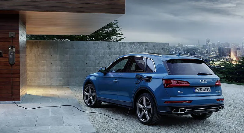
Fig: AUDI Q5 Quattro Hybrid
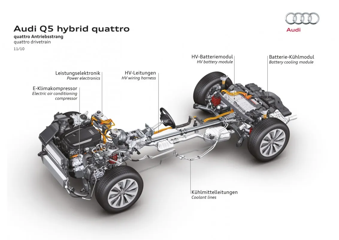
Now coming to my project,
Requirements:
Here, We have taken the Technical specifications of Mercedes Benz EQS 450+
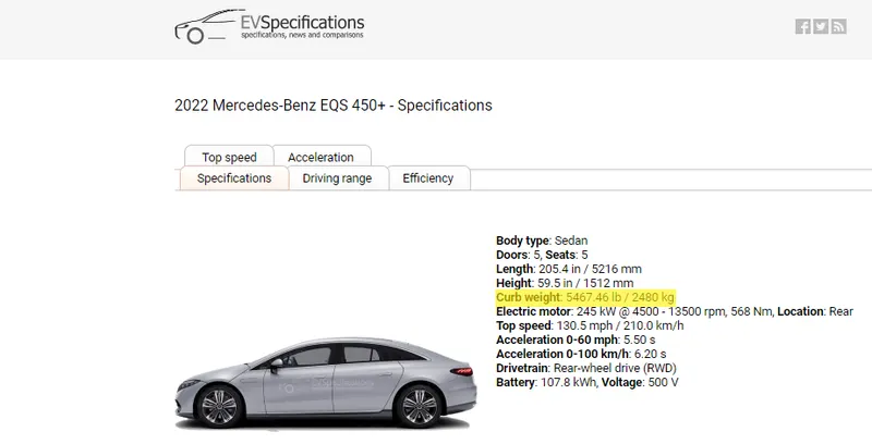
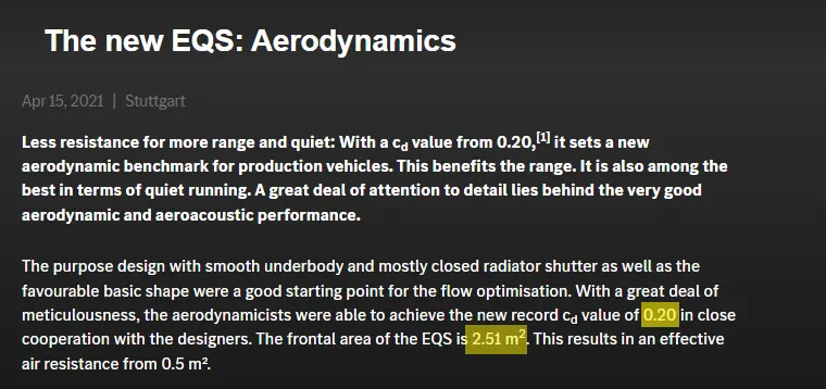
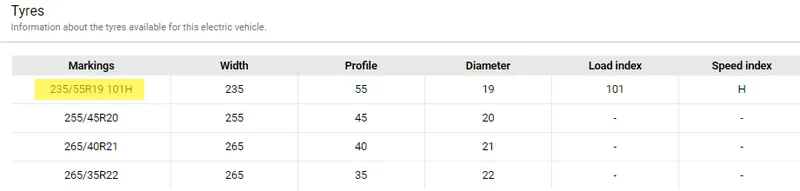
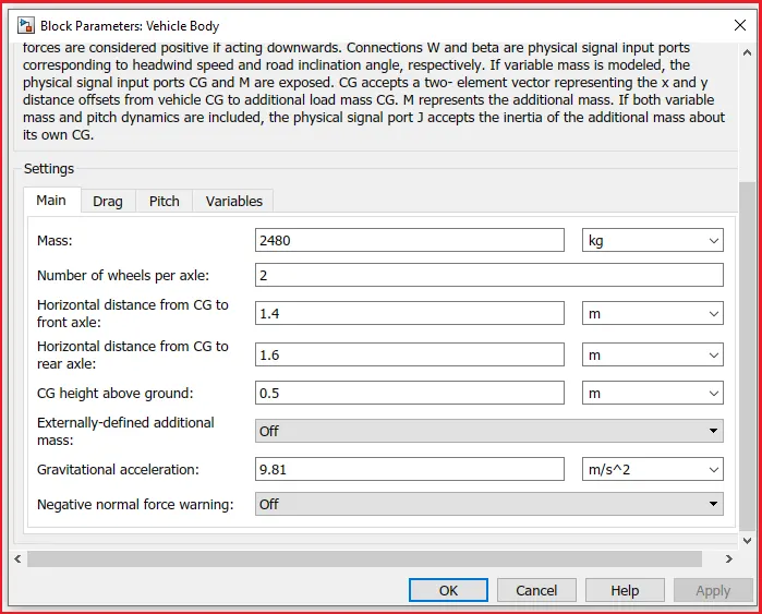
Total weight of vehicle = 2480kg
Top speed = 210 kmph
Frontal Area of vehicle = 2.51 `m^2`
Drag Coefficient = 0.2
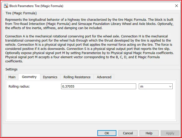
Rolling Radius = 0.37055 m (Calculated from Tire Specifications)
System level configuration and their Parameters:
The system-level configuration deals with the control of the entire EV. The simple block diagram of an entire EV will consist of battery, Dc motor and its controlling unit, Transmission system, and wheels.
Block Diagram for EV Modeling
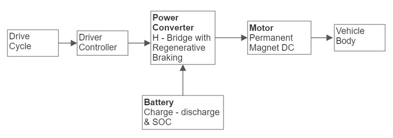
The block diagram is a simple layout of an EV. In the Matlab model, we are going to describe each and every block individually.
The design of an EV is done with a required battery package and a desired dc motor in the Simulink. The modeling of an EV is done using Simulink to describe the complete working of the vehicle.
Simulink Model:
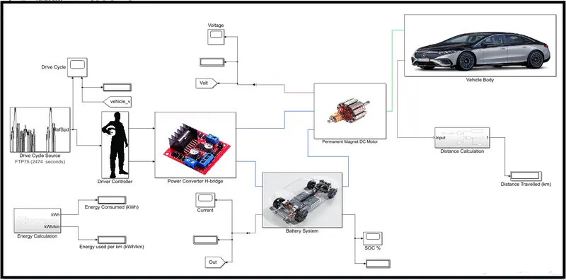
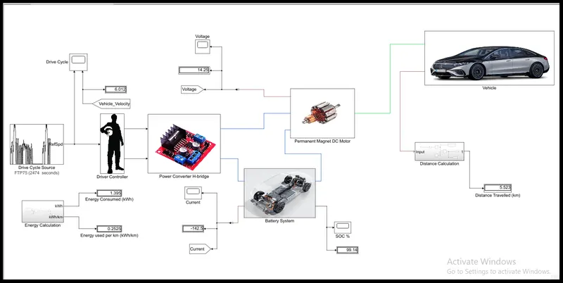
The above block diagram is used to stimulate a EV. The model consists of,
1. Vehicle body subsystem
2. Dc motor
3. Power Converter
4. Driver Controller
5. Drive cycle
6. Battery System
7. Distance Calculation
8. Energy Calculation
Now we can see about the component level details of the block used in the modeling of the EV
1) Vehicle Body Subsystem:
In the vehicle body subsystem, we are taken a vehicle body connected with a simple gearbox and Four tires.
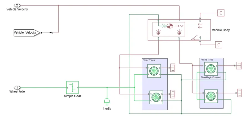
Simple Gear:
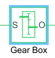
Represents a fixed-ratio gear or gearbox. No inertia or compliance is modeled in this block. We can optionally include gear meshing and viscous bearing losses.
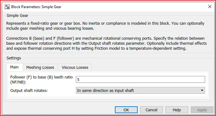
Here the gear ratio is given as 5 and the output shaft rotates in the same direction as the input shaft. Then the gear is connected with the axle-wheel of the tire.
Tire Block:
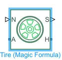
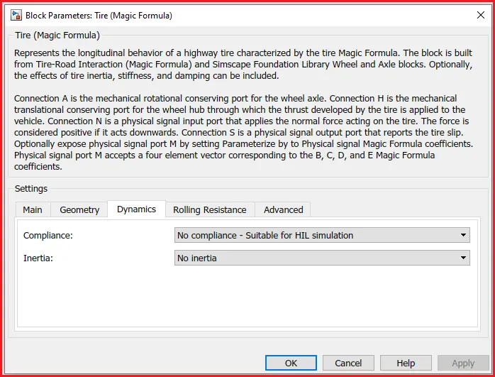
The tire represents the longitudinal behavior of a highway tire characterized by the tire Magic Formula. The block is built from Tire-Road Interaction (Magic Formula) and Simscape Foundation Library Wheel and Axle blocks. Optionally, the effects of tire inertia, stiffness, and damping can be included.
A is the mechanical rotational conserving port for the wheel axle.
H is the mechanical translational conserving port for the wheel hub through which the thrust developed by the tire is applied to the vehicle.
N is a physical signal input port that applies the normal force acting on the tire.
S is a physical signal output port that reports the tire slip.
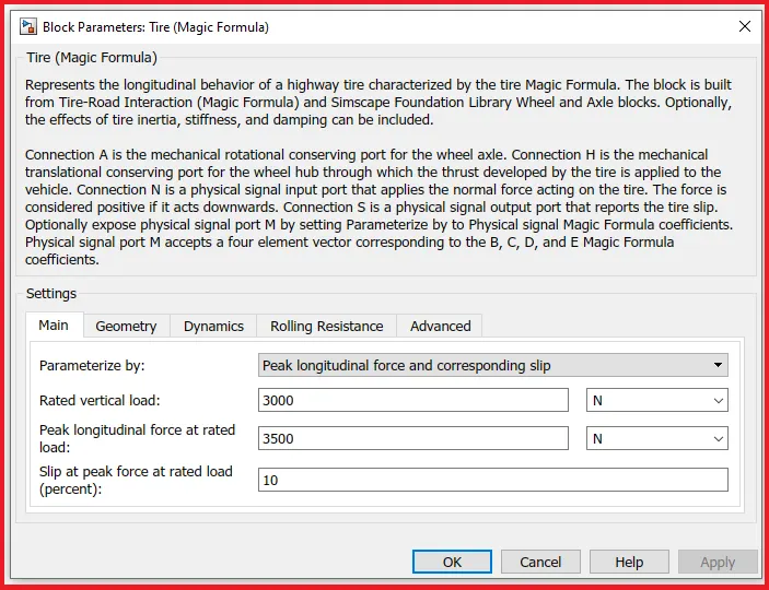
The values given for the parameters are shown below:
Vehicle Body:
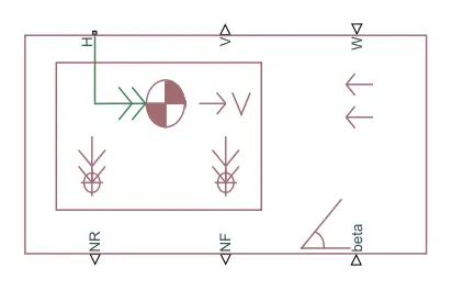
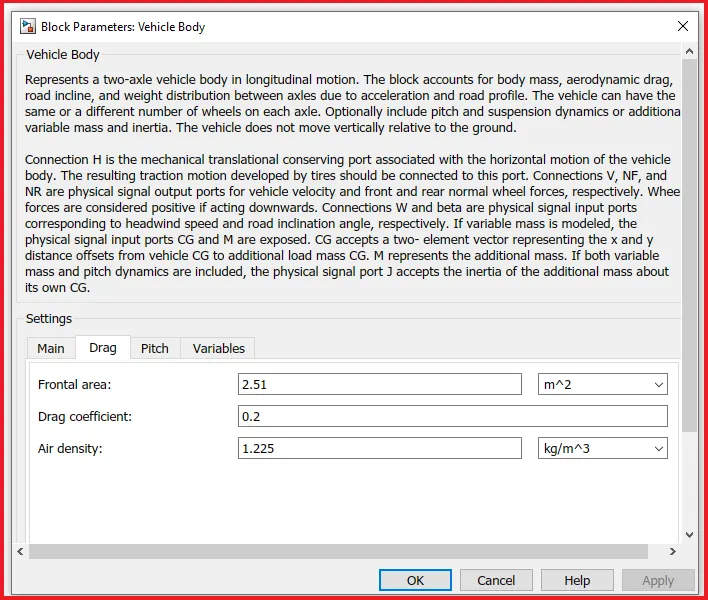
The vehicle body block represents a two-axle vehicle body in longitudinal motion. The block accounts for body mass, aerodynamic drag, road incline, and weight distribution between axles due to acceleration and road profile. The vehicle can have the same or a different number of wheels on each axle.
H is the mechanical translational conserving port associated with the horizontal motion of the vehicle body.
V, NF, and NR are physical signal output ports for vehicle velocity and front and rear normal wheel forces, respectively.
W and beta are physical signal input ports corresponding to headwind speed and road inclination angle, respectively.
The velocity of the vehicle is taken out from the 'V' port and gradeability is given through the 'beta' port and the beta port is connected with PS constant block where we can change the values.
Wind Velocity is given through the 'W' port and it is also connected with the PS constant block. the values assigned for the parameters are shown below:
The Velocity of a vehicle is given as an input for calculating the distance.
2). Permanent Magnet DC Motor:
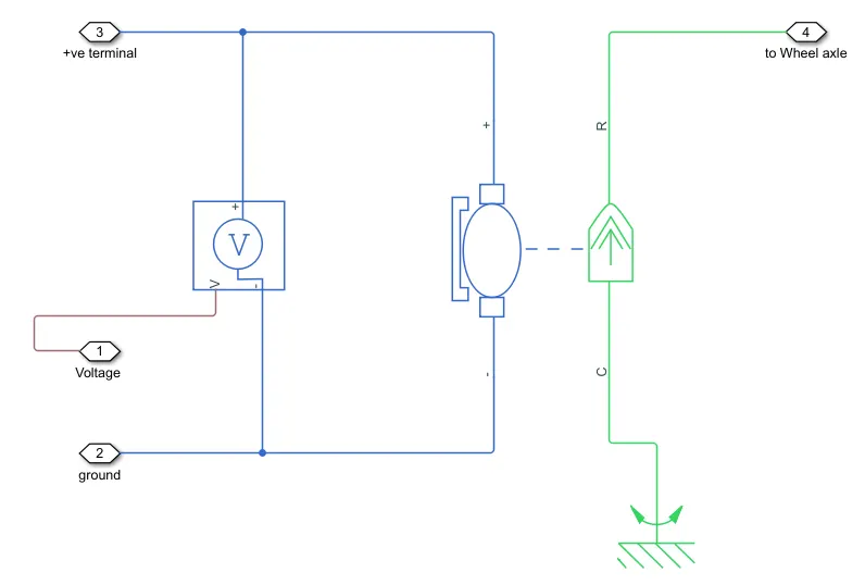
This block represents the electrical and torque characteristics of a DC motor. Here, the current from the battery flows through the positive terminal of the motor to the negative terminal, a torque acts from mechanical C to R ports. The voltage sensor is connected parallel to the DC motor.
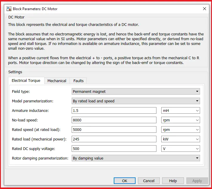
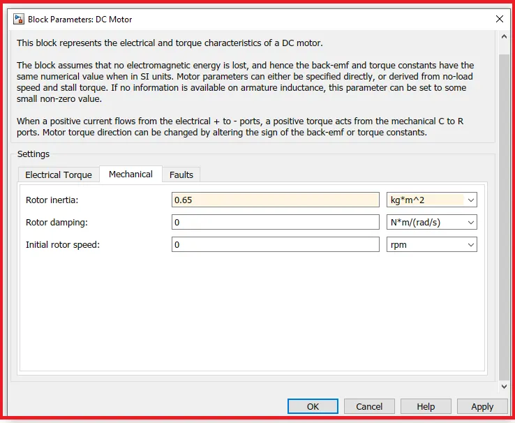
The above picture shows the parameter values we have given for the DC motor,
The motor rated voltage is 500 V DC supply
The motor rated mechanical power is 245 kW
No-load speed is 8000 rpm
The rated load speed is 5000 rpm
Armature Inductance is 1.5 mH
Rotor Inertia is 0.65 `kg.m^2`
The C port is connected with a mechanical rotational reference and the R port is connected with the simple gear transmission block of the vehicle body subsystem.
3). Power Converter:
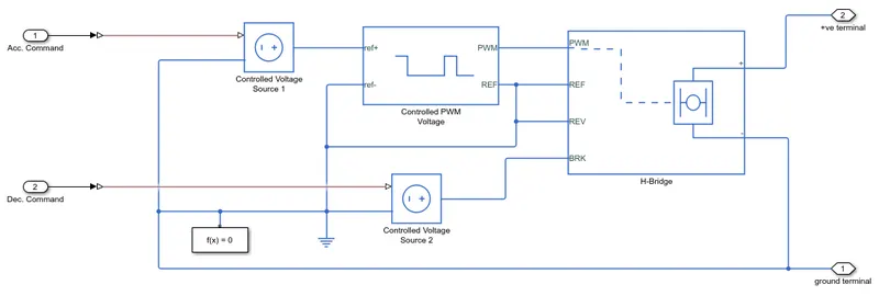
In this block, the acceleration and deceleration commands are given to both controlled voltage sources from the driver controller. The controlled voltage from the acceleration command is given as the reference voltage to the controlled PWM voltage.
Controlled Voltage Source:
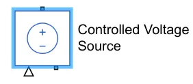
The block represents an ideal voltage source that is powerful enough to maintain the specified voltage at its output regardless of the current passing through it. The output voltage is V = Vs, where Vs is the numerical value presented at the physical signal port.
Here the acceleration and deceleration commands are given to both controlled voltage sources from the driver controller.
Controlled PWM Voltage:
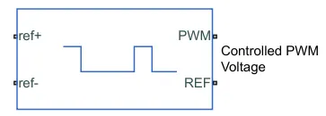
This block creates a Pulse-Width Modulated voltage across the PWM and REF ports. when the pulse is high, the output voltage is equal to the amplitude parameter and the pulse is low when the output voltage is zero.
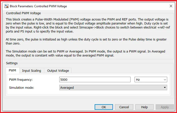
At the time zero, the pulse is initialized as high. Unless the duty cycle is set to zero or the pulse delay time is greater than zero. The simulation mode can be set to PWM or Averaged. In PWM mode the output will be a PWM signal and In the average mode, the output is constant with a value equal to the averaged PWM signal. Here I am using averaged simulation mode for the operation.
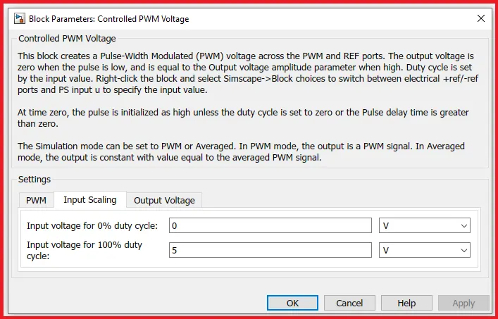
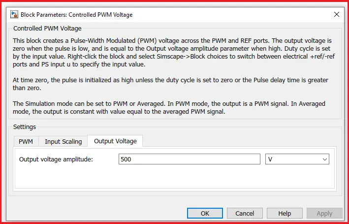
The reference voltage of controlled PWM voltage is connected with REV terminal of H-Bridge for regenerative braking and the brake input of H-Bridge is connected with the controlled PWM voltage which receives the deceleration command.
H-Bridge:
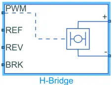
This block can be driven by the Controlled PWM Voltage in PWM or Average mode. Here we are using the internal power supply and the simulation mode in averaged mode otherwise the simulation takes more time. The regenerative braking is enabled here and the output voltage amplitude is given as 500V.
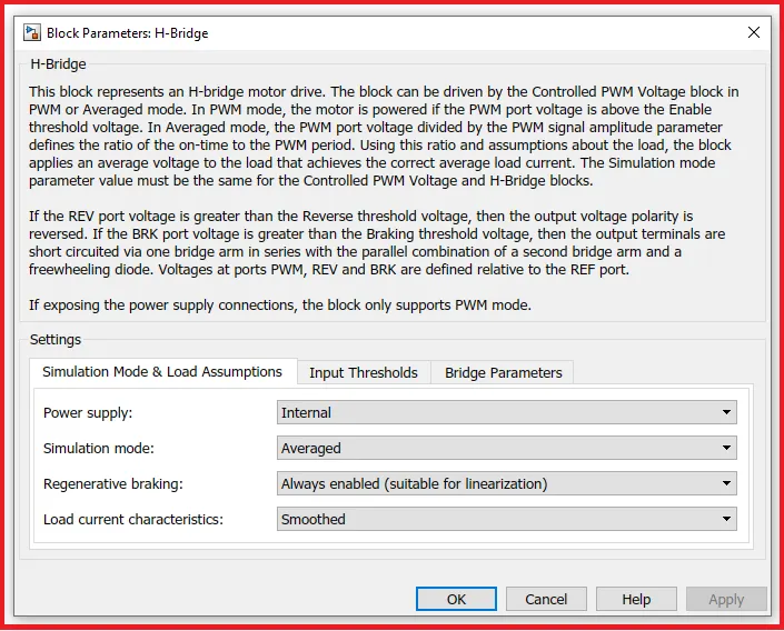
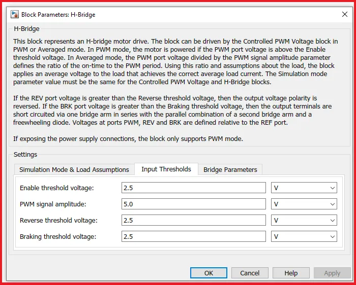
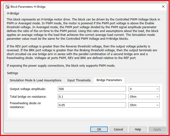
The positive terminal of the H-Bridge is connected with a positive terminal port and the negative terminal of the H-Bridge is connected with a Ground terminal port.
From the power converter block, the positive terminal is connected with the positive terminal of the battery subsystem block and the ground is connected with the ground terminal of the DC motor subsystem block.
4). Driver Controller:
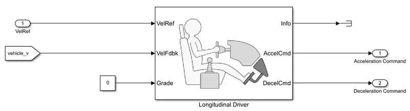
A parametric longitudinal speed tracking controller for both generating normalized acceleration and braking commands is based on velocity reference and velocity feedback. Here the terminator block is used to terminate the output signals for preventing the model from warning of unconnected output ports.
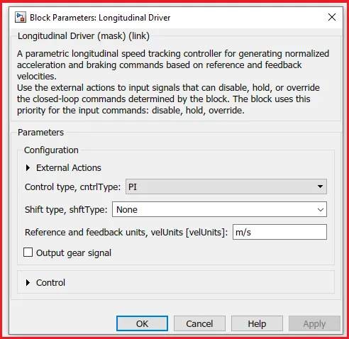
The driver gives the acceleration and deceleration commands according to the drive cycle data and it gives the acceleration and deceleration commands to the power converter block. Here we are obtaining gradeability through the constant block.
5). Drive Cycle:
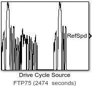
The drive cycle source block is used as an input for the Simulink model. Here, I am choosing 'FTP75' as a predefined drive cycle with a duration of 2474 seconds.
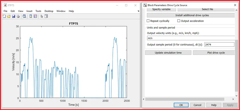
The above plot diagram shows the predefined input values of an 'FTP75' drive cycle block. The reference speed of the input block is connected with the drive controller and the output values of the drive cycle are expressed through the scope.
6). Battery System:
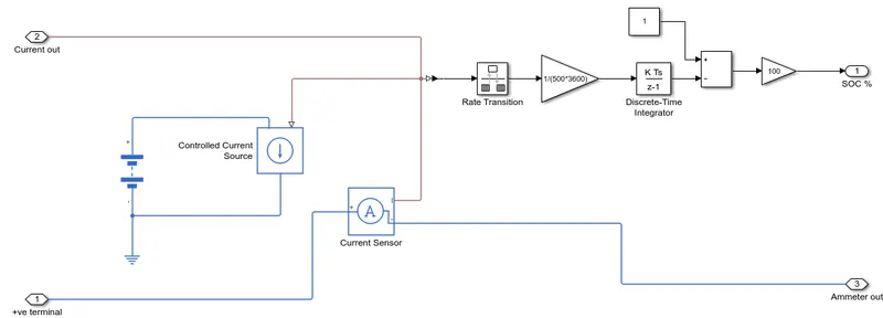
The battery source block is connected with a controlled current source through which rate transition block, gain blocks, and discrete-time integrator blocks are used for getting SOC outport.
Battery:
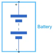
This block models a battery. If you select Infinite for the Battery charge capacity parameter, the block models the battery as a series of internal resistance and a constant voltage source. If we select Finite for the Battery charge capacity parameter, the block models the battery as a series of internal resistance plus a charge-dependent voltage source defined by:
V = Vnom*SOC/(1-beta*(1-SOC))
where SOC is the state of charge and Vnom is the nominal voltage. Coefficient beta is calculated to satisfy a user-defined data point [AH1, V1].
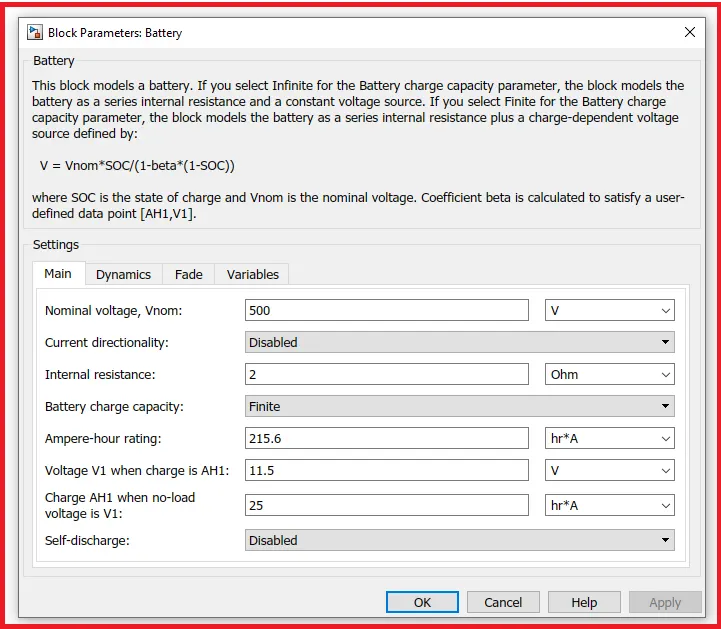
Here I am using 500v, 215.6Ah battery for the model because the vehicle accelerates, the battery gets discharged and gets charged through the regenerative braking operation. The battery is connected with a controlled current source through which the supply is passed on to the rate transition block.
Rate Transition:
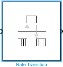
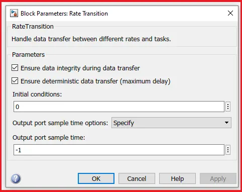
The rate transition block is used to transfer the data between different rates and tasks. This block is connected with the gain block of (1/(500*3600)) and gain values are applied to the discrete integrator.
Discrete Integrator:
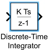
This block is used for discrete time integration or accumulation of the input signal. This block outputs the amount of charge used by the battery.
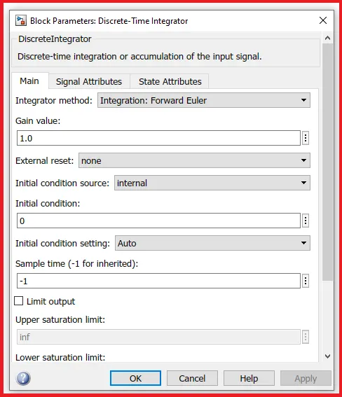
The subtracter block is used here to subtract the value from the gain block with the constant value 1 and the output value of those blocks is multiplied with a gain value of 100. Then the gain block outputs the state of charge in %. The output port of the current sensor is connected with the positive terminal of the DC motor.
7). Distance Calculation:
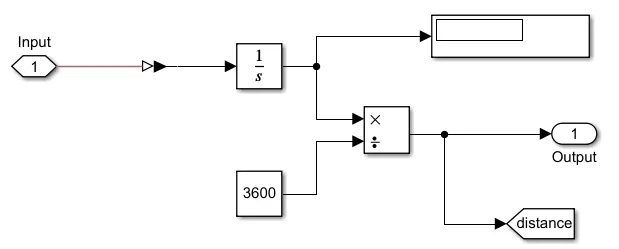
The total distance traveled is calculated by taking velocity as input and the input value is integrated through the integrator block. To get the output in kilometres, we are dividing the value from the integrator block with a constant value of 3600.
8). Energy Calculation:
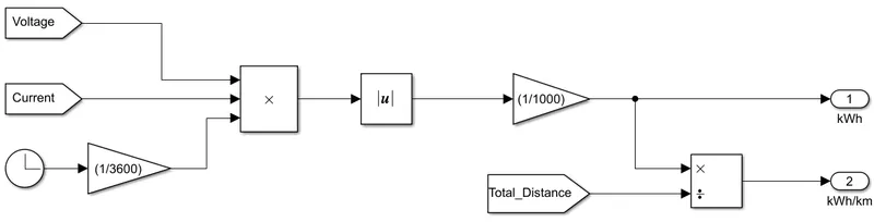
Energy= Voltage*current*time
Energy consumed per kilometer is calculated by dividing the energy by the total distance covered.
Results:
1. Drive Cycle Plot:
- By running the Vehicle with FTP75 Drive cycle for 2474 sec. the distance traveled is 5.523 km.
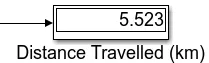
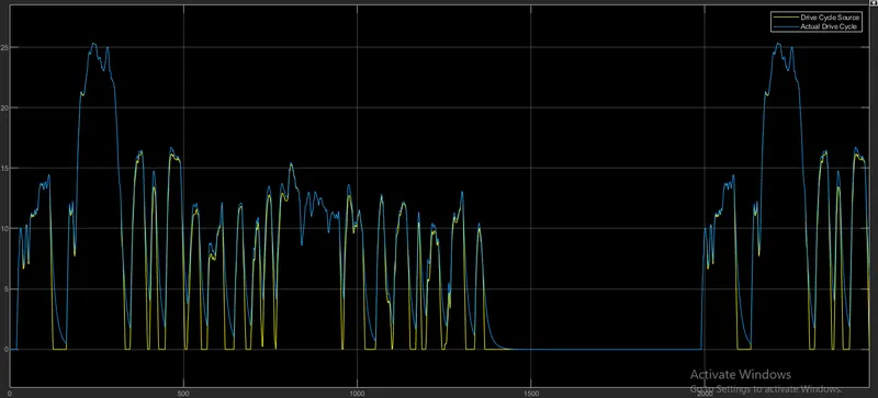
The above graphical representation represents the value of the drive cycle of both the command drive cycle and the actual drive cycle. The increase in velocity represents the acceleration and the decrease in velocity represents the deceleration.
2. Current Plot:
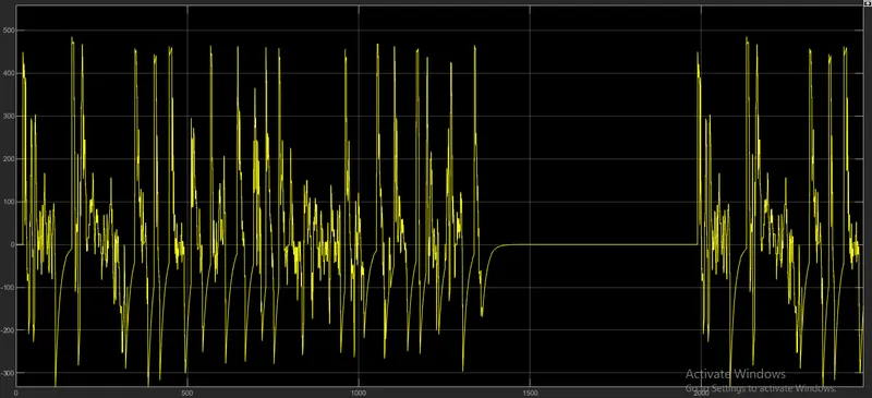
The current is increasing in the case of vehicle acceleration and decreasing in the case of regenerative braking. At last the current goes to the negative state in the case of the battery gets charging.
3. SOC Plot:
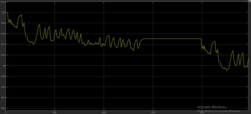
The state of charge is used for measuring the remaining charge left in the battery. At the initial stage, SOC is at 100%, when the vehicle starts accelerating, the current gets dropped and the battery starts discharging. When the vehicle starts decelerating, SOC gets increasing due to regenerative braking and the battery starts charging. SOC remains constant, at the stage of no acceleration or no braking. Here, The SoC% of the battery is reduced to only `~~99.14%`.
4. Voltage Plot:
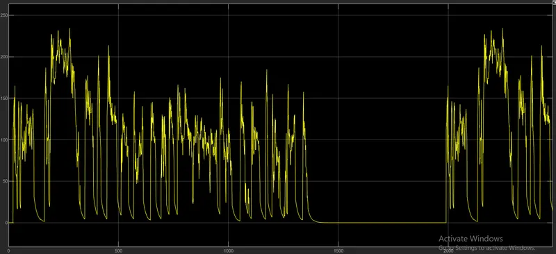
The voltage gets varies according to the drive cycle. The voltage increases when the velocity is high and the voltage gets decreases according to it.
Conclusion:
- We have designed the Matlab model of an electric vehicle by using a battery and a DC motor.
- We have done the simulation of the Electric Vehicle Model and also results are plotted and verified using the scope block.
- The output of the voltage, current, and state of charge is executed.
References:
- https://www.evspecifications.com/en/model/84bd152
- https://tech.hyundaimotorgroup.com/article/ev-a-to-z-encyclopedia-1-understanding-ev-components/
- https://evcharging.enelx.com/resources/blog/566-different-types-of-electric-vehicles
- https://en.wikipedia.org/wiki/Plug-in_hybrid
- https://downloads.ctfassets.net/qp8rp917jhxs/4IcWlXFZvGeeocKqEw0q44/94ec2806287f8753a7c0938635954930/LSK_DC_motors_Leroy-Somer__2_.pdf