Final Project: Design of an Electric Vehicle
Note- This is Live EV Batch-21.
Electric Car-
An electric car (battery electric car, or all-electric car) is an automobile that is propelled by one or more electric motors, using only energy stored in battries. Compared to internal combustion engine (ICE) vehicles, electric cars are quieter, have no exhaust emission, and lower emission overall.Electric cars function by plugging into a charge point and taking electricity from the grid.The stored electricity in batteries is used during propultion.
Components-
Electric Motor-
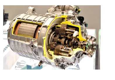
An electric motor is an electrical machine that converts electrical energy into mechanical energy. Most electric motors operate through the interaction between the motor's magnetic field and electric current in a wire winding to generate force in the form of torque applied on the motor's shaft. An electric genrator is mechanically identical to an electric motor, but operates with a reversed flow of power, converting mechanical energy into electrical energy.
Electric motors can be powered by direct current (DC) sources, such as from batteries, or rectifiers, or by AC sources, such as a power grid, inverters or electrical generators.
Battery Management System-
The BMS manages the electrical current flow in and out of the battery to protect the battery and extend the life.It monitors the battery pack’s state of charge (SOC) along with the state of health (SOH).
This requires Battery Management System (BMS), an embedded system,which monitors the components closer to the battery cell, as each cell needs to be closely monitored so that there are no voltage fluctuations or imbalance in voltage conditions. The BMS consists of different components that ensure that the battery runs efficiently without chances of possible failures.
H-Bridge-
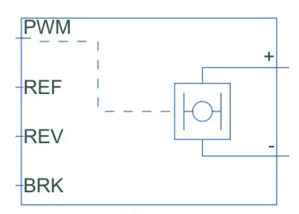
The H-bridge helps in controlling the power that is input according to the requirments.The output provided are converted voltage as per the controlled parameter.
DC Motor-
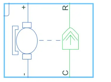
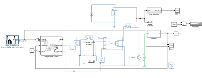
This is the DC motor which gives the rotational power to wheel.From '+' terminal ,the positive supply is given to motor and from '-' terminal ,negative supply provided to motor.
'R'-from here connect the rotational wheel.
'C'- This is used for rotational mechanical reference.
Controlled PWM Voltage-
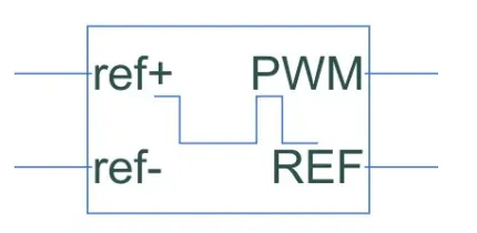
This blocks helps in keeping the modulated pulse as per required pulses.So that the operation happens in smooth manner and higher variation are not observed.
The port are used as-
ref+ =Positive reference are connected with acceleration commands from Driver model.
ref- =Negative reference are connected with Deceleration commands from Driver model.
PWM=PWM is directly connected to the H block.
REF=REF is directly connected to the H block.
Driver Model-
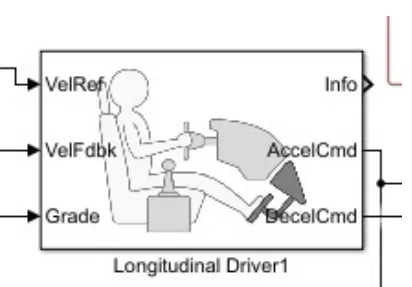
The Longitudinal Driver block implements a longitudinal speed-tracking controller. Based on reference and feedback velocities, the block generates normalized acceleration and braking commands according to of drive cycle. You can use the block to model the dynamic response of a driver or to generate the commands necessary to track a longitudinal drive cycle.
Drive cycle-
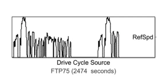
This drive cycle block has four different cycle source as give below image-
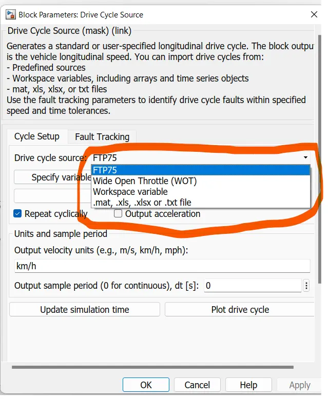
As in the simulation we are using FTTP75 cycle.
Vehicle Body-
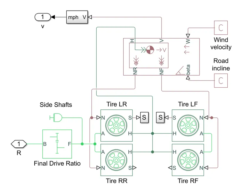
As there are many factor used in vehicle body as Tyre,Drive Ratio,Side saft,Wind velocityAnd road incline fator.
Tire-
The Tire (Magic Formula) block models a tire with longitudinal behavior given by the Magic Formula [1], an empirical equation based on four fitting coefficients. The block can model tire dynamics under constant or variable pavement conditions.
The longitudinal direction of the tire is the same as its direction of motion as it rolls on pavement. This block is a structural component based on the tire road interaction block.
To increase the fidelity of the tire model, you can specify properties such as tire compliance, inertia, and rolling resistance. However, these properties increase the complexity of the tire model and can slow down simulation. Consider ignoring tire compliance and inertia if simulating the model in real time or if preparing the model for hardware-in-the-loop (HIL) simulation.
Gear Ratio-
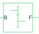
The Simple Gear block represents a gearbox that constrains the connected driveline axes of the base gear, B, and the follower gear, F, to corotate with a fixed ratio that you specify. You choose whether the follower axis rotates in the same or opposite direction as the base axis. If they rotate in the same direction, the angular velocity of the follower, ωF, and the angular velocity of the base, ωB, have the same sign. If they rotate in opposite directions, ωF and ωB have opposite signs. You can easily add and remove backlash, faults, and thermal effects.
Battery-
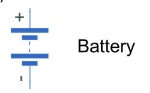
The battery is connected to fulfill the power requirement.
Simulink block of system-
OUTPUT-
Actual speed v/s reference speed-
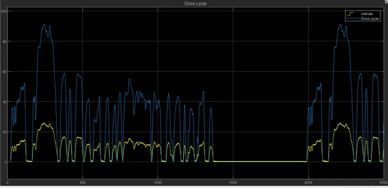
- As from above graph ,we can see that the actual velocity of the vehicle is differ from the reference drive cycle velocity.
- This is because the battery capacity and motor speed are not able to meet the required refernce velocity.
Battery SOC-
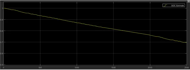
- As we can see that the battery is going discharge and at the end of simulation ,it is nearly about 70%.
- So the battery is not completly drained at the end and it can run more distance
Distance-
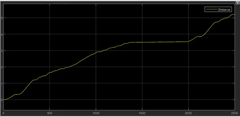
The total distance covered 5.3km.
Conclusion-
The model run successfully for simulation under the standard FTP75 drive cycle.The result have been analyzed as Battery SOC ,Distance,Real time simulation properly.