Final Project: Design of an Electric Vehicle
ANSWER
Electric car:
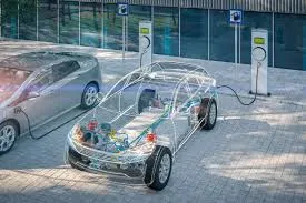
All-electric vehicles (commonly referred to as EVs or BEVs) don’t use gasoline and instead have a large battery that powers one or more electric motors. Currently, all-electric vehicles have a driving range of 80 to more than 300 miles, with ranges increasing as new models are introduced. In addition to driving past the gas station, all-electric vehicles don’t require much maintenance (such as oil changes, smog checks, spark plug changes, replacing a catalytic converter, or other parts that wear out and break down) compared to gas cars. All-electric vehicles can be charged at home using standard 120-volt or 240-volt house plugs, or away from home at public or workplace charging stations. One benefit of all-electric vehicles over plug-in hybrids is the capability to use dc fast chargers, which provide more than 100 miles of range in 30 minutes.
Plug-In Hybrid Electric Vehicles:
Plug-in hybrid electric vehicles (commonly referred to as PHEVs) offer both gas-only and electric-only driving—even at relatively high speeds. With smaller batteries than battery electrics, plug-in hybrids achieve an electric-only range of 20-55 miles, during which they produce no tailpipe emissions. When the car uses up its electric range, it switches to gas and drives just like a conventional car.
Fuel cell electric vehicles:
Fuel cell electric vehicles (commonly referred to as FCEVs) run on electricity but do so differently than all-electric vehicles or plug-in hybrids. Its power system comprises numerous cells combined into a stack that chemically combines hydrogen gas from the car’s tank and oxygen from the air to produce electricity. Fuel cells have a driving range of 300-400 miles on a single tank and can be refueled in about five minutes at hydrogen fueling stations, becoming more common in California. They also have all of the perks of an electric vehicle, including a smooth, quiet ride, and incentives and are eligible for the carpool lane decal to help you hop in the carpool lane. An additional benefit for fuel cell drivers is that auto manufacturers provide three years’ worth of free hydrogen fuel.
COMPONENTS OF ELECTRIC CAR
- battery with BMS controller
- inverter and converter
- motor or generator
- charger
- storage device
BATTERY:
A battery is a device that converts chemical energy contained within its active materials directly into electric energy using an electrochemical oxidation-reduction (redox) reaction. This type of reaction involves the transfer of electrons from one material to another via an electric circuit. While the term battery is often used the cell is the actual electrochemical unit used to generate or store electric energy. In understanding the differences between a cell and a battery, one should think of a battery as one or more of these cells connected in series, parallel, or both, depending on the desired output voltage and capacity.
All the electrochemical cells and batteries are classified into two types:
- Primary (non-rechargeable)
- Secondary (rechargeable)
Even though there are several other classifications for these two types of batteries, these two are the basic types. Simply speaking, Primary Batteries are non-rechargeable batteries i.e., they cannot be recharged electrically while Secondary Batteries are rechargeable batteries i.e., they can be recharged electrically.
Primary batteries:
A Primary Battery is one of the simple and convenient sources of power for several portable electronic and electrical devices like lights, cameras, watches, toys, radios, etc. As they cannot be recharged electrically, they are of the “use it and when discharged, discard it” type. Usually, primary batteries are inexpensive, lightweight, small, and very convenient to use with relatively no or less maintenance. The majority of the primary batteries that are used in domestic applications are single cell types and usually come in cylindrical configurations (although, it is very easy to produce them in different shapes and sizes).
The most significant development in battery technology took place during the 1970 – 1990 period. It is during this time, that the famous Zinc / Alkaline Manganese Dioxide batteries were developed and they slowly replaced the older Zinc – Carbon types as the main primary battery.
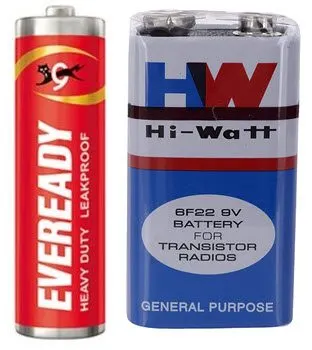
The following table shows different types of primary batteries along with their characteristics and applications.
| Battery Type | Characteristics | Applications |
| Zinc – Carbon | Common, low cost, variety of sizes | Radios, toys, instruments |
| Magnesium (Mg/MnO2) | High capacity, long shelf life | Military and aircraft Radios |
| Mercury (Zn/HgO) | Very high capacity, long shelf life | Medical (hearing aids, pacemakers), photography |
| Alkaline (Zn/Alkaline/MnO2) | Very popular, moderate cost, high performance | Most popular primary batteries |
| Silver/Zinc (Zn/Ag2O) | Highest capacity, costly, flat discharge | Hearing aids, photography, pagers |
| Lithium/Soluble Cathode | High energy density, good performance, wide temp range | Wide range of applications with a capacity between 1 – 10,000 Ah |
| Lithium/Solid Cathode | High energy density, low temp performance, long shelf life | Replacement for button and cylindrical cells |
| Lithium/Solid Electrolyte | Low power, extremely long shelf life | Memory circuits, medical electronics |
Secondary batteries:
A Secondary Battery is also called a Rechargeable Battery as it can be electrically recharged after discharge. The chemical status of the electrochemical cells can be “recharged” to their original status by passing a current through the cells in the opposite direction of their discharge.
Secondary batteries can be used in two ways:
- In the first category of applications, the secondary batteries are essentially used as energy storage devices where they are electrically connected to the main energy source and also charged by it and also supply energy when required. Examples of such applications are Hybrid Electric Vehicles (HEV), Uninterrupted Power Supplies (UPS), etc.
- The second category of applications of secondary batteries is those applications where the battery is used and discharged as a primary battery. Once it is completely discharged (or almost completely discharged), instead of discarding it, the battery is recharged with an appropriate charging mechanism. Examples of such applications are all the modern portable electronics like mobiles, laptops, electric vehicles, etc.
There are some other types of Secondary Batteries but the four major types are:
- Lead – Acid Batteries
- Nickel – Cadmium Batteries
- Nickel–Metal Hydride Batteries
- Lithium-Ion Batteries
INVERTER AND CONVERTER
An inverter is one of the most important pieces of equipment in a solar energy system. It's a device that converts direct current (DC) electricity, which is what a solar panel generates, to alternating current (AC) electricity, which the electrical grid uses. The inverter may be built as standalone equipment for applications such as solar power, or to work as a backup power supply from batteries that are charged separately.
The other configuration is when it is a part of a bigger circuit such as a power supply unit, or a UPS. In this case, the inverter input DC is from the rectified mains AC in the PSU, while from either the rectified AC in the UPS when there is power, or from the batteries whenever there is a power failure. There are different types of inverters based on the shape of the switching waveform. These have varying circuit configurations, efficiencies, advantages, and disadvantages.
An inverter provides an ac voltage from dc power sources and is useful in power electronics and electrical equipment rated at the ac mains voltage. In addition, they are widely used in the switched-mode power supply inverting stages. The circuits are classified according to the switching technology and switch type, the waveform, the frequency, and the output waveform.
BASIC INVERTER OPERATION
The basic circuits include an oscillator, control circuit, drive circuit for the power devices, switching devices, and a transformer.
The conversion of dc to alternating voltage is achieved by converting energy stored in the dc source such as the battery, or from a rectifier output, into an alternating voltage. This is done using switching devices that are continuously turned on and off, and then stepping up using the transformer. Although some configurations do not use a transformer, these are not widely used.
The DC input voltage is switched on and off by the power devices such as MOSFETs or power transistors and the pulses are fed to the primary side of the transformer. The varying voltage in the primary induces an alternating voltage at the secondary winding. The transformer also works as an amplifier where it increases the output voltage at a ratio determined by the turn’s ratio. In most cases, the output voltage is raised from the standard 12 volts supplied by the batteries to either 120 Volts or 240 volts AC.
The three commonly used Inverter output stages are, a push-pull with center tap transformer, push-pull half-bridge, or push-pull full bridge. The push-pull with center tap is most popular due to its simplicity and, guaranteed results; however, it uses a heavier transformer and has lower efficiency.
A simple push-pull DC to AC inverter with a center tap transformer circuit is shown in the figure below.
Figure 1 basic inverter switching circuit
converter:
A converter is an electrical circuit that accepts a DC input and generates a DC output of a different voltage, usually achieved by high frequency switching action employing inductive and capacitive filter elements. A power converter is an electrical circuit that changes the electric energy from one form into the desired form optimized for the specific load. A converter may do one or more functions and give an output that differs from the input. It is used to increase or decrease the magnitude of the input voltage, invert polarity, or produce several output voltages of either the same polarity with the input, different polarity, or mixed polarities such as in the computer power supply unit. The DC to DC converters is used in a wide range of applications including computer power supplies, board-level power conversion and regulation, dc motor control circuits, and much more.
The converter acts as the link or the transforming stage between the power source and the power supply output. There are several kings of converters based on the source input voltage and the output voltage and these fall into four categories namely the AC to DC converter known as the rectifier, the AC to AC cyclo converter or frequency changer, the DC to DC voltage or current converter, and the DC to AC inverter.
The converter uses nonlinear components such as the semiconductor switches, and linear reactive components such as the inductors, transformers, and capacitors for intermediate energy storage as well as current and voltage filtering. The size, weight, and cost of the converter are largely determined by these components. There three basic converter circuits that are widely used in DC to DC converters are the buck, boost, and the buck and boost. These configurations are the most used topologies due to their simplicity and use of fewer components. Each has its advantages and drawbacks which determines the suitability for any specific application.
The buck converter is a step-down, the boost a step-up while the buck-boost is both step-up and step-down. All these are non-isolated and use the inductor as the energy transfer element and are mostly used in board-level power conversion and regulation. The isolated dc to dc converters use a transformer to provide the isolation, multiple outputs, a different voltage level, or polarity depending on the turn ratios and directions of the windings.
fig. full-bridge DC converter
Converters are widely used in electronic equipment, power supplies, and other circuits requiring specific voltage and current levels other than the available raw supply energy. The converters provide any type of the required voltage at the desired magnitude. With a proper design and use of the almost ideal components, the available methods of conversion offer a variety of reliable and efficient energy to power most electronic devices and components.
The word "motor" refers to any power unit that generates motion, that is a "prime mover", while "electric motor" refers to a "prime mover using electricity."
An electric motor is a device used to convert electrical energy into mechanical energy.
Scientifically speaking, the electric motor is a unit used to convert electric power into motive energy or electrical energy into mechanical energy. Fig. 1.1 is a flow diagram of energy. The left end of the arrow represents the electrical input and the right end the mechanical output respectively. Electrical input may be simply shortened to read input, and mechanical output (motive energy) can be simply shortened to output.
Some input becomes heat instead of motive energy during the energy conversion process. This is called loss. In Japan, over 60% of total power generated is used with motors. In terms of conserving the environment, the design and use of motors with less loss is an important challenge. The following relationship exists among the above-mentioned input power, output (also called motive energy), and loss:
Input power = mechanical output + loss
The unit for those amounts is Watt [W].
Input power and mechanical output are defined by the following equations:
Input power [W] = Voltage [V] x Current [A]
Mechanical output [W] = Rotating speed [rad/s] x Rotative force [Nm]
(rad is called radian and Nm Newton meter)
Motor efficiency refers to the fraction of mechanical output to input power as a percentage (%).
Loss includes (for example) loss caused by mechanical phenomena such as friction, but it typically consists of loss in the copper wire and the core. The former is called copper loss and the latter iron loss
GENERATOR
An electric generator also called a dynamo, is any machine that converts mechanical energy to electricity for transmission and distribution over power lines to domestic, commercial, and industrial customers. Generators also produce the electrical power required for automobiles, aircraft, ships, and trains.
The mechanical power for an electric generator is usually obtained from a rotating shaft and is equal to the shaft torque multiplied by the rotational, or angular, velocity. The mechanical power may come from several sources: hydraulic turbines at dams or waterfalls; wind turbines; steam turbines using steam produced with heat from the combustion of fossil fuels or nuclear fission; gas turbines burning gas directly in the turbine; or gasoline and diesel engines. The construction and the speed of the generator may vary considerably depending on the characteristics of the mechanical prime mover.
Nearly all generators used to supply electric power networks generate alternating current, which reverses polarity at a fixed frequency (usually 50 or 60 cycles, or double reversals, per second). Since several generators are connected to a power network, they must operate at the same frequency for a simultaneous generation. They are therefore known as synchronous generators or, in some contexts, alternators.
CHARGER
Its main job is to recharge the battery of an EV to keep the vehicle in motion. Most eclectic vehicles' batteries can only be charged with direct current (DC) power, yet some EV have a charger that converts alternating current (AC) electricity into DC and then sends this power to the vehicle's charging port.
One of the biggest concerns for electric vehicle (EV) owners is knowing when and how to charge their vehicles. Both electric vehicles and plug-in hybrid electric vehicles require an EV charger to keep the battery full, just like any chargeable device or electronic. At its most basic, an EV charger pulls an electrical current from either a 240v outlet or the grid it’s hardwired to and delivers that electricity to the vehicle, just like any other appliance or device you charge by plugging into the wall.
STORAGE DEVICE
The energy storage device (ESD) is used in a power system network to store the surplus energy during the off-peak period and utilize the stored energy during the peak period. It is installed at strategic locations to improve the power system performance and meet the peak demand.
Electricity is more than just another means of powering the vehicle. The EV requires an energy storing system which is one of the concerns of today's EV technology. Batteries are the energy storage means for EVs. Specific energy and specific power of electrochemical batteries are generally much smaller than those of gasoline.
SIMULATION OF ELECTRIC CAR
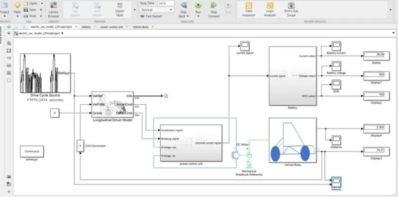
This is the block diagram of the electric car components and machines.
now let us see each block in detail
DRIVE CYCLE SOURCE:
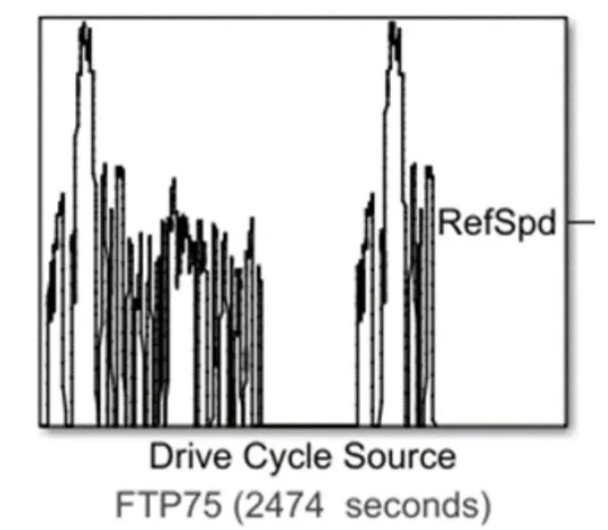
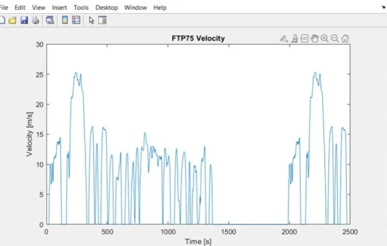
This block is located in the Simulink library at the powertrain block set. It is like input data or a reference value block which is used as an import to the blocks for the standard signals for the input connection. Here we have used the drive cycle FTP 75 with 2474 sec data.
the parameters are as follows
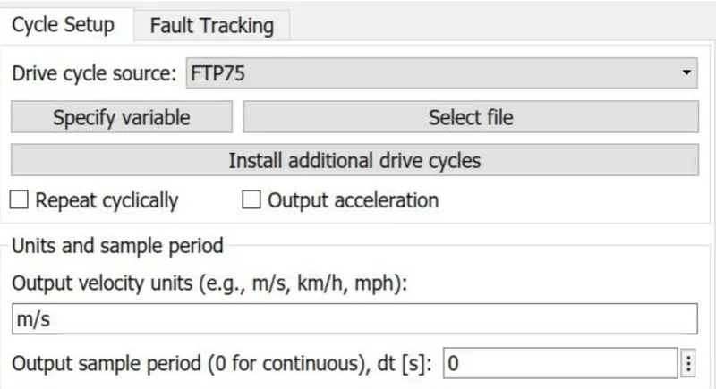
Here we can use the data as required by changing the settings in the drive cycle source from the FTP 75 to WOT or another that we need.
THE CHARACTERISTICS OF THE GIVEN DRIVE CYCLE ARE AS FOLLOWS:
LONGITUDINAL DRIVER MODEL:
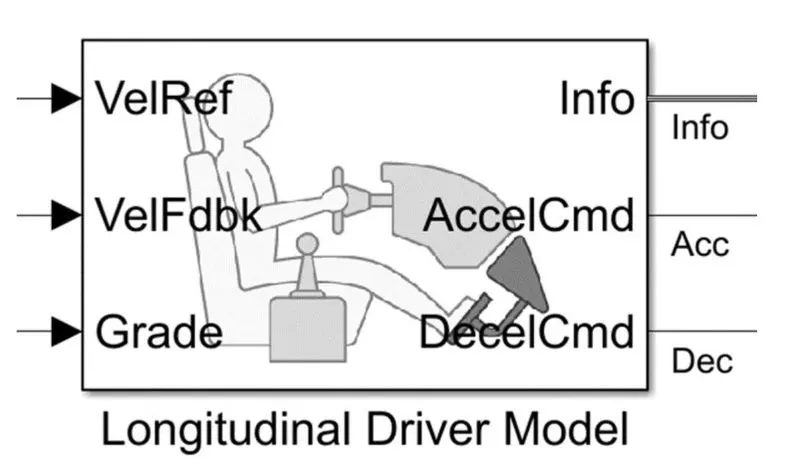
This model block is also located in the power train block set. It is like a driver which is used to take charge of driving its acceleration breaking commands as per the given conditions called a reference. It is also called an auto control as it takes the feedback from the vehicle and runs it as per the given values and changes its commands based on the feet back with the reference values respectively.
This block is used to create a longitudinal speed tracking controller and is based on reference and feedback velocity. This block can also be used to model the dynamic response of the driver to generate the commands necessary to track a longitudinal drive cycle. The v e l is used to take the reference values for the driver to drive the vehicle. The v e l feedback is used to take the feedback from the output of the given data from the vehicle speed called velocity.
The ACCEL CMD is an output signal that gives an input to the power control unit voltage source one which is connected to the PWM for accelerating when the output is reduced to lower than the given reference value.
The DECEL CMD is also an output signal that gives an input to the power control unit voltage source which is connected to the break for breaking when the output becomes higher than the given reference value.
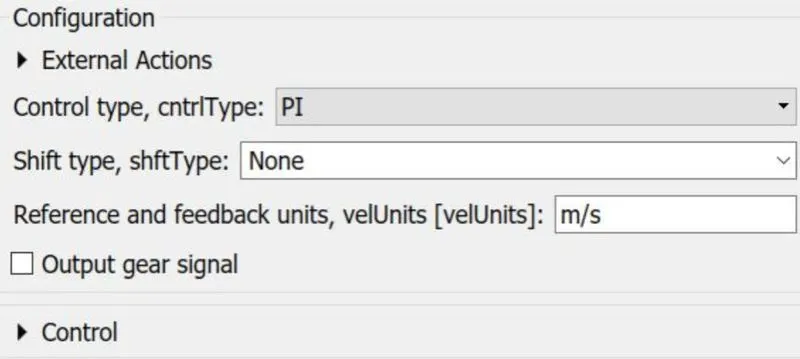
BLOCK PARAMETERS
POWER CONTROL UNIT SUBSYSTEM
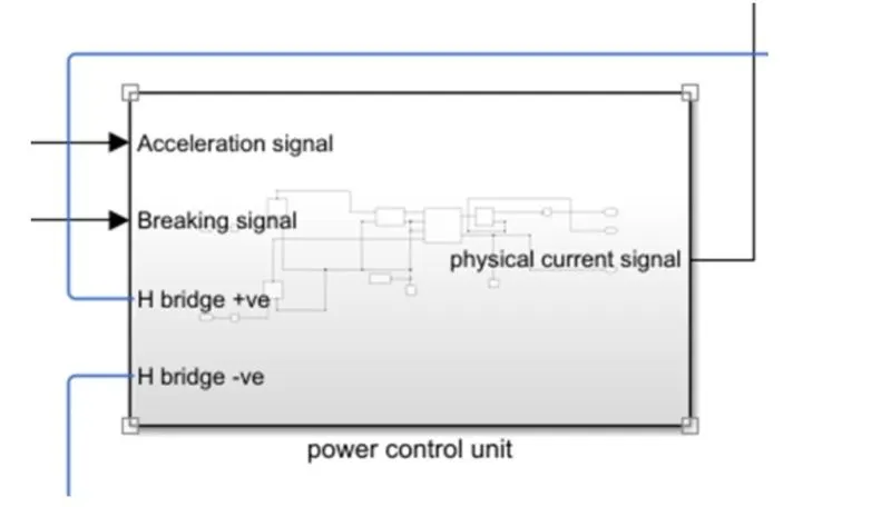
the inner system looks like this:
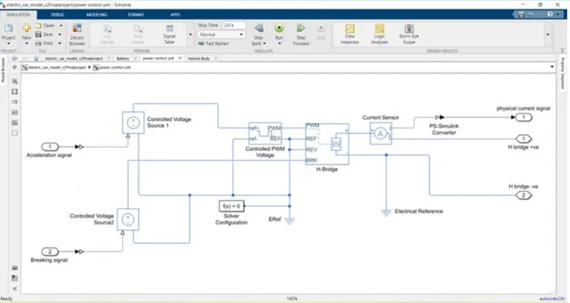
MOTOR CONTROLLER:
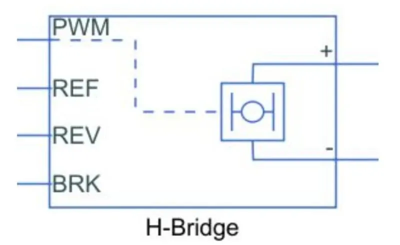
This block represents an H-bridge motor drive. This block can be driven by the control PWM voltage block in PWM or average mode.
In the PWM mode, the motor is powered if the PWM port voltage is above the enabled threshold voltage.
In average mode, the PWM port voltage divided by the PWM signal amplitude parameter defines the ratio of the on-time to the PWM period.
The connection ref is for the reference input this is combined with the PWM connected with form the pulse input for the edge bridge. Here the reference input is connected to the ground.
The connection REV corresponds to the reverse motion of the motor which essentially means the backward motion is not accounted for and shows the port is connected to the electrical reference.
The BRK connection is for breaking the vehicle.
Since the PW mode results in a huge amount of simulation time the average mode is selected for this simulation. The load current characteristics here are considered to be smooth. Also, the regenerative braking is enabled for simulation which means that when the vehicle starts decelerating the corresponding amount of charge will be fed back to the battery. Accordingly, the brake input is connected to the controlled voltage source which generates EMF corresponding to the intensity of brakes better applied and the power is fed back to the battery.
BATTERY PACK
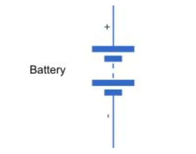
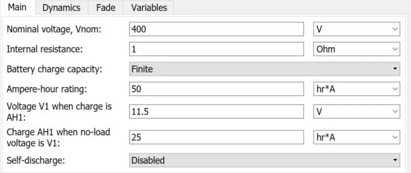
To model the battery pack, a simple battery block is used. Because the generic battery block is used instead the simulation will run for a much longer time. Here, the selected option for battery charge capacity is finite. Accordingly, the block models the battery as a series of internal resistance plus a charge-dependent voltage source. If the selected option had been infinite, the voltage source would have been constant. The battery's self-discharging and dynamics are also disabled.
The Nominal battery voltage is 400V and the ampere-hour rating is assumed to be around 50, and other parameters are default.
OUTPUTS:
1) SPEED VS ACTUAL VEHICLE SPEED:
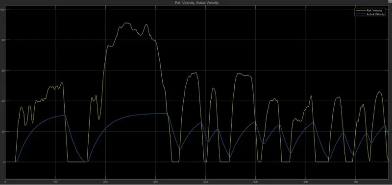
from the above output, we can see that the actual vehicle velocity differs from the reference vehicle velocity. This is because the chosen battery capacity and motor are not able to propel the speed up to the required extent.
If a battery of higher capacity is chosen, the actual velocity will tend to match the reference velocity.\
Also, it is noted that in certain regions, even when the drive cycle shows small decelerations, the vehicle actually accelerates with decreasing magnitudes due to the same reason.
2) DISTANCE COVERED:
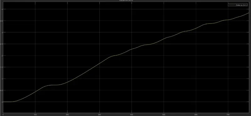
Here, as the reference velocity of the vehicle never becomes negative, the distance increases throughout. Hence the total distance covered by the vehicle is about 3.8 km.
BATTERY STATE OF CHARGE:
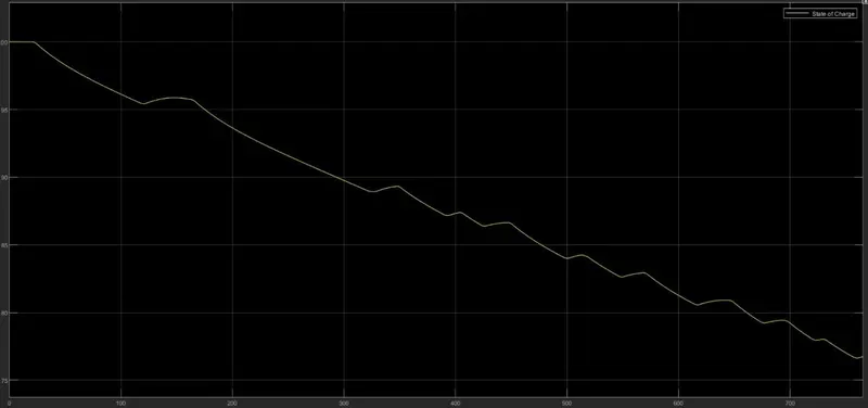
The battery SOC at the end of the simulation run is about 77%, i.e the battery is not fully drained and the vehicle can run a few more times on the same drive cycle until the SOC becomes 0.
Also, as we had enabled the regenerative braking, the battery SOC increases a little bit whenever the vehicle undergoes heavy deceleration, which depends upon the generating tendency of the motor and the maximum amount of current that the battery can take up.
CONCLUSION:
The model simulation is successfully run, and the results are analyzed.