Final Project: Design of an Electric Vehicle
Objective -
To create a MATLAB model of electric car which uses a battery and a DC motor.
Model -
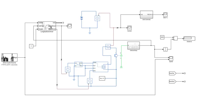
Blocks Used -
The blocks used are
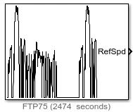
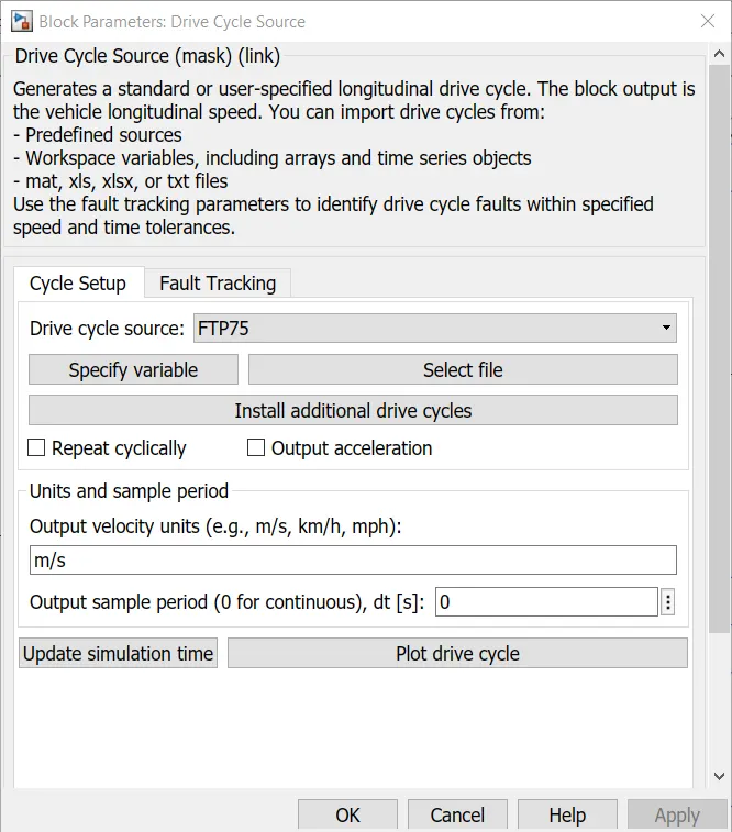
- Drive Cycle Source - The Drive Cycle Source block generates a standard or user-specified longitudinal drive cycle.
The block output is the specified vehicle longitudinal speed, which you can use to:
- Predict the engine torque and fuel consumption that a vehicle requires to achieve desired speed and acceleration for a given gear shift reference.
- Produce realistic velocity and shift references for closed loop acceleration and braking commands for vehicle control and plant models.
- Study, tune, and optimize vehicle control, system performance, and system robustness over multiple drive cycles.
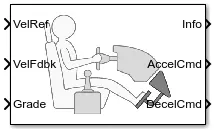
- Longitudinal Driver - The Longitudinal Driver block implements a longitudinal speed-tracking controller. Based on reference and feedback velocities, the block generates normalized acceleration and braking commands that can vary from 0 through 1. It is use to model the dynamic response of a driver or to generate the commands necessary to track a longitudinal drive cycle.
- Controlled Voltage Source - The Controlled Voltage Source block represents an ideal voltage source that is powerful enough to maintain the specified voltage at its output regardless of the current flowing through the source.
- Controlled PWM Voltage - The Controlled PWM Voltage block represents a pulse-width modulated (PWM) voltage source.
- H-Bridge - The H-Bridge block represents an H-bridge motor driver. The block has the following two Simulation mode options:
- PWM — The H-Bridge block output is a controlled voltage that depends on the input signal at the PWM port.If the input signal has a value greater than the Enable threshold voltage parameter value, the H-Bridge block output is on and has a value equal to the value of the Output voltage amplitude parameter. If it has a value less than the Enable threshold voltage parameter value, the block maintains the load circuit using one of the following three Freewheeling mode options
- Via one semiconductor switch and one freewheeling diode
- Via two freewheeling diodes
- Via two semiconductor switches and one freewheeling diode
- Averaged — This mode has two Load current characteristics options
- Smoothed
- Unsmoothed
- PWM — The H-Bridge block output is a controlled voltage that depends on the input signal at the PWM port.If the input signal has a value greater than the Enable threshold voltage parameter value, the H-Bridge block output is on and has a value equal to the value of the Output voltage amplitude parameter. If it has a value less than the Enable threshold voltage parameter value, the block maintains the load circuit using one of the following three Freewheeling mode options
- DC Motor - DC motor model with electrical and torque characteristics and fault modeling. The DC Motor block represents the electrical and torque characteristics of a DC motor using the following equivalent circuit model
- Current Sensor - The Current Sensor block represents an ideal current sensor, that is, a device that converts current measured in any electrical branch into a physical signal proportional to the current.
- Controlled Current Source - The Controlled Current Source block represents an ideal current source that is powerful enough to maintain the specified current through it regardless of the voltage across the source.
- Product - The Product block outputs the result of multiplying two inputs: two scalars, a scalar and a nonscalar, or two nonscalars that have the same dimensions.

- Constant - The Constant block generates a real or complex constant value signal. Use this block to provide a constant signal input.

- Integrator - The Integrator block outputs the value of the integral of its input signal with respect to time.

- Battery - The Battery block represents a simple battery model.
- Mechanical Rotational Reference - The Mechanical Rotational Reference block represents a reference point, or frame, for all mechanical rotational ports. All rotational ports that are rigidly clamped to the frame (ground) must be connected to a Mechanical Rotational Reference block.
- Electrical Reference - The Electrical Reference block represents an electrical ground. Electrical conserving ports of all the blocks that are directly connected to ground must be connected to an Electrical Reference block. A model with electrical elements must contain at least one Electrical Reference block.
- Scope - It display signals generated during simulation.

- Display - The Display block shows the value of the input data. You can specify the frequency of the display. For numeric input data, you can also specify the format of display.
- PS-Simulink Converters - The PS-Simulink Converter block converts a physical signal into a Simulink® output signal. Use this block to connect outputs of a Simscape™ physical network to Simulink scopes or other Simulink blocks.
- Simulink-PS Converters - The Simulink-PS Converter block converts the input Simulink® signal into a physical signal. Use this block to connect Simulink sources or other Simulink blocks to the inputs of a Simscape™ physical network.
- Solver Configuration - Each physical network represented by a connected Simscape™ block diagram requires solver settings information for simulation. The Solver Configuration block specifies the solver parameters that your model needs before you can begin simulation.
The subsystems created are
Vehicle Body subsystem - The vehicle subsystem is shown below -
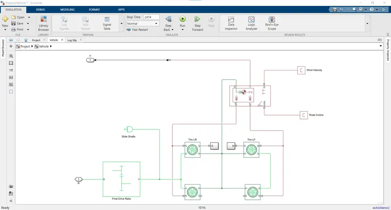
The blocks present in this subsystem are -
- Simple Gear - Simple gear of base and follower wheels with adjustable gear ratio, friction losses, and triggered fault.
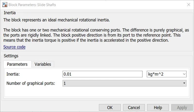
- Inertia - The Inertia block represents an ideal mechanical translational inertia
- Tire (Magic Formula) - The Tire (Magic Formula) block models a tire with longitudinal behavior given by the Magic Formula, an empirical equation based on four fitting coefficients. The block can model tire dynamics under constant or variable pavement conditions.
- Vehicle Body - The Vehicle Body block represents a two-axle vehicle body in longitudinal motion. The vehicle can have the same or a different number of wheels on each axle. The vehicle wheels are assumed identical in size. The vehicle can also have a center of gravity (CG) that is at or below the plane of travel. The block accounts for body mass, aerodynamic drag, road incline, and weight distribution between axles due to acceleration and road profile. Optionally include pitch and suspension dynamics. The vehicle does not move vertically relative to the ground.
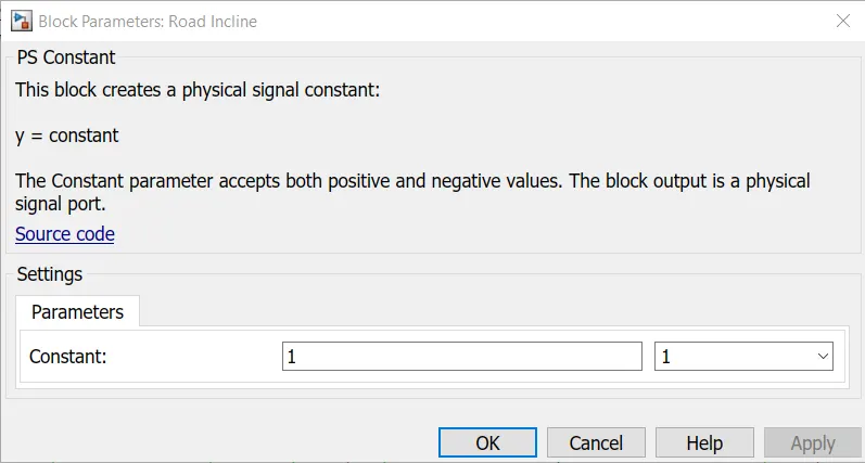
- PS Constant - The PS Constant block generates a physical signal of a constant value. You specify the value and unit of the signal as the Constant parameter.
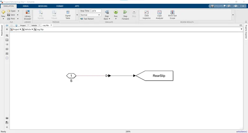
- The Log slip subsystem created using a Goto block and PS-Simulink converter in this vehicle subsystem is shown below -
SOC Estimate - This subsystem is shown below -
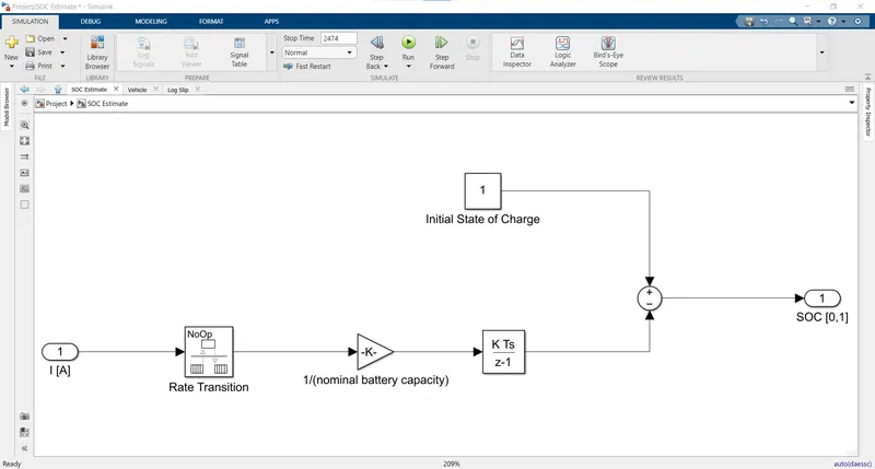
The blocks used are -
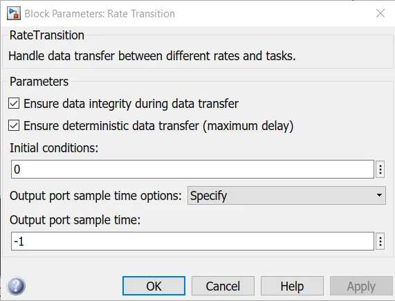
- Rate Transition - The Rate Transition block transfers data from the output of a block operating at one rate to the input of a block operating at a different rate. Use the block parameters to trade data integrity and deterministic transfer for faster response or lower memory requirements.

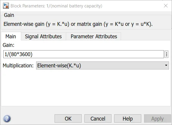
- Gain - The Gain block multiplies the input by a constant value (gain). The input and the gain can each be a scalar, vector, or matrix.

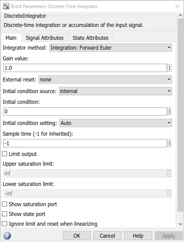
- Discrete Time Integrator - Use the Discrete-Time Integrator block in place of the Integrator block to create a purely discrete model.

- Sum - The Sum block performs addition or subtraction on its inputs. The Add, Subtract, Sum of Elements, and Sum blocks are identical blocks. This block can add or subtract scalar, vector, or matrix inputs. It can also collapse the elements of a signal and perform a summation.

Explanation -
- The drive cycle is provided using Drive Cycle Source Block.
- This is given to the longitudinal driver block at VelRef Port.
- This block provides acceleration and decceleration innputs to the H bridge.
- A controlled pwm voltage is provided for acceleration input.
- The h bridge is the Power converter for the dc motor.
- The dc motor then converts the electrical energy to the mechanical energy.
- The mechanical energy output is fed to the vehicle gear box.
- This gear box controls speed.
- This speed output with inertia is given to the wheels.
- The other parameters like friction froce, aerodynamic force, hill climbing force, and weight distribution is given by vehicle body block.
- The vehicle body provides the velocity as output.
- This is given as feedback to the driver block and can be seen using scope block.
- The State of Charge of battery is estimated by integrating the rate given by rate transtion block and subtracting it from 1.
Input Parameters -
The model input parameters are -
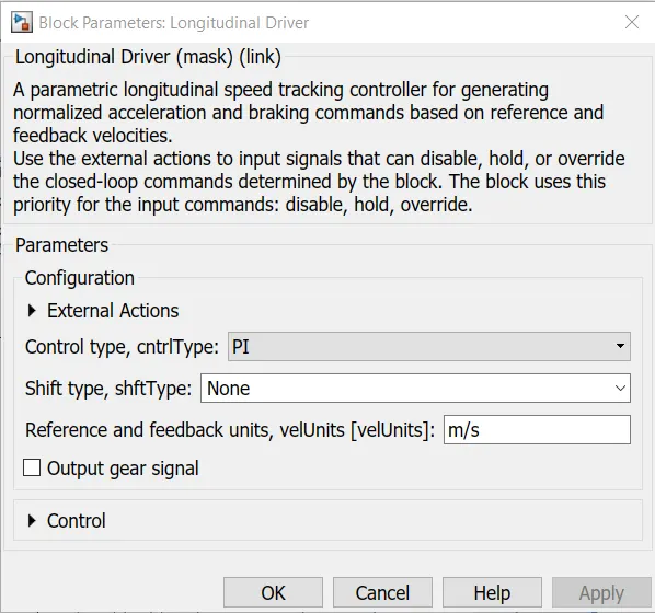
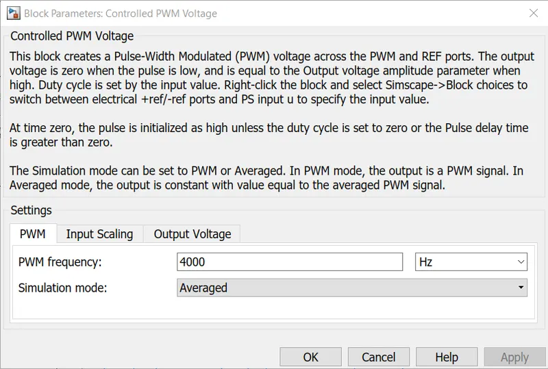
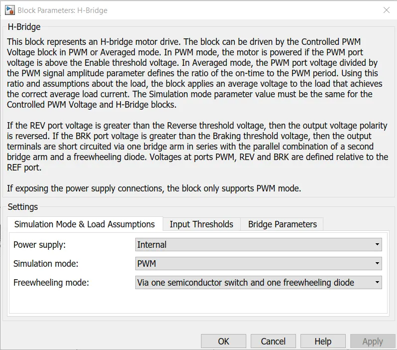
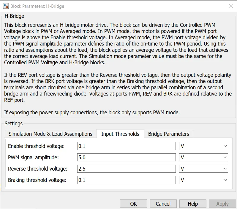
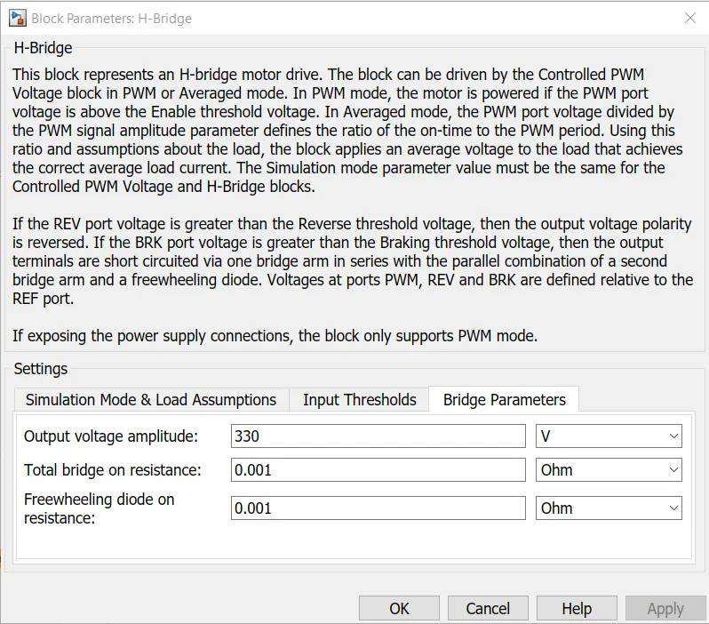
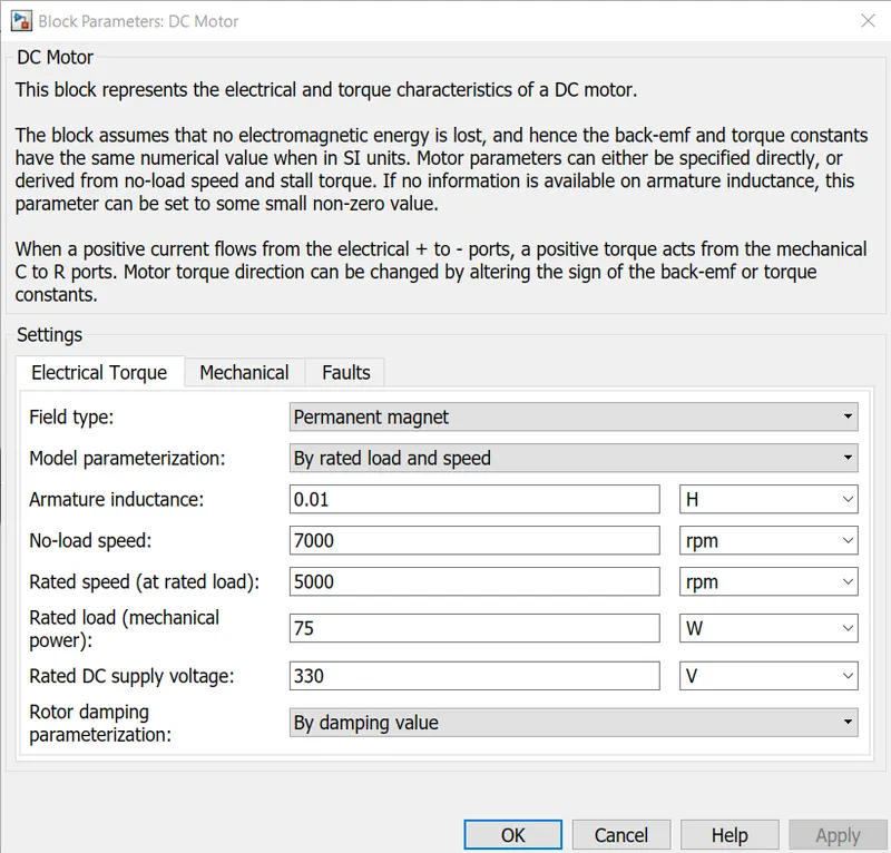
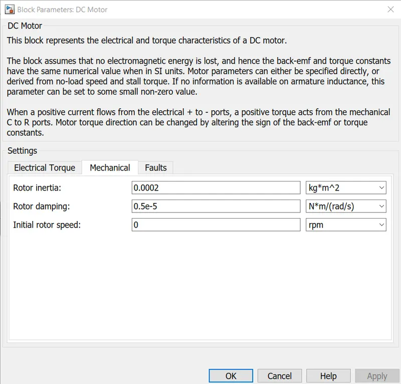
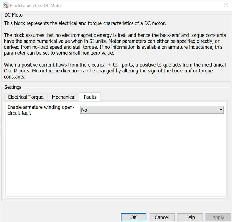
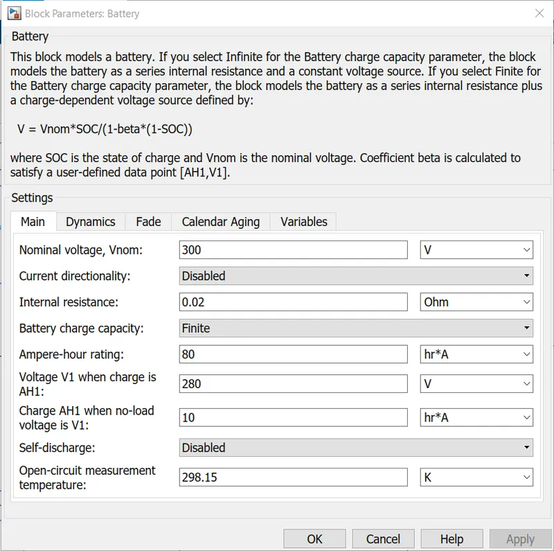
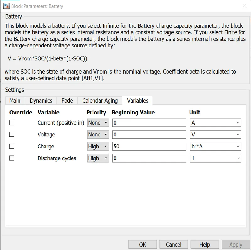
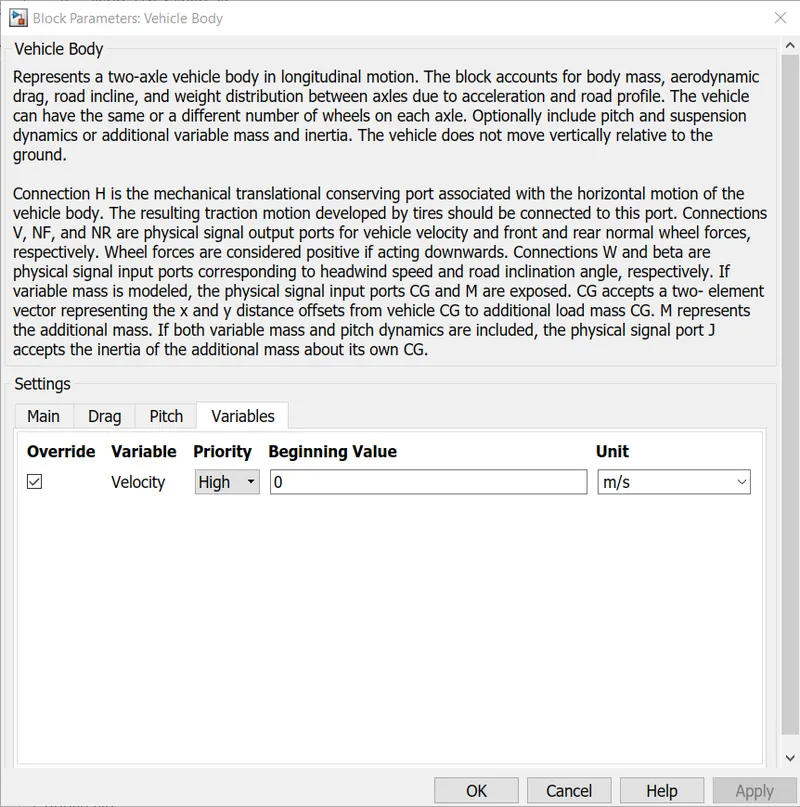
The Vehicle Body subsystem input parameters are
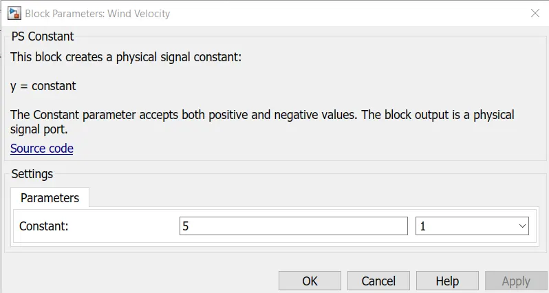
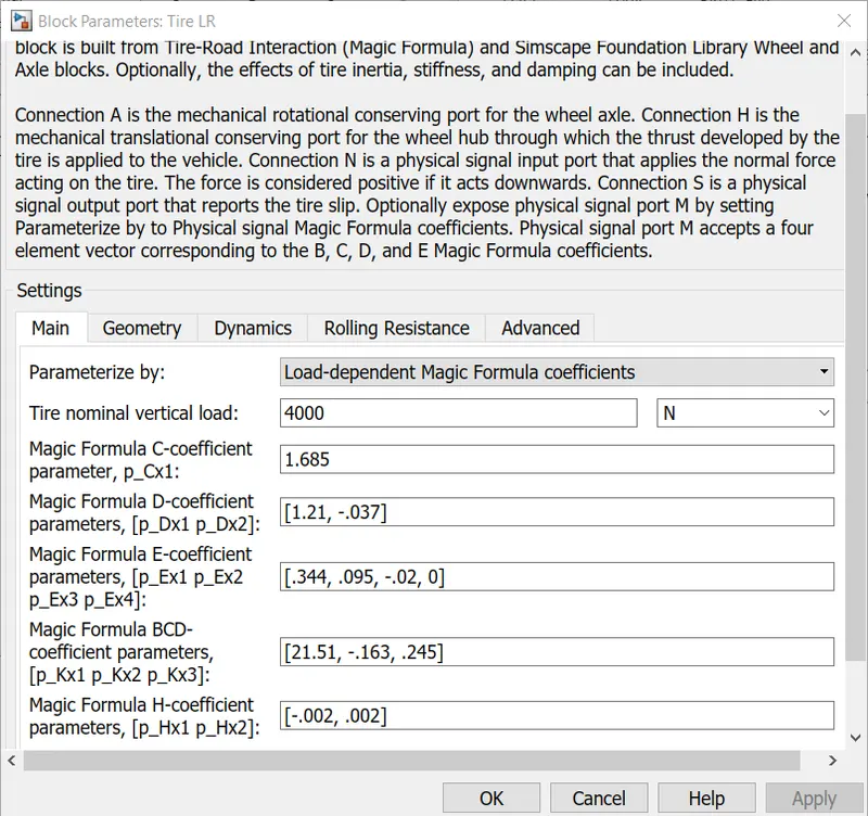
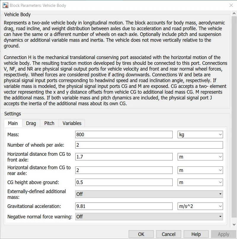
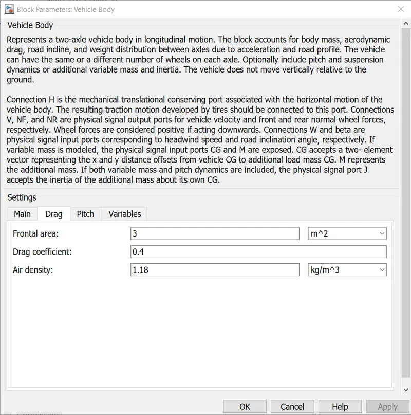
The SOC Estimate Subsystem blocks Input Parameters are
The simulation time is 2474 second.
Results -
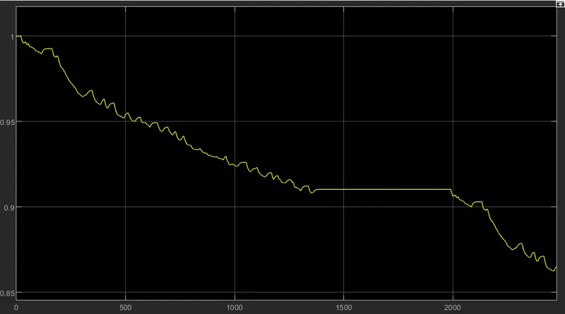
- The SOC % of the battery is given below -
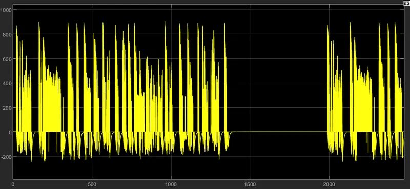
- The current from the battery is
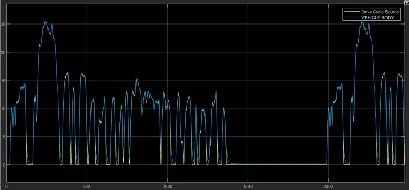
- The speed of vehicle with slip for the given drive cycle -
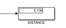
- The distance covered by the vehicle is 5.136 km.
Conclusions -
- The battery is depleted around 15% for the complete driving cycle to cover the distance of 5.136 km.
- The vehicle is follows the drive cycle speed but it cannot follow it perfectly, there are some mismatch in the drive cycle reference speed and speed of vehicle.