Design of an Electric Vehicle
Aim: To model an Electric Vehicle in Simulink.
Objective:
- to make a simple and low run time model using individual component models.
- to check out performance parameters: Speed, SOC, Current, distance, etc with various drive cycles.
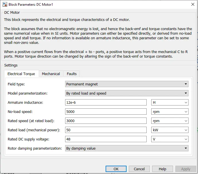
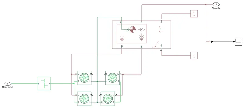
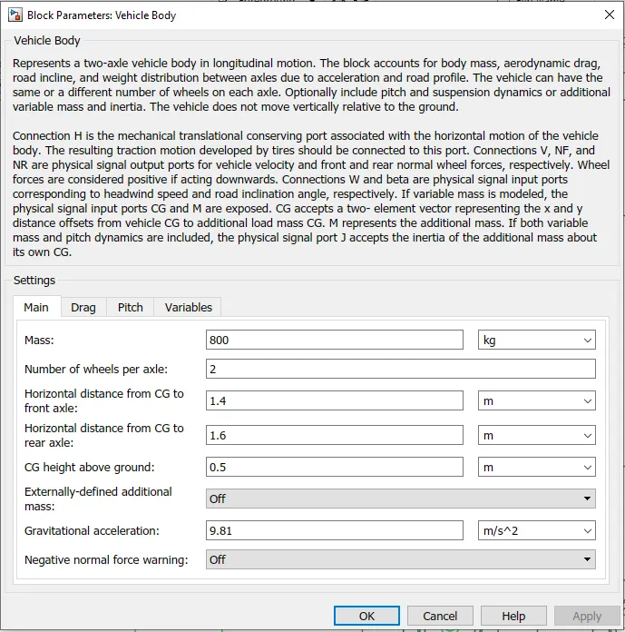
- to play with: Motor power, Vehicle Body, Polling Resistance, Air Drag, Weight inputs, etc.
- to know MATLAB models and their configuration to match with actual vehicle.
Theory:
What is Electric Vehicle Technology:
Operates on an electric motor instead of an IC engine that generates power by burning a mix of fuel and air. This is seen as a possible replacement fot the existing traditional vehicle technology, in wake of the rising pollution, global warming, fossil depletion, etc. Amid the rising carbon footprint of fuel-based vehicles, a lot of vehicle manufacturers such as TATA Motors, Mahindra, Toyota Kirloskar, Ola Electric, etc, have made heavy advances towards the technology. Big players like Tesla, General Motors, Ford, Toyota, Diamler, etc, have already worked on this technology since long in Europe and United States of America.
Major Timeline for EV in India:
- In India, the first concrete decision to incentivise Electric Vehicles was taken in 2010. According to a 95-Cr. scheme approved by Ministry of New and Renewable Energy(MNRE), the govenment anouncecd a financial incentive fpr manufacturers for EVs sold in India.
- In 2013, India unveiled the 'National ELectric Mobility Mission Plan (MEMMP-2020)' to make a major shift to electric vehicles and to address the issues of national energy security, vehicle pollution and growth of domestic manufacturing capabilities.
- In 2017, Nitin Gadkari, the then Transport Minister of India, made a statement showing India's intent to move to 100% electric cars by 2020. However, this was reduced to 30%, due to raised concerns by the automakers.
- In February 2019, the Union Cabinet cleared a fund of 10,000-Cr under the FAME-II scheme. This scheme is to encourage a faster adoption of EV and HEV by offering upfront incentives on purchase of EVs and also by establishing necessary charging infrastructure for EVs. Please click here to know more about FAME-II Scheme.
Classification of Vehicles
Hybrid Electric vehicles:
Today's hybrid electric vehicles (HEVs) are powered by an internal combustion engine in combination with one or more electric motors that use energy stored in batteries. HEVs combine the benefits of high fuel economy and low tailpipe emissions with the power and range of conventional vehicles.
Help from Electric Motor:
In an HEV, the extra power provided by the electric motor may allow for a smaller combustion engine. The battery can also power auxiliary loads and reduce engine idling when the vehicle is stopped. Together, these features result in better fuel economy without sacrificing performance.
Regenerative Braking:
An HEV cannot plug in to off-board sources of electricity to charge the battery. Instead, the vehicle uses regenerative braking and the internal combustion engine to charge. The vehicle captures energy normally lost during braking by using the electric motor as a generator and storing the captured energy in the battery.
Click Here to view an animation showing how HEVs work. To know more about working please click here.
Fuel-Efficient System Design:
HEVs can be either mild or full hybrids, and full hybrids can be designed in series or parallel configurations.
-
Mild hybrids—also called micro hybrids—use a battery and electric motor to help power the vehicle and can allow the engine to shut off when the vehicle stops (such as at traffic lights or in stop-and-go traffic), further improving fuel economy. Mild hybrid systems cannot power the vehicle using electricity alone. These vehicles generally cost less than full hybrids but provide less fuel economy benefit than full hybrids.
-
Full hybrids have larger batteries and more powerful electric motors, which can power the vehicle for short distances and at low speeds. These vehicles cost more than mild hybrids but provide better fuel economy benefits.
There are different ways to combine the power from the electric motor and the engine. Parallel hybrids—the most common HEV design—connect the engine and the electric motor to the wheels through mechanical coupling. Both the electric motor and the internal combustion engine drive the wheels directly. Series hybrids, which use only the electric motor to drive the wheels, are more commonly found in plug-in hybrid electric vehicles.
Plug-In Hybrid Electric Vehicles:
Plug-in hybrid electric vehicles (PHEVs) use batteries to power an electric motor, as well as another fuel, such as gasoline or diesel, to power an internal combustion engine or other propulsion source. PHEVs can charge their batteries through charging equipment and regenerative braking. Using electricity from the grid to run the vehicle some or all of the time reduces operating costs and fuel use, relative to conventional vehicles. PHEVs may also produce lower levels of emissions, depending on the electricity source and how often the vehicle is operated in all-electric mode.
Powered by Electric Motor and Combustion Engine:
PHEVs have an internal combustion engine and an electric motor, which uses energy stored in batteries. PHEVs generally have larger battery packs than hybrid electric vehicles. This makes it possible to drive moderate distances using just electricity (about 15 to 60-plus miles in current models), commonly referred to as the "electric range" of the vehicle.
During urban driving, most of a PHEV's power can come from stored electricity. For example, a light-duty PHEV driver might drive to and from work on all-electric power, plug the vehicle in to charge at night, and be ready for another all-electric commute the next day. The internal combustion engine powers the vehicle when the battery is mostly depleted, during rapid acceleration, or when intensive heating or air conditioning loads are present. Some heavy-duty PHEVs work the opposite way, with the internal combustion engine used for driving to and from a job site and electricity used to power the vehicle's auxiliary equipment or control the cab's climate while at the job site.
Fueling and Driving Options:
PHEV batteries can be charged by an outside electric power source, by the internal combustion engine, or through regenerative braking. During braking, the electric motor acts as a generator, using the energy to charge the battery, thereby recapturing energy that would have been lost. Learn more about charging PHEVs.
PHEV fuel consumption depends on the distance driven between battery charges. For example, if the vehicle is never plugged in to charge, fuel economy will be about the same as a similarly sized hybrid electric vehicle. If the vehicle is driven a shorter distance than its all-electric range and plugged in to charge between trips, it may be possible to use only electric power. Therefore, consistently charging the vehicle is the best way to maximize the electric benefits.
Fuel-Efficient System Design:
Beyond battery storage and motor power, there are various ways to combine the power from the electric motor and the engine. The two main configurations are parallel and series. Some PHEVs use transmissions that allow them to operate in either parallel or series configurations, switching between the two based on the drive profile.
-
Parallel hybrid operation connects the engine and the electric motor to the wheels through mechanical coupling. Both the electric motor and the engine can drive the wheels directly.
-
Series plug-in hybrids use only the electric motor to drive the wheels. The internal combustion engine is used to generate electricity for the motor. Vehicles of this type are often referred to as extended-range electric vehicles. The electric motor drives the wheels almost all of the time, but the vehicle can switch to work like a parallel hybrid at highway speeds when the battery is depleted.
To know more about the working of plug-in hybrids, please click here.
All-Electric Vehicles:
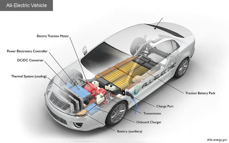
All-electric vehicles (EVs), also referred to as battery electric vehicles, use a battery pack to store the electrical energy that powers the motor. EV batteries are charged by plugging the vehicle in to an electric power source. Although electricity production may contribute to air pollution, the U.S. Environmental Protection Agency categorizes all-electric vehicles as zero-emission vehicles because they produce no direct exhaust or tailpipe emissions.
Driving Range:
Today's EVs generally have a shorter range (per charge) than comparable conventional vehicles have (per tank of gas). However, the increasing range of new models and the continued development of high powered charging equipment is reducing this gap. The efficiency and driving range of EVs varies substantially based on driving conditions. Extreme outside temperatures tend to reduce range, because more energy must be used to heat or cool the cabin. EVs are more efficient under city driving than highway travel. City driving conditions have more frequent stops, which maximize the benefits of regenerative braking, while highway travel typically requires more energy to overcome the increased drag at higher speeds. Compared with gradual acceleration, rapid acceleration reduces vehicle range. Hauling heavy loads or driving up significant inclines also has the potential to reduce range.
Learn more about charging all-electric vehicles.
Please click here to know more about the working of All-Electric Vehicle.
As is well known, EVs use the electricity saved in the battery to cycle the motor and generate the power necessary for driving―this is the biggest difference to internal combustion vehicles, in which the engine exhausts fossil fuel to generate that power. As such, EVs have no need for the engine and transmission, the two of the most crucial components for internal combustion vehicles. Instead, EVs carry several components for electric power: the motor, the battery, the on-board charger, and the Electric Power Control Unit(EPCU). All are essential components to achieve the conversion of the battery’s electricity into the kinetic force that drives the EV forward.
Motor
The motor converts electric energy into kinetic energy that moves the wheels. The advantage of using the motor instead of an engine is numerous: first, the noise and the vibration we typically associate with cars are minimized. Many passengers riding EVs for the first time are surprised by just how quiet and comfortable the ride feels. Moreover, the EV powertrain is smaller than the engine, thus providing lots of additional space for efficient vehicle design―like expanded cabin space or storage.
The motor is also in part an electric generator―it converts the kinetic energy generated while in neutral gear(e.g. while the car is going downhill) into electric energy saved to the battery. The same energy-saving idea applies when the car is reducing its speed, culminating in the so-called “regenerative braking system.” Some of the Hyundai Motor Group’s EVs are equipped with a mechanism that can control the levels of regenerative braking via paddle shifters on the steering wheel, which not only improves the fuel economy but also adds an interesting and fun element to driving.
Reducer
The reducer is a kind of transmission in that it serves to effectively convey the motor’s power to the wheel. But it carries the special name―reducer―for a reason: the motor has a far higher RPM than that of an internal combustion engine, so whereas transmissions change the engine RPM to match the driving circumstance, the reducer must always reduce the RPM to an appropriate level. With the reduced RPM, the EV powertrain can take advantage of the resulting higher torque.
Battery
The battery stores electrical energy and is the equivalent of a fuel tank in an internal combustion engine. The maximum driving distance of an EV is often determined by the battery capacity―the higher the capacity, the higher the driving distance. In that light, increasing the capacity may seem an obvious choice, since high driving distance reduces the annoying need for frequent stops at charging stations. But the choice actually isn’t so obvious, because the battery’s size and weight also have large implications on vehicle performance. The larger and heavier battery takes away from cabin/storage space and worsens the energy efficiency and fuel economy. The best way to optimize performance, then, is to maximize the battery’s energy density―that is, having a small, lightweight battery that stores as much electric energy as possible.
Battery Management System(BMS)
The Battery Management System(BMS) manages the battery’s many cells so that they can operate as if they are a single entity. The EV’s battery consists of as little as tens to as many as thousands of mini-cells, and each cell needs to be in a similar condition to the others in order to optimize the battery’s durability and performance.
Most often, the BMS is built into the battery’s body, though sometimes it is incorporated into the Electric Power Control Unit(EPCU). The BMS mainly oversees the cell’s charge/discharge status, but when it sees a malfunctioning cell, it automatically adjusts the power status of the cell(on/off) through a relay mechanism(the conditional mechanism for opening/closing other circuits).
In lower temperatures, the battery sees a decrease in both charging capacity and speed. The battery heater exists to keep the battery within the ideal temperature range, preventing seasonal performance decreases and maintaining the max driving distance. The system functions while charging as well, ensuring the efficiency of the charge.
On-board Charger(OBC)
The On-board Charger(OBC) is used to convert Alternating Current(AC) from slow chargers or portable chargers used on home outlets into Direct Current(DC). This may make the OBC look similar to the traditional inverter, but they differ crucially in function; the OBC is for charging, and the inverter is for acceleration/deceleration. Incidentally, the OBC is not needed in fast-charging, since fast chargers already supply the electricity in direct current.
Electric Power Control Unit(EPCU)
The Electric Power Control Unit(EPCU) is an efficient integration of nearly all devices that control the flow of the electric power in the vehicle. It consists of the inverter, the Low voltage DC-DC Converter(LDC), and the Vehicle Control Unit(VCU).
1. Inverter
The inverter converts the battery’s DC into AC, which then is used to control the motor speed. The device is responsible for executing acceleration and deceleration, so it serves a crucial part in maximizing the EV’s drivability.
2. Low voltage DC-DC Converter
The LDC converts the high voltage electricity from the EV’s high-voltage battery into low-voltage(12V) and supplies it to the vehicle’s various electronic systems. All electronic systems in the EV use electricity in low voltage, so the high voltage in the battery must be converted first to be useful for these systems.
3. Vehicle Control Unit
As the control tower of all electric power control systems in the vehicle, The VCU is arguably the most important component of the EPCU. It oversees nearly all the vehicle’s power control mechanisms, including the motor control, regenerative braking control, A/C load management, and power supply for the electronic systems.
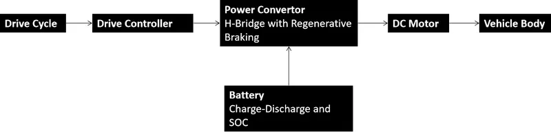
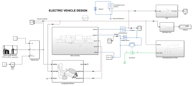
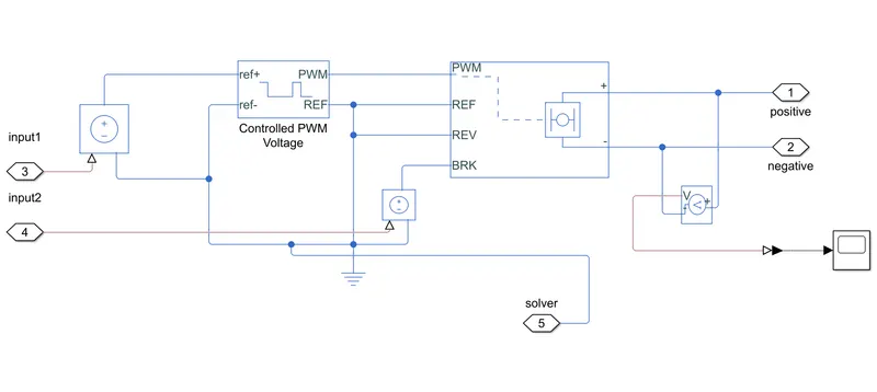
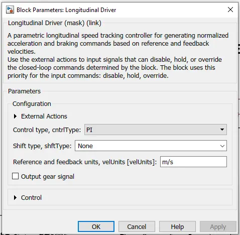
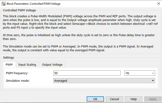
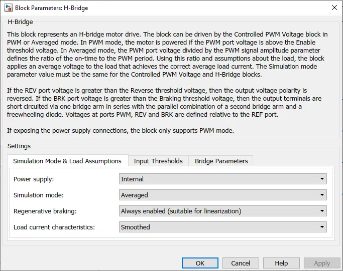
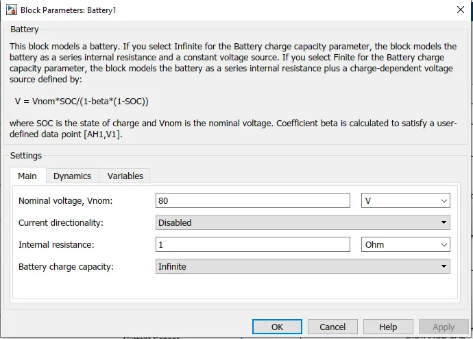
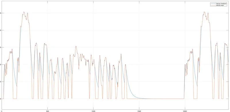
- Feeback Velocity closely traces the velocity input.
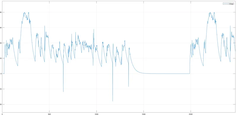
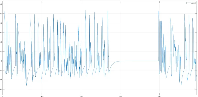
- Voltage consumptions increases with the increased acceleration.
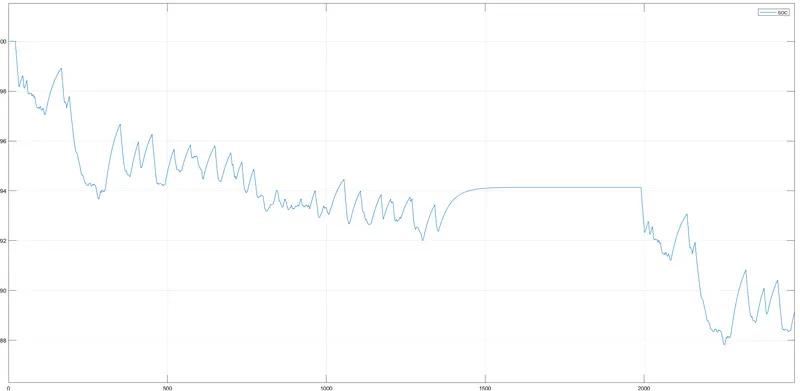
- During regenerative braking the SOC of the battery is increased
- https://www.business-standard.com/about/what-is-electric-vehicle
- https://fame2.heavyindustry.gov.in/
- https://afdc.energy.gov/fueleconomy/animations/hybrids/hybrid/hybridstopped.html
- https://news.hyundaimotorgroup.com/Article/Understanding-EV-Components#:~:text=Instead%2C%20EVs%20carry%20several%20components,that%20drives%20the%20EV%20forward