Final Project: Design of an Electric Vehicle
I am Online batch Student from EV batch -16
Create a MATLAB model of electric car which uses a battery and a DC motor. Choose suitable blocks from Powertrain block set. Prepare a report about your model including following:
Ans)
To derive the model Various blocks and components are needed to get desired output. According to that, these are the blocks which are used to make the EV model.
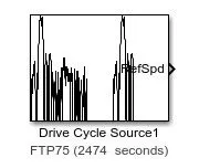
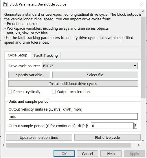
1)Drive Cycle source
- It generates a standard or user-specified longitudinal drive cycle.
- Predicts the engine torque and fuel consumption that
- A vehicle requires to achieve desired speed and acceleration for a given gear shift reference.
- It produces real velocity and shift references for closed-loop acceleration and braking commands for vehicle control and plant models.
2) Longitudinal Driver
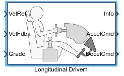
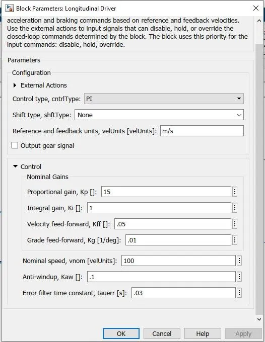
- It implements a longitudinal speed tracking controller. it is based on reference and feedback velocities
the block generates normalized acceleration and braking commands that can vary from 0 through 1. - External actions to input signals can disable, hold or override the closed l00p commands determined by the block.
- Block uses this priority for the input commands: disable, hold, override.
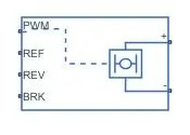
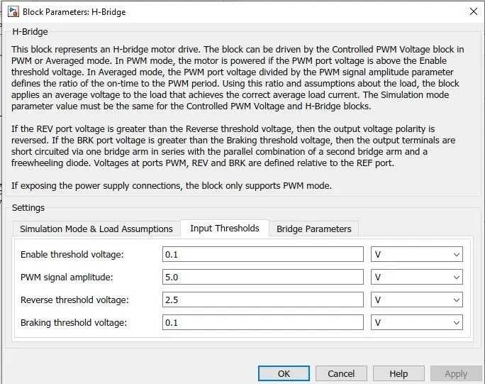
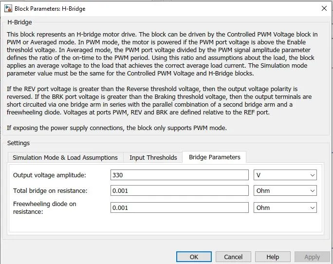
3)H -Bridge
- This block represents an H-bridge motor drive. this block is driven by a controlled PWM voltage block in PWM or averaged mode.
- PWM should be generated and inserted in the input of the H-Bridge.
- In PWM mode the motor is powered if the PWM port voltage is above the Enable threshold voltage.
- In average mode, the PWM port voltage divided by the PWM signal amplitude parameter defines the ratio of the on-time to the PWM period.
- The simulation model parameter value must be the same for the controlled PWM voltage and H-Bridge blocks.
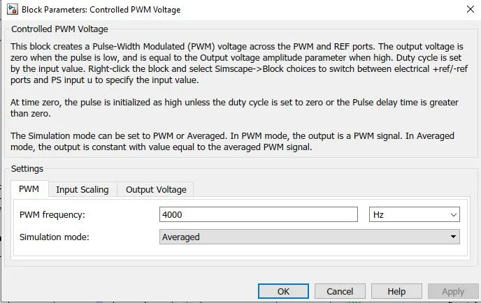
4) Controlled PWM Voltage
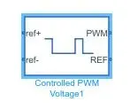
- This block creates a pulse width modulated voltage across the PWM and REF ports.
- The output voltage is zero when the pulse is low and is equal to the output voltage amplitude parameter when high.
- The duty cycle is set by the input value or according to the needed output.
5) DC Motor
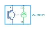
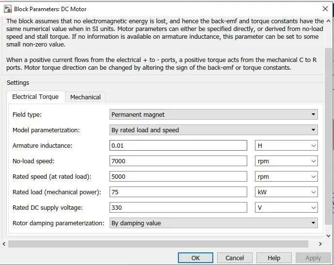
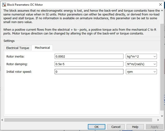
- DC motor represents the electrical characteristics of DC motor.
- It assumes that no electromagnetic energy is lost and hence the back emf and torque constants have the same numerical value.
- Motor parameters can either be directly specified or derived from the no-load speed and
stall torque. - Applying parameters gets desired output.
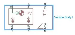
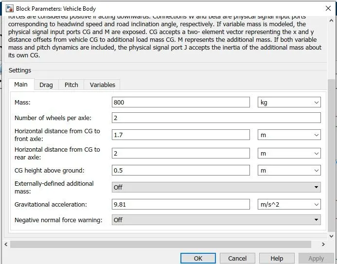
6) Vehicle Body
- The illustrates a two-axle vehicle body in longitudinal motion.
- The vehicle can have the same or a different number of wheels on each axle. The vehicle wheels are assumed identical in size.
- The vehicle can also have a centre of gravity that is at or below the plane of travel.
- These blocks account for body mass, aerodynamic drag, road incline, and weight distribution between axles due to acceleration and road profile.
- It has an option to include an externally-defined mass and externally-defined inertia. The mass, inertia, and centre of gravity of the vehicle body can vary over the course of simulation in response to system changes.
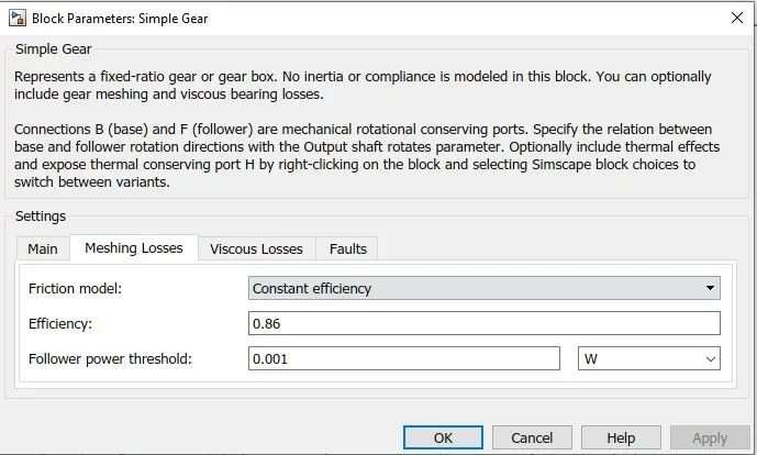
7) Simple Gear
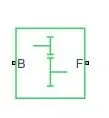
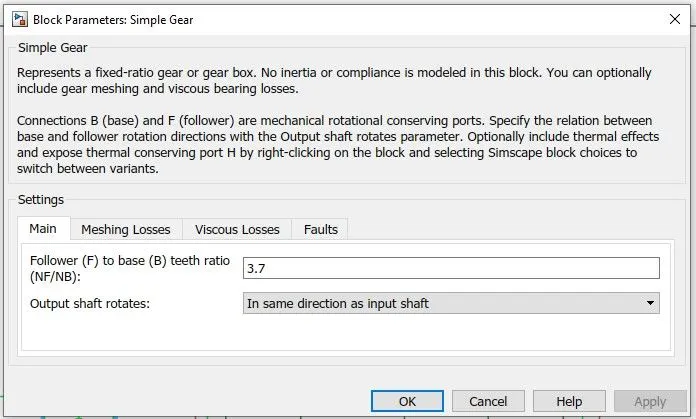
- The Simple Gear has a gearbox that constrains the connected driveline axes of the base gear and the follower gear to corotate with a fixed ratio that you specify.
8) Inertia
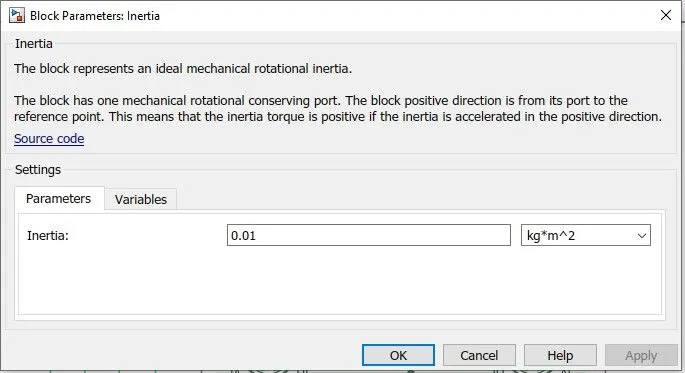
- The Inertia block represents an ideal mechanical rotational inertia.
- The block has one mechanical rotational conserving port. The block's positive direction is from its port to the reference point. This means that the inertia torque is positive if inertia is accelerated in a positive direction.

9) Tire
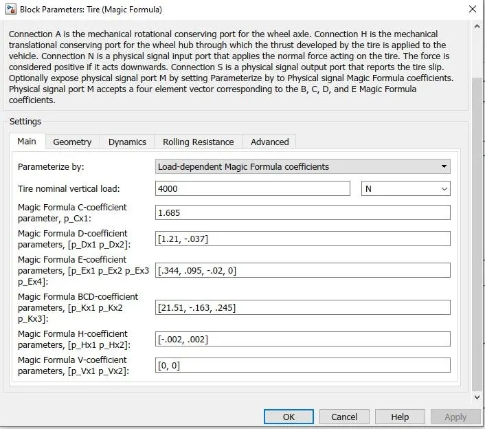
- The Tire block models a tire with longitudinal behaviour is given by the Magic Formula an empirical equation based on four fitting coefficients.
- The block can model tire dynamics under constant or variable pavement conditions.
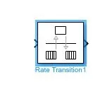
10) Rate transition block
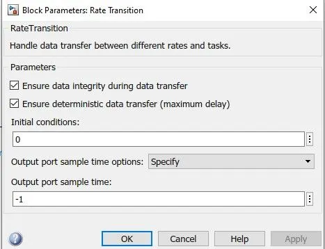
- The Rate Transition block transfers data from the output of a block operating at one rate to the input of a block operating at a different rate.
- The block parameters to trade data integrity and deterministic transfer for faster response or lower memory requirements.
11) Discrere Time Integrator
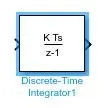
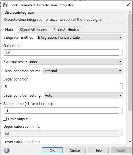
- To create a purely discrete model this block is used.
- To define initial conditions on the block dialogue box or as input to the block.
- To define an input gain. Output block state.
- Reset the state with additional reset input.
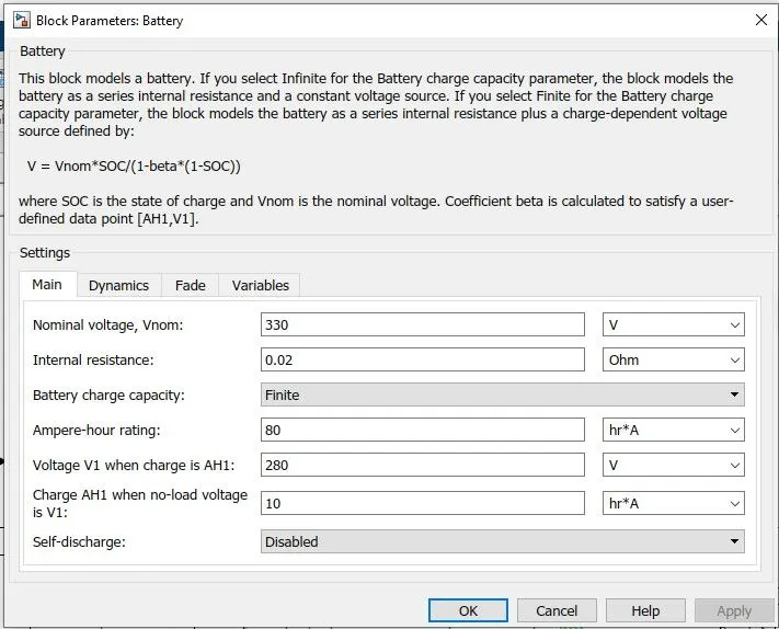
Battery Parameter
Modelling of EV
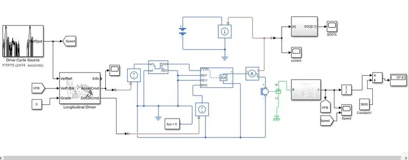
- First of all driving cycle is used as an input for a driver. A longitudinal driver acts as a PI controller where the vehicle's actual speed and reference speed are measured.
- To Run, the DC motor Converter is used which is H- Bridge. According to the motor AC to DC, DC to AC, DC to DC, and AC to AC converter is used to run the motor.
- The converter consists of switches and to on/off PWM(pulse with modulation) technique is used to control the signal and converter.
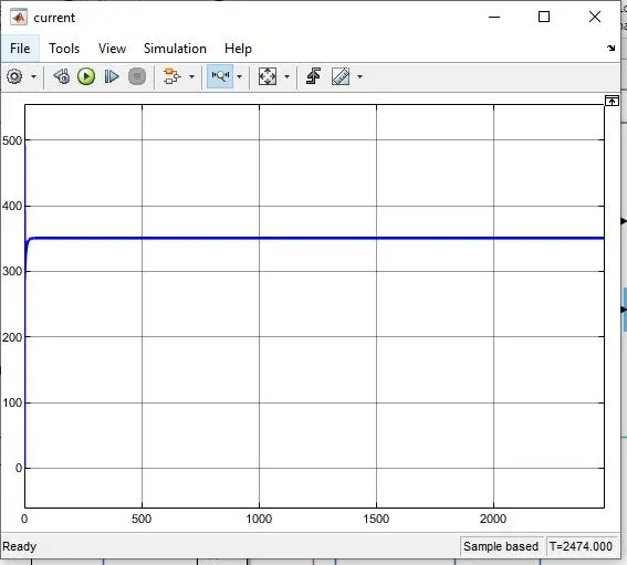
- The battery is used to measure the moving vehicle current from a battery.
- Measurement of speed is constrained by the vehicle body and tires which are allocated in the subsystem.
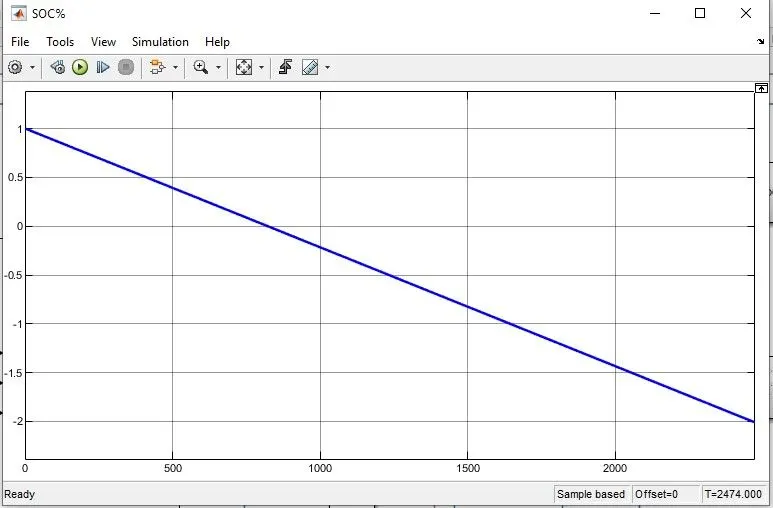
- Another subsystem contains the data to represent the state of charge of a vehicle in a particular time and driving cycle.
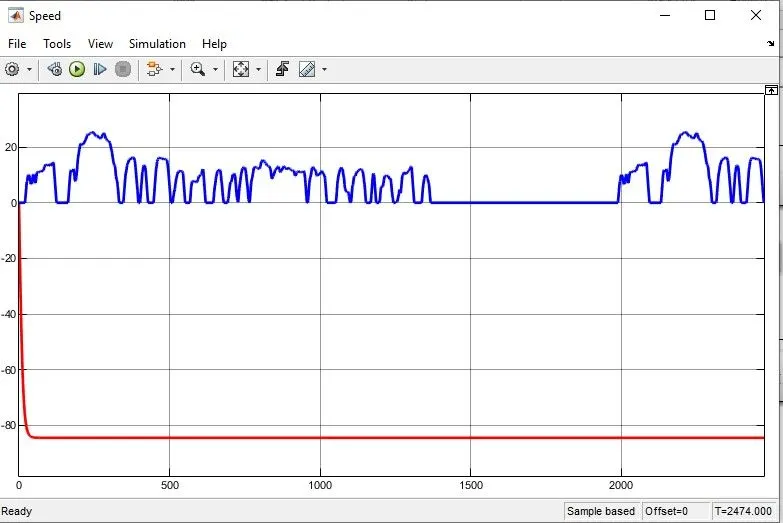
Output Waveforms
SOC%
Current
Speed
Link of Simulink model
https://drive.google.com/file/d/1s4TSu0Vno_l0CDoYe9axGRsy1I-NL2l_/view?usp=sharing