Final Project: Design of an Electric Vehicle
Create a MATLAB model of electric car which uses a battery and a DC motor. Choose suitable blocks from Powertrain block set. Prepare a report about your model including following:
Objectives:
1. System level configurations
2. Model parameters
3. Results
4. Conclusion
Ans:
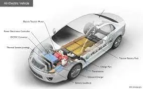
Electric Vehicle:
Electric vehicles have low running costs as they have less moving parts for maintaining and also very environmentally friendly as they use little or no fossil fuels (petrol or diesel).
While some EVs used lead acid or nickel metal hydride batteries, the standard for modern battery electric vehicles is now considered to be lithium ion batteries as they have a greater longevity and are excellent at retaining energy, with a self discharge rate of just 5% per month.
Despite this improved efficiency, there are still challenges with these batteries as they can experience thermal runaway, which have, for example, caused fires or explosions in the Tesla model S, although efforts have been made to improve the safety of these batteries.
Block Diagram of Electric vehicle:
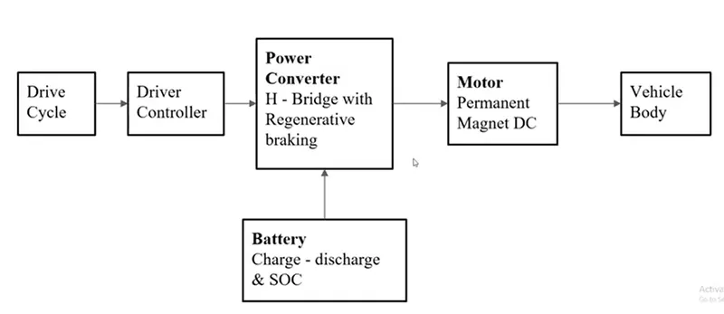
- First Take Vehicle Body.
- Then will be take up a motor will connected the motor to the vehicle body.
- Take a Power converter is nothing but H-Bridge with Regenerative braking will connecte the Battery.
- Battery is supply to the power converter Power converter will actually change the voltage applied to the motor.
- That will actually change the speed of the vehicle.
- Input of the vehicle is Drive Cycle input is connected to the Driver controller
- The Driver Controller is track with actuall speed of the vehical match with given input of the vehicle speed.
This is the about the block diagram
SIMULINK MODEL BLOCK OF ELECTRIC RICKSHAW:
Vehicle Body:
- The Vehicle Body block represents a two-axle vehicle body in longitudinal motion. The vehicle can have the same or a different number of wheels on each axle. For example, two wheels on the front axle and one wheel on the rear axle. The vehicle wheels are assumed identical in size. The vehicle can also have a center of gravity (CG) that is at or below the plane of travel.
- The block accounts for body mass, aerodynamic drag, road incline, and weight distribution between axles due to acceleration and road profile. Optionally include pitch and suspension dynamics. The vehicle does not move vertically relative to the ground.
- The block has an option to include an externally-defined mass and an externally-defined inertia. The mass, inertia, and center of gravity of the vehicle body can vary over the course of simulation in response to system changes.
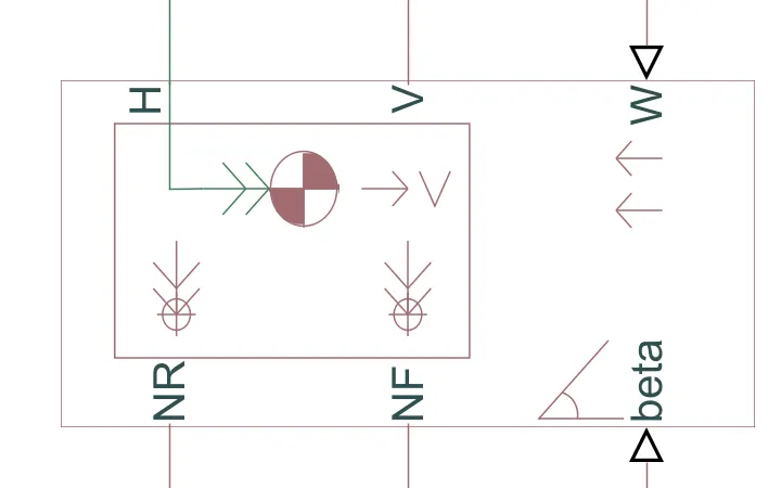
Input Ports of Vehicle Body:
W — Headwind speed, m/s:
- Physical signal input port for headwind speed.
beta — Road incline angle, rad:
- Physical signal input port for road incline angle.
CG — Center of gravity, m:
- Physical signal input port for the center of gravity, in m, of the externally-defined mass relative to the CG of the vehicle body.
M — Mass, kg:
- Physical signal input port for the mass, in kg, of the externally-defined mass.
J — External moment of inertia, kg*m^2:
- Physical signal input port for the moment of inertia, in kg*m^2, of the externally-defined mass.
Output Ports of Vehicle Body:
V — Longitudinal velocity, m/s:
- Physical signal output port for vehicle longitudinal velocity.
NF — Front axle normal force, N:
- Physical signal output port for normal force on the front axle. Wheel forces are considered positive if acting downwards.
NR — Rear axle normal force, N:
- Physical signal output port for normal force on the rear axle. Wheel forces are considered positive if acting downwards.
Conserving Ports of Vehicle Body:
H — Horizontal motion:
- Conserving port associated with the horizontal motion of the vehicle body. Connect tire traction motion to this port.
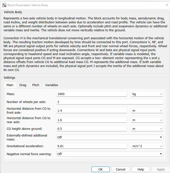
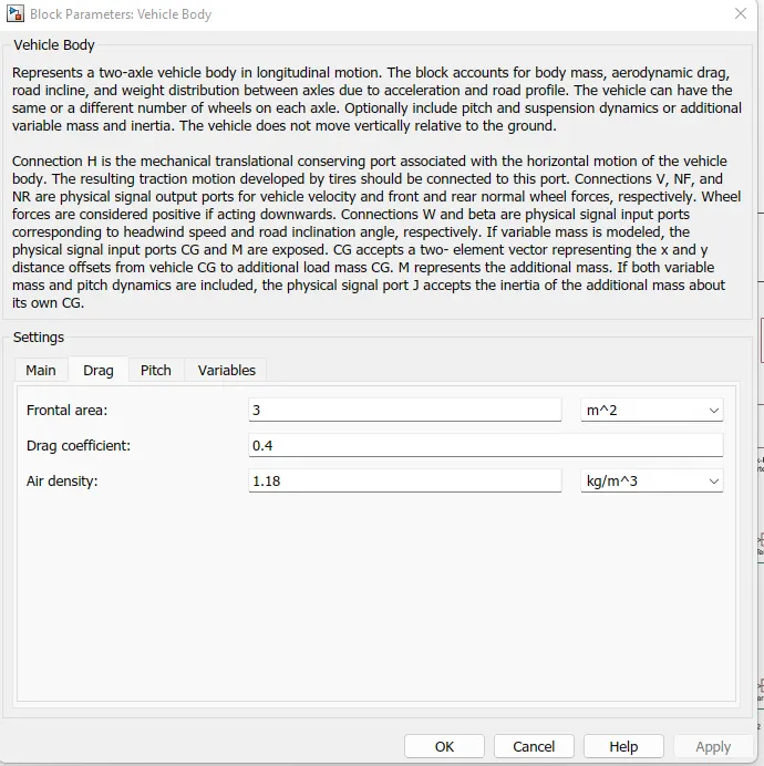
Vehicle Body Parameters Values given Below:
Tire (Magic Formula):
- Tire with longitudinal behavior given by Magic Formula coefficients.
- The Tire (Magic Formula) block models a tire with longitudinal behavior given by the Magic Formula [1], an empirical equation based on four fitting coefficients. The block can model tire dynamics under constant or variable pavement conditions.
- The longitudinal direction of the tire is the same as its direction of motion as it rolls on pavement. This block is a structural component based on the Tire block.
- To increase the fidelity of the tire model, you can specify properties such as tire compliance, inertia, and rolling resistance. However, these properties increase the complexity of the tire model and can slow down simulation. Consider ignoring tire compliance and inertia if simulating the model in real time or if preparing the model for hardware-in-the-loop (HIL) simulation.
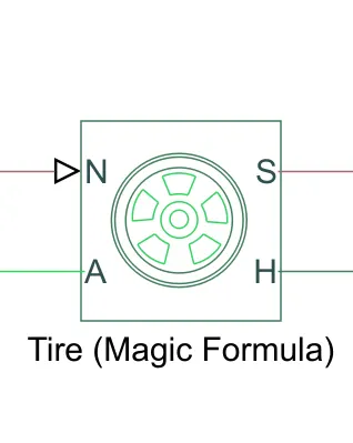
Input Ports of Tire (Magic Formula):
N — Normal force:
- Physical signal input port associated with the normal force acting on the tire. The normal force is positive if it acts downward on the tire, pressing it against the pavement.
M — Magic formula coefficients:
- Physical signal input port associated with the Magic Formula coefficients. Provide the Magic Formula coefficients as a four-element vector, specified in the order [B, C, D, E].
Output Ports of Tire (Magic Formula):
S — Slip:
- Physical signal output port associated with the relative slip between the tire and road.
Conserving Ports of Tire (Magic Formula):
A — Axle:
- Mechanical rotational port associated with the axle that the tire sits on.
H — Hub:
- Mechanical translational port associated with the wheel hub that transmits the thrust generated by the tire to the remainder of the vehicle.
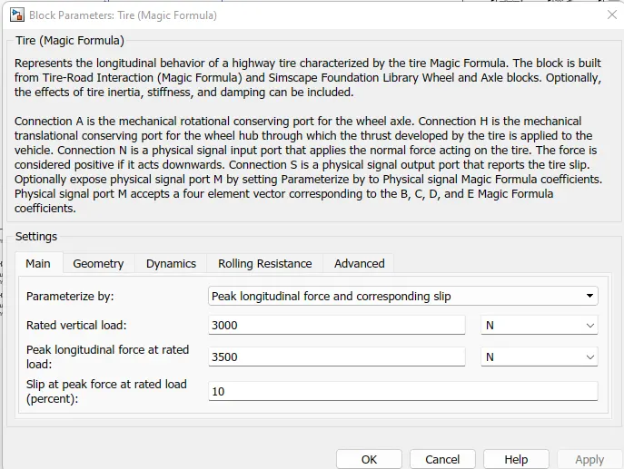
Tire (Magic Formula) Parameters Values given Below:
Inertia:
Ideal mechanical rotational inertia
T=J*dω/dt
where:
-
T is inertia torque.
-
J is inertia.
-
ω is angular velocity.
-
t is time.
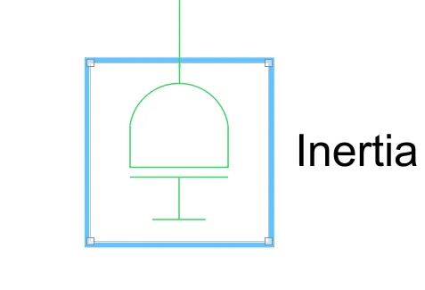
- By default, the block has one mechanical translational conserving port. The block positive direction is from its port to the reference point. This means that the inertia torque is positive if inertia is accelerated in the positive direction.
- In some applications, it is customary to display inertia in series with other elements in the block diagram layout. To support this use case, the Number of graphical ports parameter lets you display a second port on the opposite side of the block icon. The two-port variant is purely graphical: the two ports have the same angular velocity, so the block functions exactly the same whether it has one or two ports. The block icon changes depending on the value of the Number of graphical ports parameter.
Conserving Ports of Inertia:
I — Port that connects inertia to the circuit:
- Mechanical rotational conserving port that connects the inertia to the physical network.
J — Second graphical port:
- Second mechanical rotational conserving port that lets you connect the inertia in series with other elements in the block diagram. This port is rigidly connected to port I, therefore the difference between the one-port and two-port block representations is purely graphical.
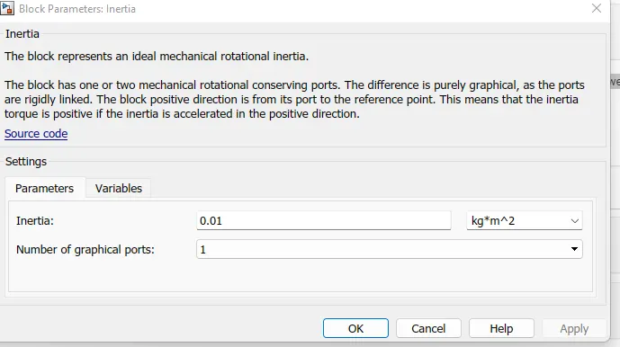
Inertia Parameters Values given Below:
Simple Gear:
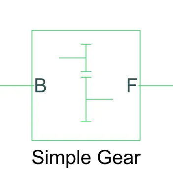
- Simple gear of base and follower wheels with adjustable gear ratio, friction losses, and triggered faults.
- The Simple Gear block represents a gearbox that constrains the connected driveline axes of the base gear, B, and the follower gear, F, to corotate with a fixed ratio that you specify. You choose whether the follower axis rotates in the same or opposite direction as the base axis. If they rotate in the same direction, the angular velocity of the follower, ωF, and the angular velocity of the base, ωB, have the same sign. If they rotate in opposite directions, ωF and ωB have opposite signs.
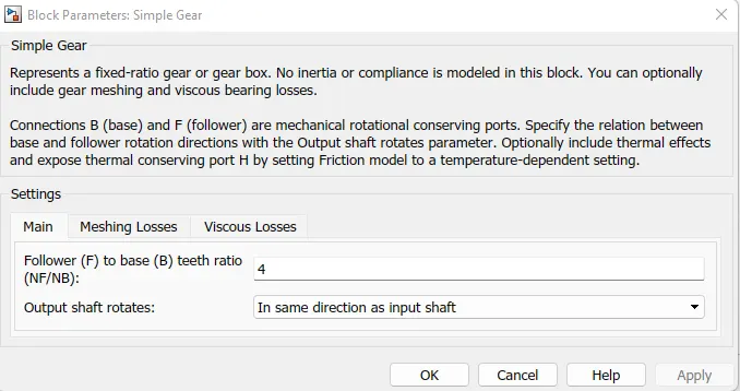
Simple Gear Parameters Values given Below:
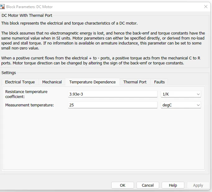
DC Motor:
- DC motor model with electrical and torque characteristics and fault modeling.
- The DC Motor block represents the electrical and torque characteristics of a DC motor using the following equivalent circuit model:
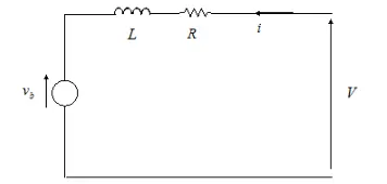
- You specify the equivalent circuit parameters for this model when you set the Model parameterization parameter to
By equivalent circuit parameters. The resistor R corresponds to the resistance you specify in the Armature resistance parameter. The inductor L corresponds to the inductance you specify in the Armature inductance parameter.
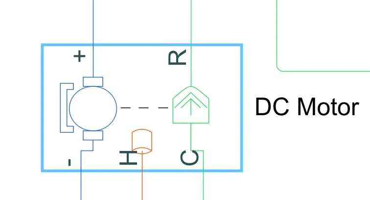
Conserving Ports of DC Motor:
+ — Positive terminal:
- Electrical conserving port associated with the DC motor positive terminal.
- — Negative terminal:
C — Motor case:
- Mechanical rotational conserving port associated with the DC motor case.
R — Motor rotor:
- Mechanical rotational conserving port associated with the DC motor rotor.
F+ — Positive field:
- Electrical conserving port associated with the positive field winding.
F- — Negative field:
- Electrical conserving port associated with the negative field winding.
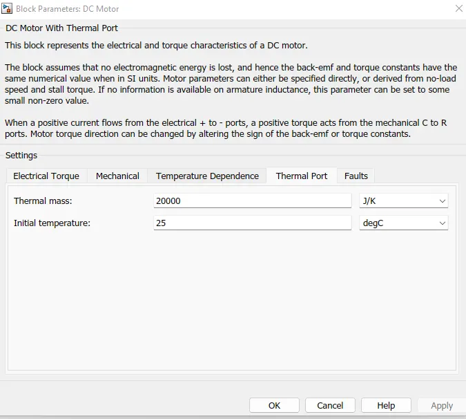
H — Thermal port:
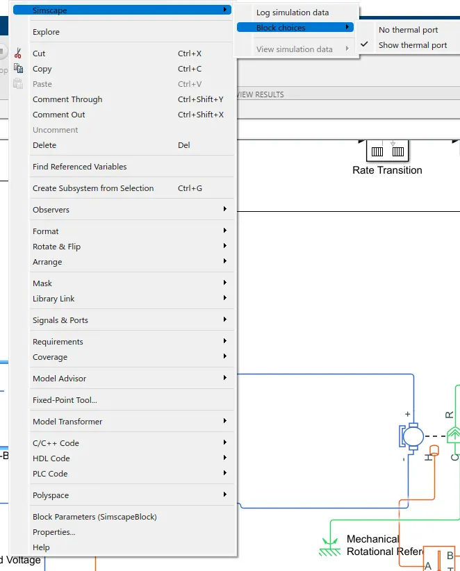
- The block has an optional thermal port, hidden by default. To expose the thermal port, right-click the block in your model, and then from the context menu select Simscape > Block choices > Show thermal port. This action displays the thermal port H on the block icon, and exposes the Temperature Dependence and Thermal Port parameters.
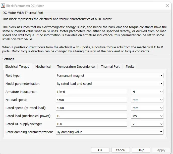
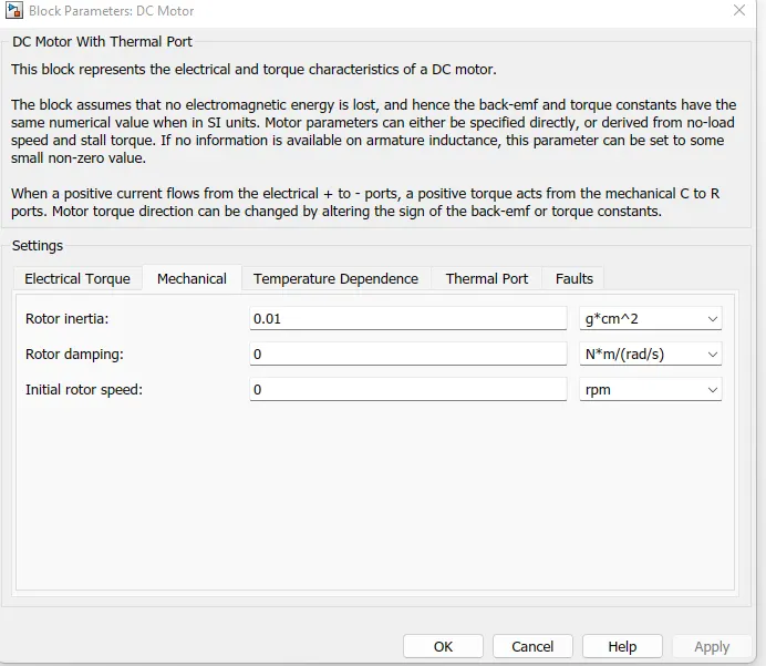
DC Motor Parameters Values given Below:
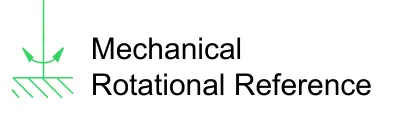
Mechanical Rotational Reference:
- This block represents a mechanical rotational reference point, that is, a frame or a ground. Use it to connect mechanical rotational ports that are rigidly affixed to the frame (ground).
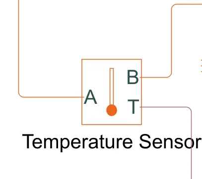
Temperature Sensor:
- This block measures temperature in a thermal network. There is no heat flow through the sensor. The physical signal port T reports the temperature difference across the sensor. The measurement is positive when the temperature at port A is greater than the temperature at port B.
Thermal Reference:
- This block represents a reference point in a thermal network where the temperature is equal to absolute zero.

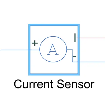
Current Sensor:
- The block represents an ideal current sensor, that is, a device that converts current measured in any electrical branch into a physical signal proportional to the current.
- Connections + and - are conserving electrical ports through which the sensor is inserted into the circuit. Connection I is a physical signal port that outputs current value.
H-Bridge:
- The H-Bridge block represents an H-bridge motor driver. The block has the following two Simulation mode options:
-
PWM— The H-Bridge block output is a controlled voltage that depends on the input signal at the PWM port. If the input signal has a value greater than the Enable threshold voltage parameter value, the H-Bridge block output is on and has a value equal to the value of the Output voltage amplitude parameter. If it has a value less than the Enable threshold voltage parameter value, the block maintains the load circuit using one of the following three Freewheeling mode options:-
Via one semiconductor switch and one freewheeling diode -
Via two freewheeling diodes -
Via two semiconductor switches and one freewheeling diode
The first and third options are sometimes referred to as synchronous operation.
The signal at the REV port determines the polarity of the output. If the value of the signal at the REV port is less than the value of the Reverse threshold voltage parameter, the output has positive polarity; otherwise, it has negative polarity.
-
-
Averaged— This mode has two Load current characteristics options:-
Smoothed -
Unsmoothed or discontinuous
The
Smoothedoption assumes that the current is practically continuous due to load inductance. In this case, the H-Bridge block output is:VOVPWMAPWM−IOUTRON
where:
-
VO is the value of the Output voltage amplitude parameter.
-
VPWM is the value of the voltage at the PWM port.
-
APWM is the value of the PWM signal amplitude parameter.
-
IOUT is the value of the output current.
-
RON is the Bridge on resistance parameter.
-
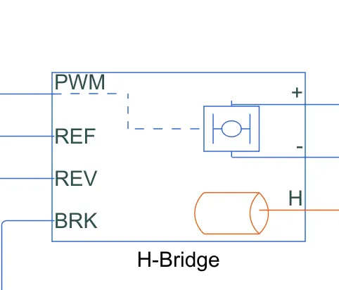
Conserving Ports of H-Bridge:
+ — Positive load connection port:
- Electrical conserving port associated with the positive load connection.
- — Negative load connection port:
- Electrical conserving port associated with the negative load connection.
V+ — Positive supply connection:
- Electrical conserving port associated with the positive electrical supply connection.
V- — Negative supply connection:
- Electrical conserving port associated with the negative electrical supply connection.
PWM — Pulse-width modulated signal:
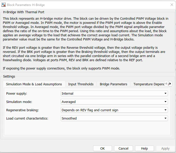
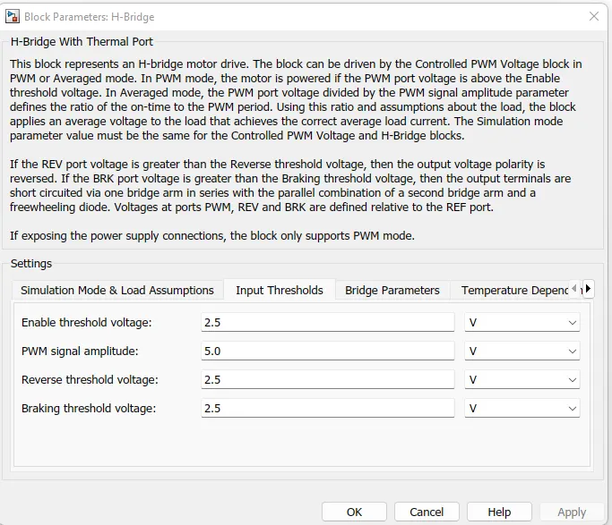
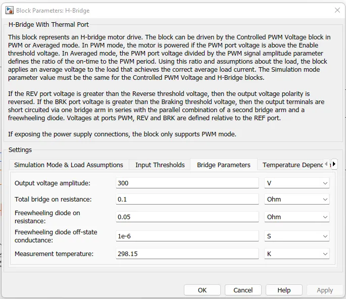
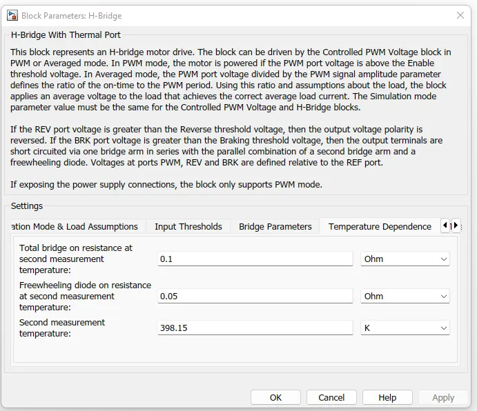
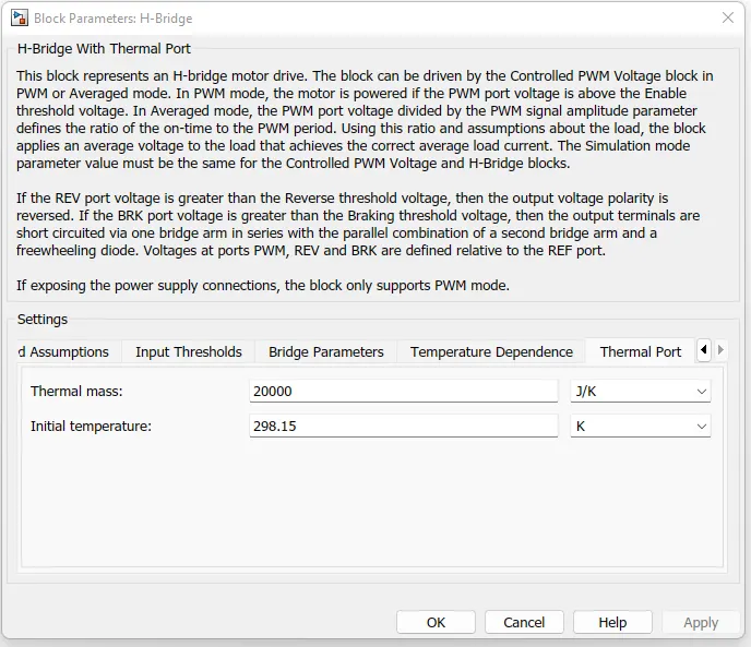
H-Bridge Parameters Values given Below:
Controlled PWM Voltage:
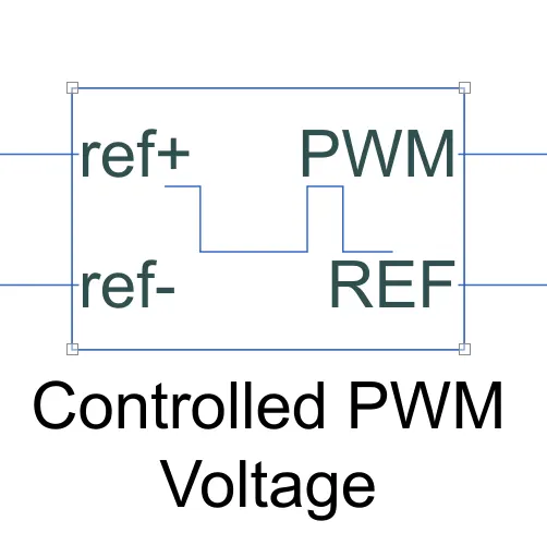
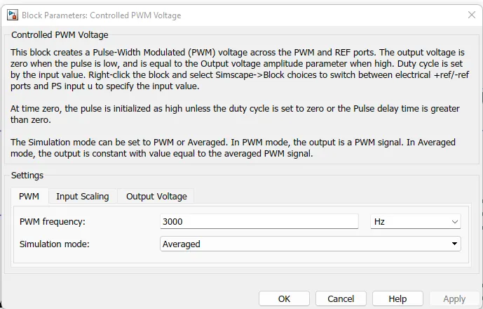
- This block creates a Pulse-Width Modulated (PWM) voltage across the PWM and REF ports. The output voltage is zero when the pulse is low, and is equal to the Output voltage amplitude parameter when high. Duty cycle is set by the input value. Right-click the block and select Simscape->Block choices to switch between electrical +ref/-ref ports and PS input u to specify the input value.
- At time zero, the pulse is initialized as high unless the duty cycle is set to zero or the Pulse delay time is greater than zero.
- The Simulation mode can be set to PWM or Averaged. In PWM mode, the output is a PWM signal. In Averaged mode, the output is constant with value equal to the averaged PWM signal.
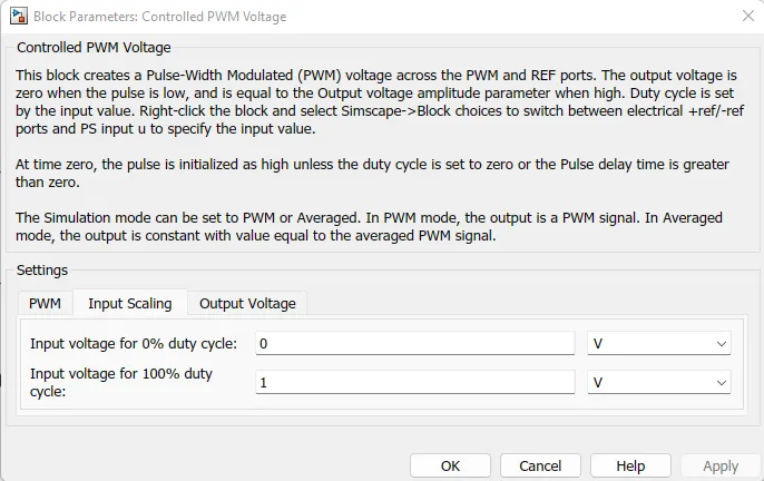
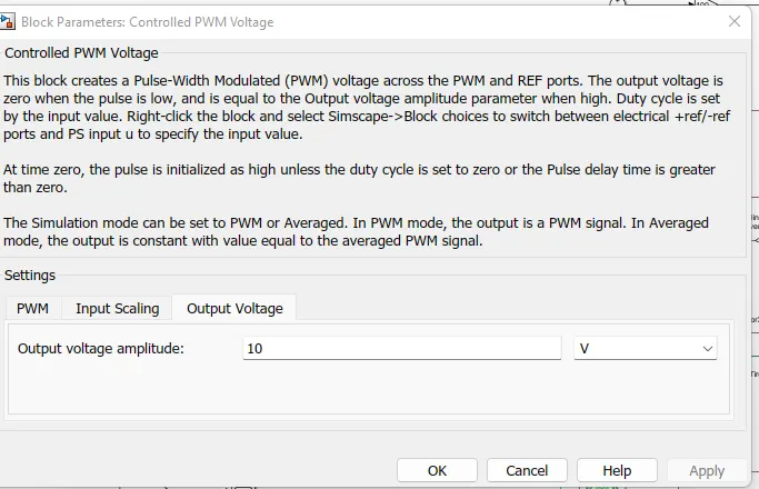
Controlled PWM Voltage Parameters Values given Below:
Controlled Voltage source:
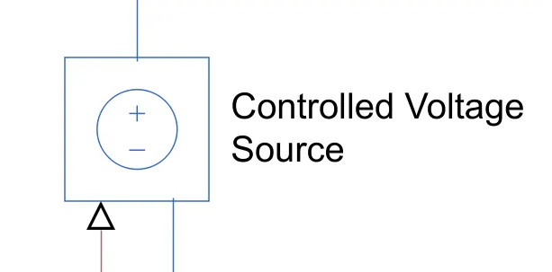
- The block represents an ideal voltage source that is powerful enough to maintain the specified voltage at its output regardless of the current passing through it. The output voltage is V = Vs, where Vs is the numerical value presented at the physical signal port.
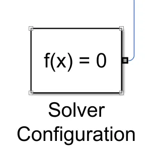
Solver Configuration:
- Each physical network represented by a connected Simscape™ block diagram requires solver settings information for simulation. The Solver Configuration block specifies the solver parameters that your model needs before you can begin simulation.
- Each topologically distinct Simscape block diagram requires exactly one Solver Configuration block to be connected to it.
Electrical Reference:
- Electrical reference port. A model must contain at least one electrical reference port (electrical ground).
Simulink-PS Converter:
- The unit expression in 'Input signal unit' parameter is associated with the Simulink input signal and determines the unit assigned to the Physical Signal.
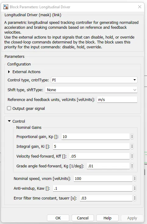
Longitudinal Driver:
- The Longitudinal Driver block implements a longitudinal speed-tracking controller. Based on reference and feedback velocities, the block generates normalized acceleration and braking commands that can vary from 0 through 1. You can use the block to model the dynamic response of a driver or to generate the commands necessary to track a longitudinal drive cycle.
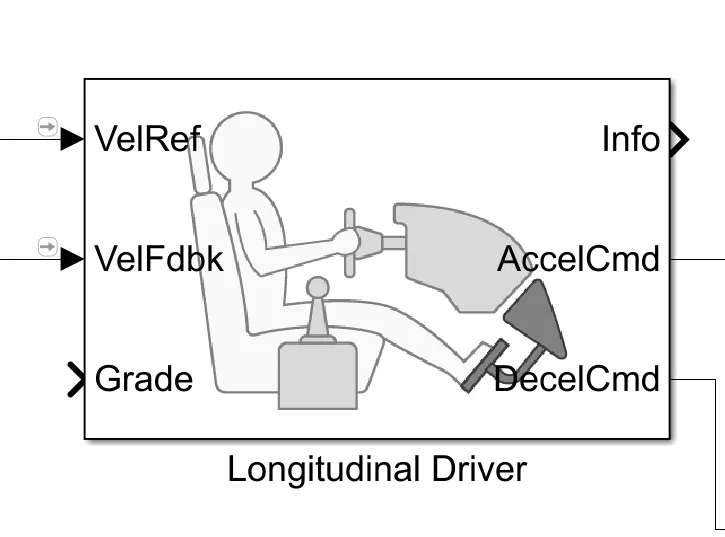
Input Ports of Longitudinal Drier:
VelRef — Reference vehicle velocity:
- Reference velocity, vref, in m/s.
VelFdbk — Longitudinal vehicle velocity:
- Longitudinal vehicle velocity, U, in the vehicle-fixed frame, in m/s.
Grade — Road grade angle:
- Road grade angle, θ or γ, in deg.
Output Ports of Longitudinal Drier:
Info — Bus signal
AccelCmd — Commanded vehicle acceleration:
- Commanded vehicle acceleration, yacc, normalized from 0 through 1.
DecelCmd — Commanded vehicle deceleration
- Commanded vehicle deceleration, ydec, normalized from 0 through 1.
Longitudinal Driver Parameters Values given Below:
Battery:
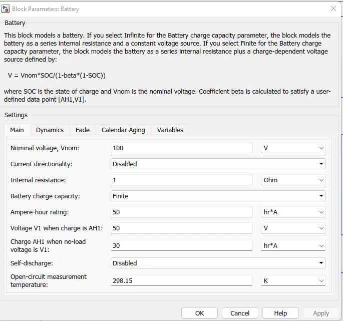
This block models a battery. If you select Infinite for the Battery charge capacity parameter, the block models the battery as a series internal resistance and a constant voltage source. If you select Finite for the Battery charge capacity parameter, the block models the battery as a series internal resistance plus a charge-dependent voltage source defined by:
V = Vnom*SOC/(1-beta*(1-SOC))
where SOC is the state of charge and Vnom is the nominal voltage. Coefficient beta is calculated to satisfy a user-defined data point [AH1,V1].
Battery Parameters Values given Below:
Controlled current Source:
The block represents an ideal current source that is powerful enough to maintain the specified current through it regardless of the voltage across it. The output current is I = Is, where Is is the numerical value presented at the physical signal port.
Vehicle Body Transmission system:
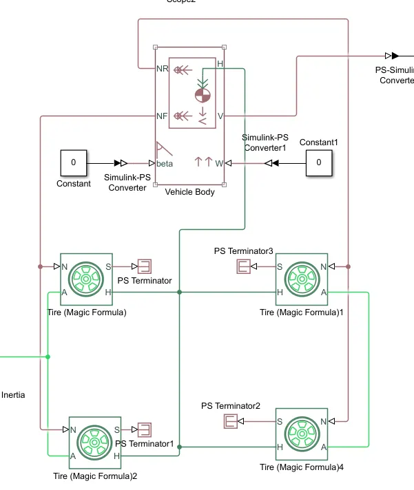
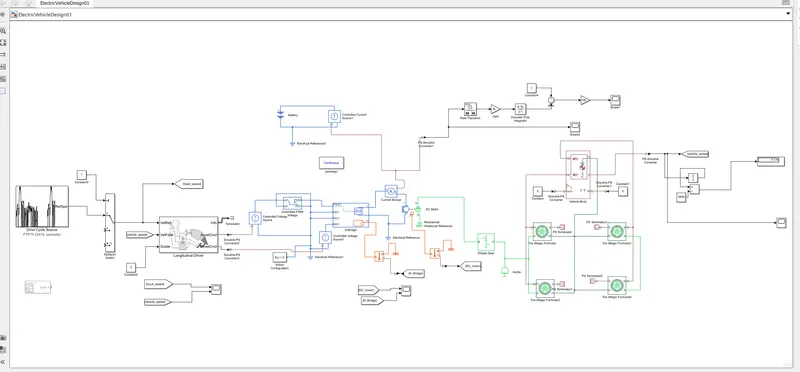
- As we know transmission is the main part of the vehicle which is used to supply the propulsion powers from the motor and the battery to the wheels.under transmission the number of components comes which are wheels,gearbox,throttle,power input etc.
- In this transmission system blocks used are Tire and vvehicle Body. There are 4 tire blocks used as 4 wheels of the vehicle and here we have connected the gearrbox with the rear wheel to make it a rear wheel drive.
- The vehicle body block is been connected to these wheels by all the input and output ports.In vehicle body block we have connected as ps constant block to beta and wind velocity as we have assumed both as zreo and hub motor port is also connected with the wheels H port.
DC Motor system:
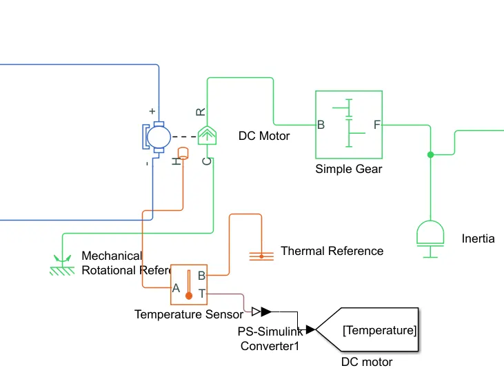
- The Dc motor output terminals are connected in other parameters R terminal is connected in simple Gear system block Input terminal of the B is connected and Gear block output terminal F is connected input of the vehicle Body terminals.
- Motor C terminal is connected in Mechanical Rotational reference. Temperature Sensor block are used sensing the temperature of the Dc motor.PS-Simulink converter is used to the convert the physical signal to simulink signal and thermal reference are useing.
Motor Controller system:
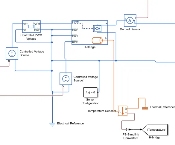
- This motor controller system contains H-bridge and a Controlled PWM voltage block.H-bridge block is used to the supply power from the battery to the dc motor.H-bridge has 4 switches that give the controlled DC voltage supply to the DC motor and we can also control the supply of voltage.
- Here we have enabled the thermal output of the H-bridge controller to get the temperature output of the controller while the vehicle is in motion.In H-Bridge we have control on PWM voltage Reverse and Braking effect also.
- As below we can see block parameters, for simulation mode we have two options internal and external as we choose internally we have a choice of PWM mode and averaged mode.
- In PWM mode the simulation time increases drastically as if the simulation time is of 5secs then PWM mode is effective but as now our simulation time is in mins or hours so here averaged mode is been chosen as it is faster compared to PWM mode.
- Also we have to change the output voltage amplitude to the voltage we have supplied to the DC motor.As from the controlled PWM vlotage block which is connected to the input PWM pin in the H-bridge block.
- This block will apply pulses and based on these pulses from the fixed battery voltage variable output voltage will be available to the motor torque are changed.
- so basically this subsystem will control the power supply to the DC motor using the following blocks.
Steps for enabling thermal output of H-Bridge:
- First select the block and right click on the block we will get multiple options from which we have to select simscape block choices show thermal port.
SOC Calculation:
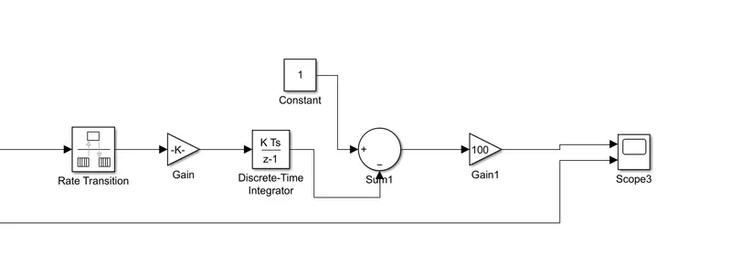
- here in this subsystem there is the number of blocks used are rate transition gain, constant,sum,Discrete time integrator,etc.
- rate transition block takes input from the controlled current source block as soc input signals and do a sampling of the signals and gives to gain block.
- gain block multiplies the sampling signal with the rated voltage and gives it to the Discrete-time integrator block.Discrete-time integrator block integrates the signal and adds it to the constant given and supply is to the gain block again.
- Gain block multiplies it with the 100 and gives it to the SOC output.
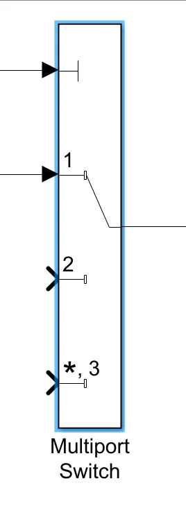
Multiport Switch:
Pass through the input signals corresponding to the truncated value of the first input. The inputs are numbered top to bottom (or left to right). The first input port is the control port. The other input ports are data ports.
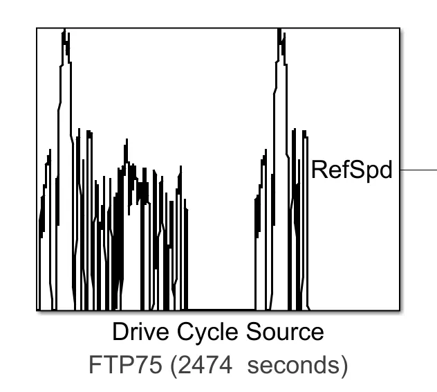
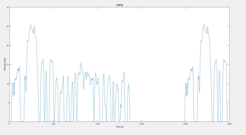
Input Drive Cycle Source is FTP75:
- Generates a standard or user-specified longitudinal drive cycle. The block output is the vehicle longitudinal speed. You can import drive cycles from:
- - Predefined sources
- - Workspace variables, including arrays and time series objects
- - mat, xls, xlsx, or txt files
- Use the fault tracking parameters to identify drive cycle faults within specified speed and time tolerances.
COMPLETE SIMULINK MODEL:
OUTPUT RESULTS:
For FTP75 Drive Cycle:
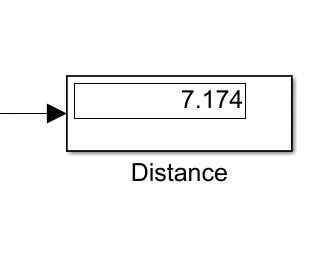
- By running the vehicle with FTP75 Drive cycle for 2474 see the distance traveled is 7.174 .The gear ratio in the simple gearbox is kept at 4.
Input speed and Vehicle Speed:
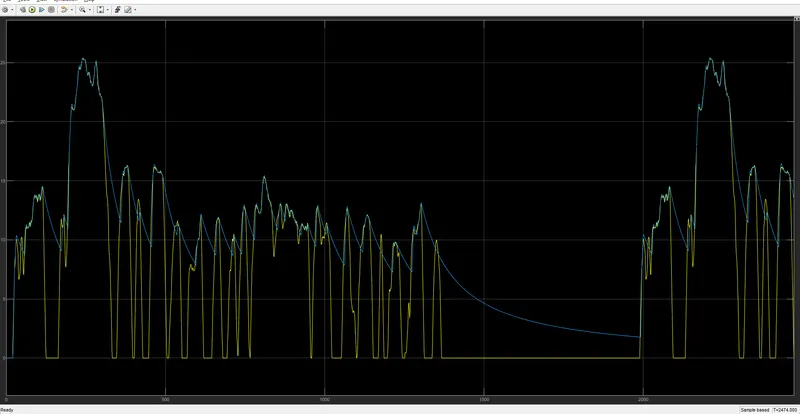
- As we can see we got the velocity profile almost completely following the drive cycle data with the maximum speed reaching UP to 25km/hr.
DC Motor and H-Bridge Temperature:
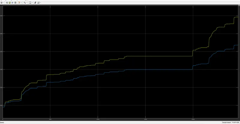
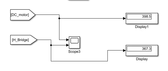
- The Temperature of the moto is increased to 398.5degree celcius ,the Temperature of the controller is 367.3degree celcius with 20000 as the thermal mass given both to the motor and the H-bridge.
SOC(state of charge)Output:
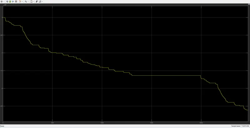
- In this graph state of charge of the battery decreases with time
- In the SOC graph the speed spikes show regenerative braking is considered.