Final Project: Design of an Electric Vehicle
Create a MATLAB model of electric car which uses a battery and a DC motor. Choose suitable blocks from Powertrain block set.
- The MATLAB model of an electric car using battery and motor is simulated in Simulink.
- Here the dynamics of vehicle motion is represented by drive cycles.
- Firstly, the vehicle system is formulated by using the simscape components: vehicle body, tire and inertia as shown below:
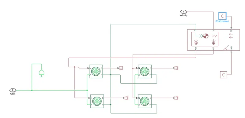
Vehicle body:
- Represents a two-axle vehicle body in longitudinal motion.
- The block accounts for body mass, aerodynamic drag, road incline, and weight distribution between axles due to acceleration and road profile.
- The vehicle can have the same or a different number of wheels on each axle.
- Connection H is the mechanical translational conserving port associated with the horizontal motion of the vehicle body. The resulting traction motion developed by tires should be connected to this port.
- Connections V, NF, and NR are physical signal output ports for vehicle velocity and front and rear normal wheel forces, respectively.
- Connections W and beta are physical signal input ports corresponding to headwind speed and road inclination angle, respectively. (In the simulation, wind speed and road inclination are neglected)
Tires:
- Represents the longitudinal behavior of a highway tire characterized by the tire Magic Formula.
- Connection A is the mechanical rotational conserving port for the wheel axle.
- Connection H is the mechanical translational conserving port for the wheel hub through which the thrust developed by the tire is applied to the vehicle.
- Connection N is a physical signal input port that applies the normal force acting on the tire.
- Connection S is a physical signal output port that reports the tire slip. (Here S is terminated by using PS terminator)
Inertia:
- The block represents an ideal mechanical rotational inertia.
DC Motor:
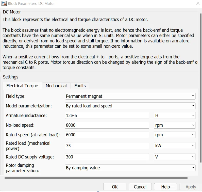
- Here we have considered a 75 kW Permanent magnet DC motor with a rated DC supply voltage of 300 V.
- Rated speed of the motor is 6000 rpm and the no load spees is 8000 rpm.
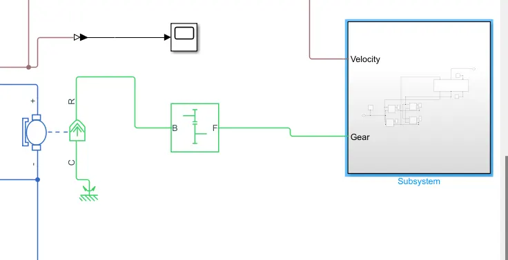
- The motor is connected to the transmission system (gear) of the vehicle.
- The motor is driven by a H-bridge motor drive and controlled PWM voltage block in averaged mode.
- In Averaged mode, the PWM port voltage divided by the PWM signal amplitude parameter defines the ratio of the on-time to the PWM period.
- Using this ratio and assumptions about the load, the block applies an average voltage to the load that achieves the correct average load current. The Simulation mode parameter value must be the same for the Controlled PWM Voltage and H-Bridge blocks.
- The arrangement is shown below:
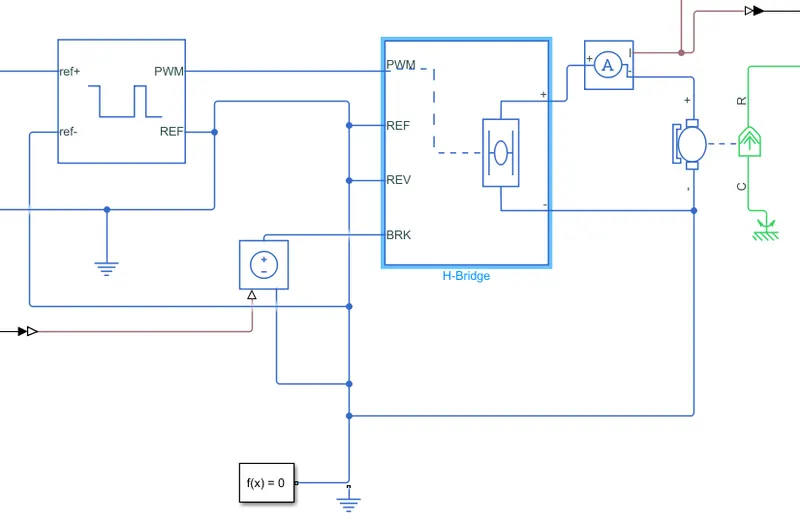
H-bridge motor drive circuit
The parameters of H-bridge is configured as shown below:
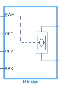
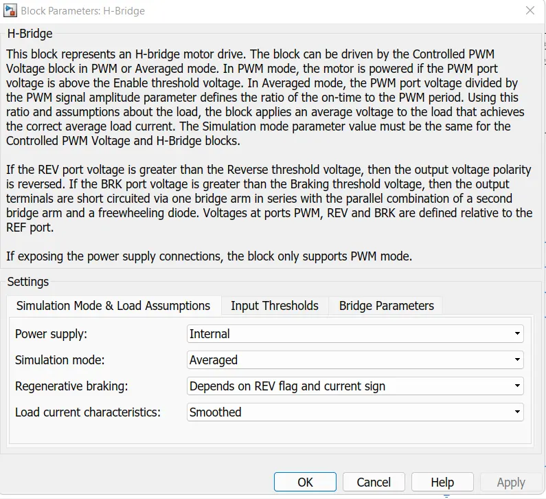
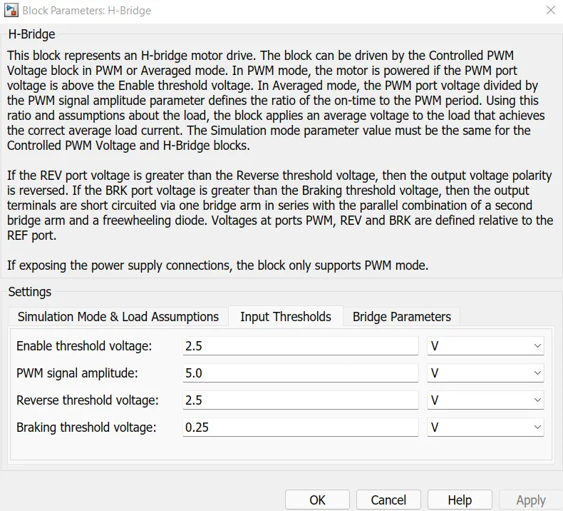
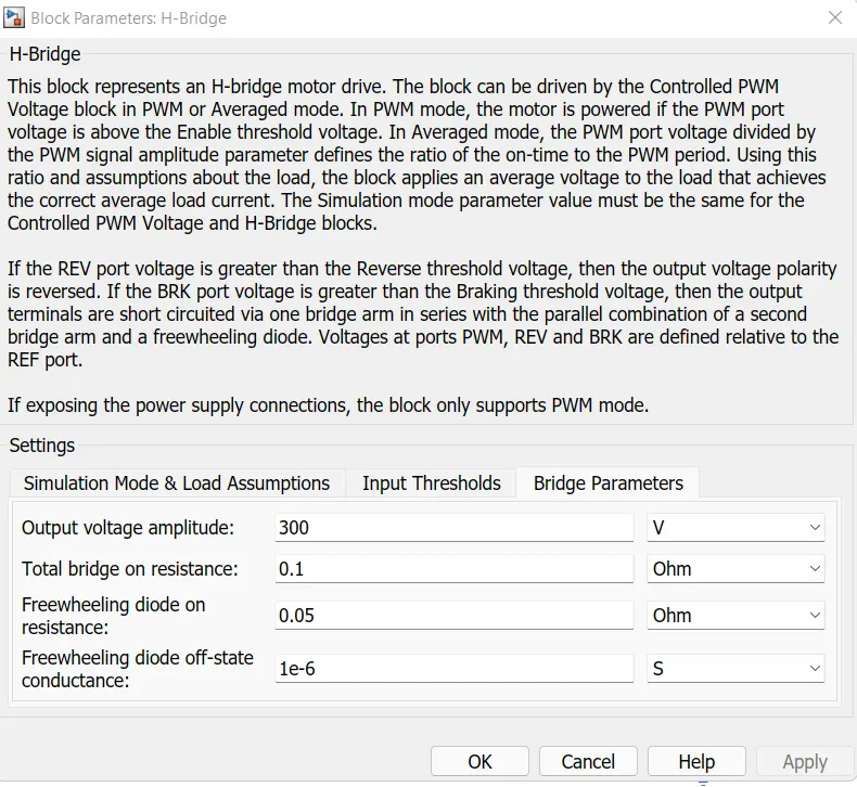
In the bridge parameters, the output voltage is set as 300 V which is the required DC voltage for permanent magnet DC motor.
Controlled PWM voltage block
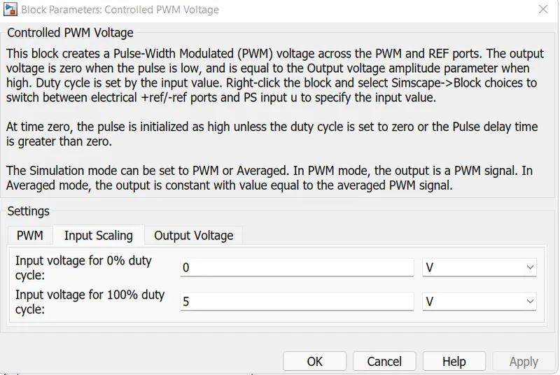
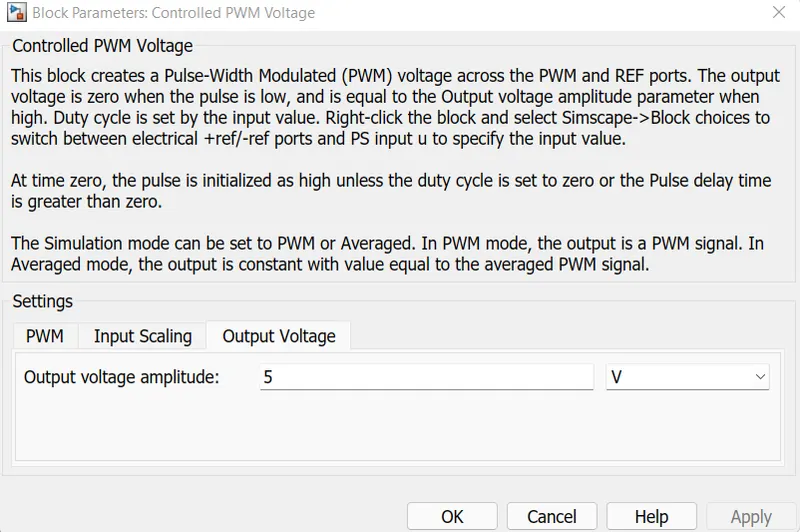
The parameters of PWM voltage control block is set as below:
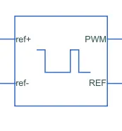
This block creates a Pulse-Width Modulated (PWM) voltage across the PWM and REF ports.
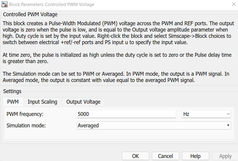
PWM frequency is set to 5000 Hz.
Longitudinal driver:
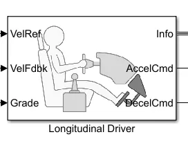
- It is a parametric longitudinal speed tracking controller in powertrain blockset for generating normalized acceleration and braking commands based on reference and feedback velocities.
- The velocity is fed back from the vehicle and the reference velocity for the longitudinal driver block is given by a drive cycle source from the power train blockset.
Drive cycle source:
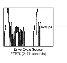
- It generates a standard or user-specified longitudinal drive cycle. The block output is the vehicle longitudinal speed.
- Here we have considered FTP-75 driving cycle which is an EPA(Environmental Protection Agency) federal test procedure for city driving cycle.
Battery Model
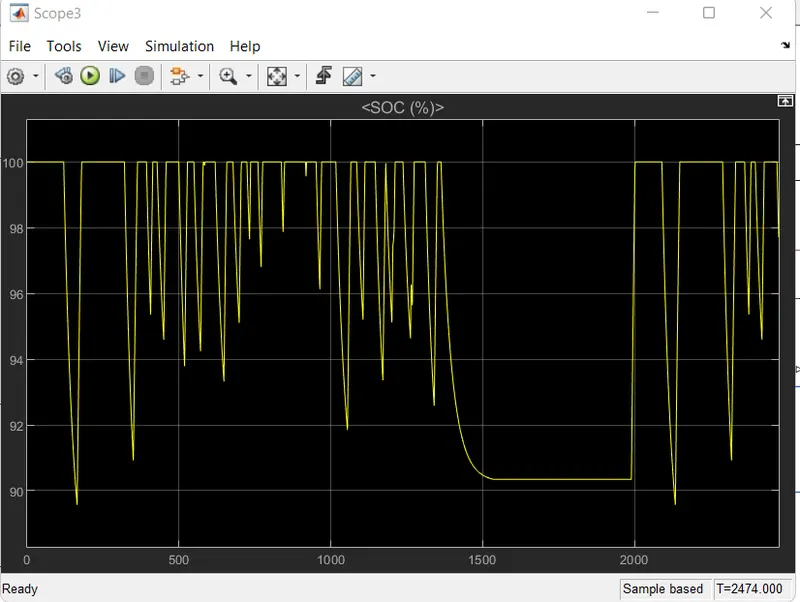
- During braking conditions, motor will be acting as a generator and it charges the battery (SOC% increases).
- During normal motoring operations, power will be consumed from the battery and SOC(%) decreases.
- Default battery model is connected to the motor through a controlled current source to analyse the performance and SOC(%), Current and voltage are plotted
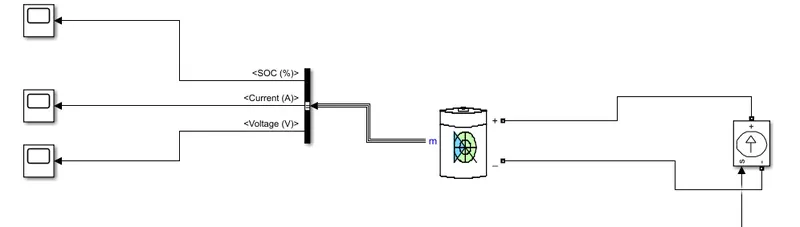
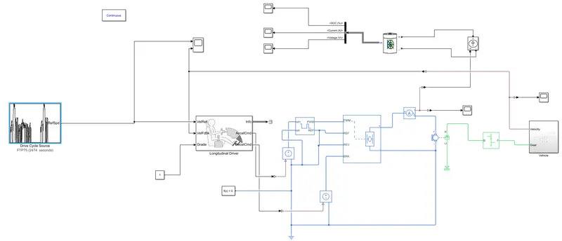
Thus the entire vehicle systems is formulated and then implemented in the form of subsystems, blocks and signals within Simulink as shown below:
Working:
- In the above model, FTP-75 driving cycle is given to the longitudinal driver block as reference velocity.
- The longitudinal driver block generates normalized acceleration and braking commands based on reference and feedback velocities.
- The controlled PWM voltage source generates the switching signals (in accordance with the output from the longitudinal driver circuit) to the H-bridge motor drive circuit which drives the motor.
- The motor gives required power for the electric vehicle so that it starts to follow the given reference driving cycle.
- The velocity of the vehicle is fed back as one of the inputs to the longitudinal driver block.
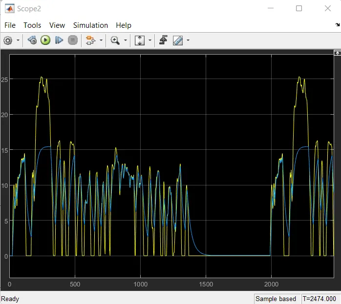
The comparison of velocity of the vehicle and how it follows the reference driving cycle is as shown below:
Yellow colour indicates the driving cycle velocity and blue colour indicates the velocity of the vehicle.
The variation of battery SOC with the given drive cycle is as shown below:
The plot of variation of battery voltage and current is as shown below:
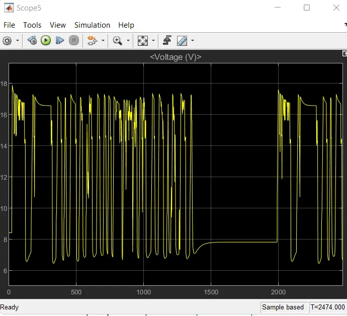
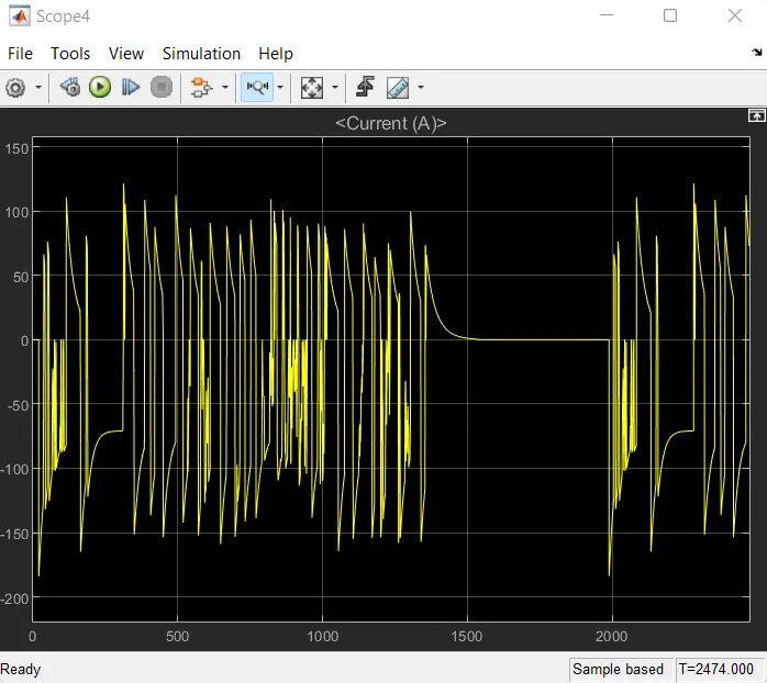
From the graphs of voltage and current, it is clear that Battery voltage is always positive and battery current reverses during braking.
When battery voltage is positive and current is positive ----> Battery discharges (Motoring mode)
When battery voltage is positive and current is negative ----> Battery charges (Braking mode)
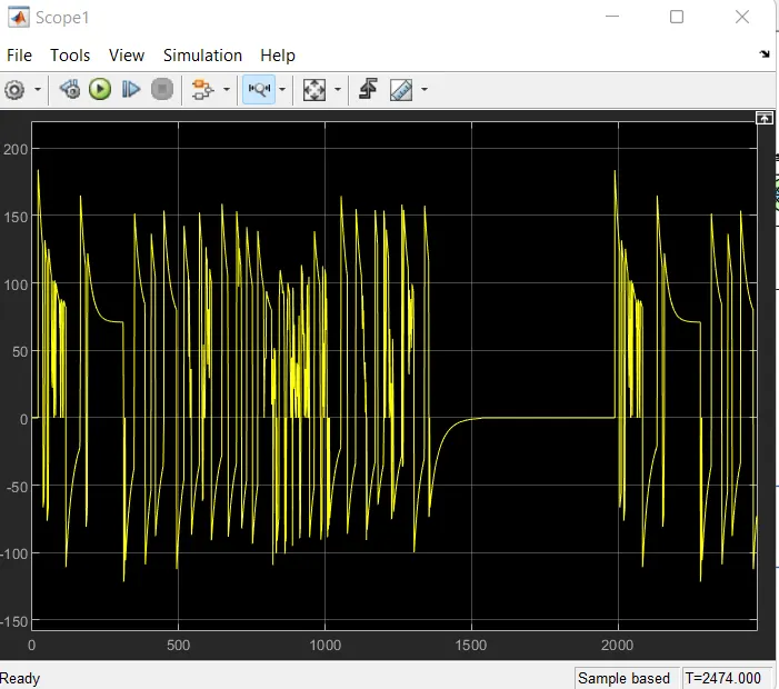
The corresponding variations in motor current is plotted below: