Final Project: Design of an Electric Vehicle
Create a MATLAB model of electric car which uses a battery and a DC motor. Choose suitable blocks from Powertrain block set. Prepare a report about your model including following:
Objectives:
1. System level configurations
2. Model parameters
3. Results
4. Conclusion
System level configurations
- Block Diagram
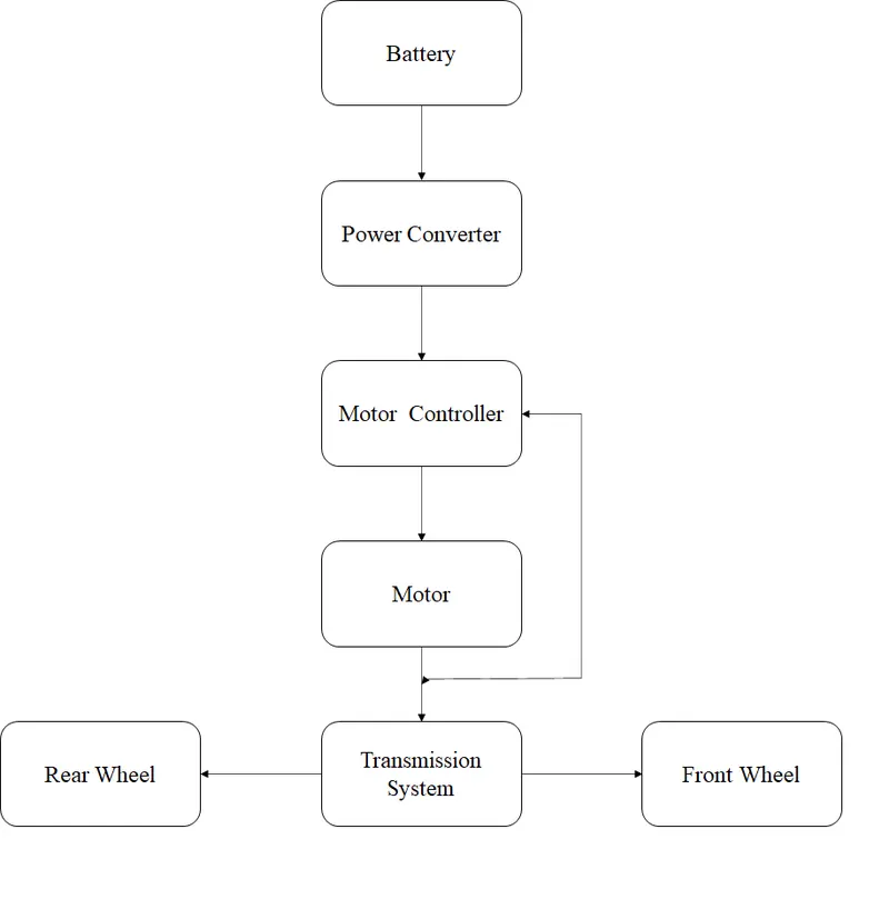
- It is the diagrammatic representation of the Electric powertrain.
- Model
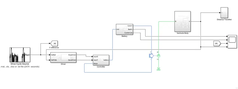
- This model represents the Electric drive train of an Electric Vechicle.
Model parameters
- Drive Cycle
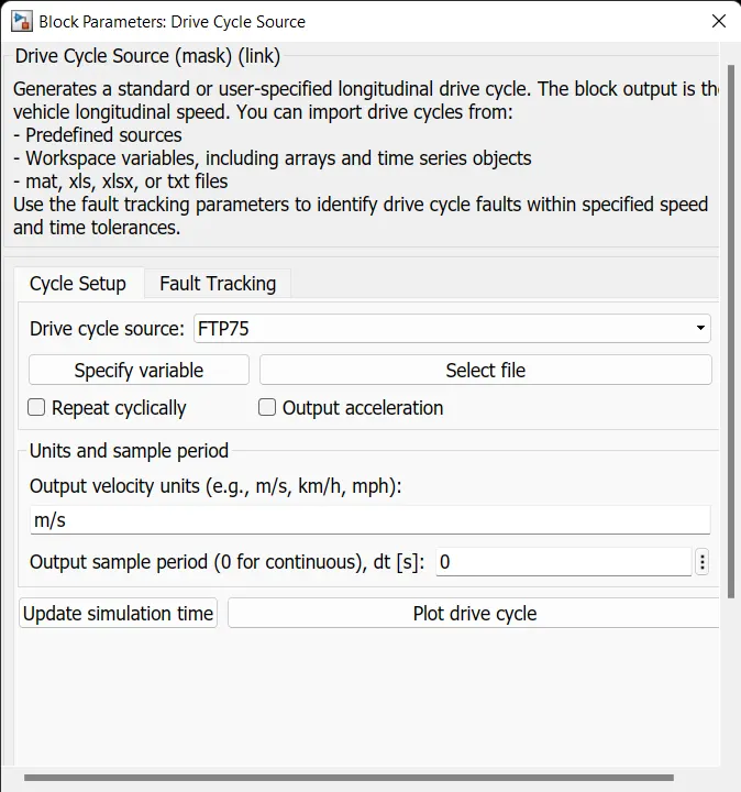
- The Drive cycle block consists of n number of drive cycle .
- The FTP75 Cycle is choosen for our simulation.
- We acn also use our own drive cycle which can be imported in ".mat, .xls, .xlsx or .txt " file format.
- It is the reference vehicle speed for our simulation.
- The output velocity is mentioned in m/sec .
- The Drive cycle run time is 2474 seconds.
- Fault tracking
- It is disabled for our simulation.
- We can detect the error values (i.e The feedback is added to the block) .
- We can also stop the simulation when the error value exists our range.
- Driver Block
- It is the subblock which consists of Longitudinal driver block
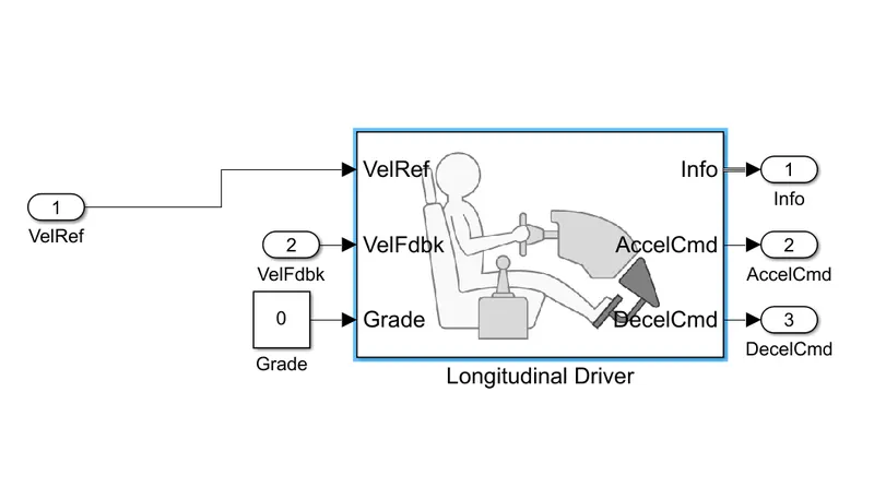
- It has 3 input variables
- Velref -----> It is drive cycle signal.
- Velref -----> The actual velocity of the vechicle is given as feedback signal.
- Grade -----> The grade ability of the vechicle is given by the help of the constant block.
- It has three Output
- AccelCmd -----> It is acceleration signal .
- DecelCmd -----> It is the deacceleration signal .
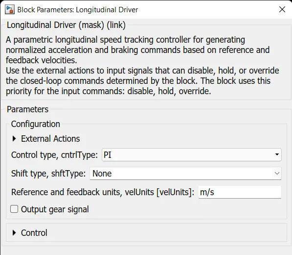
- It is the PI controller block where the input velocity is compared with the output velocity.
- It acts like a driver whose controlling the vechicle .
- The PI controller tries to achieve the input velocity (refference velocity).
- Controller Block
- It is the Subblock which consists of power converters .
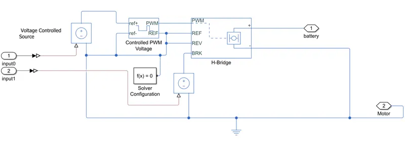
- Simulink-PS Converter
- Controlled PWM Voltage.
- H Bridge.
- Voltage Controlled Source
- Solver Configuration.
- Voltage Controlled source
- The block represents an ideal voltage source that is powerful enough to maintain the specified voltage at its output regardless of the current passing through it.
- The output voltage is V = Vs, where Vs is the numerical value presented at the physical signal port.
- Controlled PWM Voltage
- This block creates the Pulse Width Modulated (PWM) Voltage .
- The input ports are ref+ and ref-.
- The output ports are PWM and Ref.
- By the help of this block we can set the duty cycle .
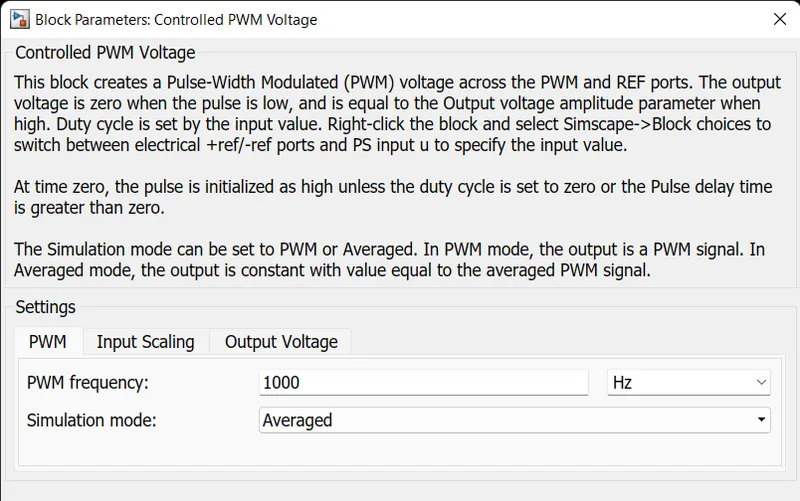
- For our simulation PWM switch frequency is 1000 Hz and the average mode is used.
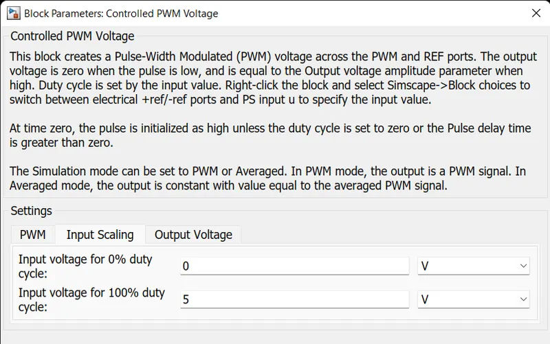
- From the Input scaling tab,We can set the input voltage .
- For our simulation the minimum input voltage is 0 V and the maximum input voltage is 5 V.
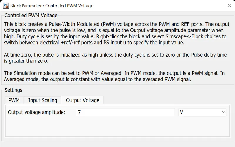
- From the output voltage tab,We can the set output voltage .
- For our simulation the minimum output voltage is 0 V and the maximum output voltage is 7 V.
- The duty cycle is setted in the ratio of boost manner.
- H-Bridge
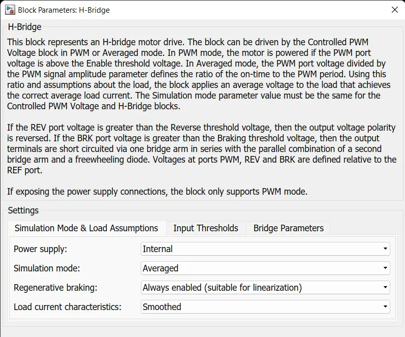
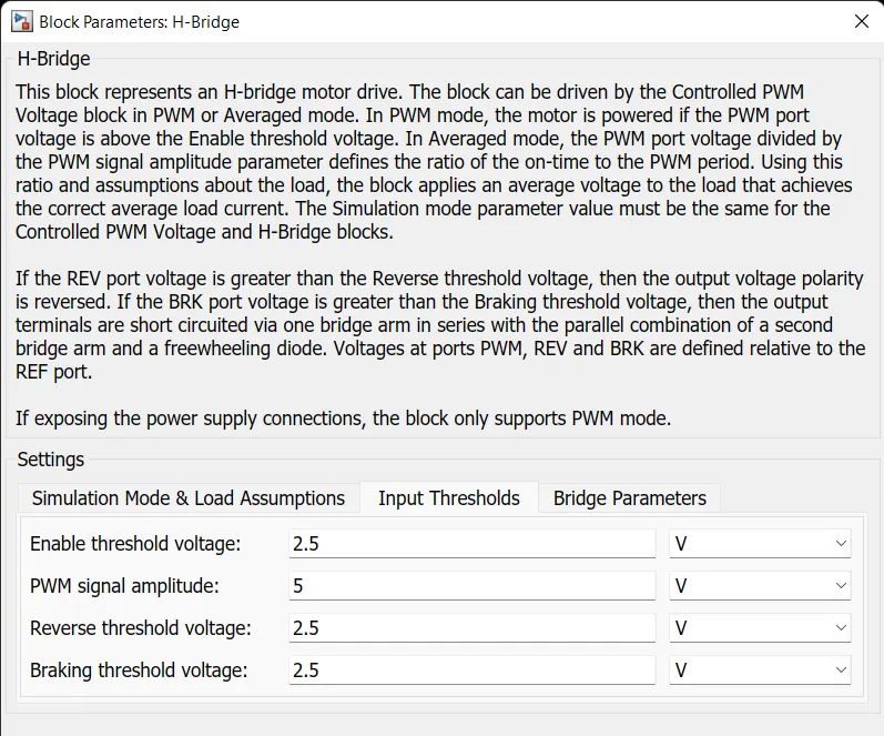
- This block represents an H-bridge motor drive.
- The block can be driven by the Controlled PWM Voltage block in PWM or Averaged mode.
- By the help of H bridge the motor can be run in both forward and reverse motoring operation.
- The H bridge will control both battery and the motor.
- It consists of 4 inputs .
- PWM -----> The output of the Controlled PWM voltage block is connected to it.
- Ref -------> It is the refference port which is also connected from the Controlled PWM voltage block.
- Rev -------> The poet stands for reverse motor operation.
- Brk --------> The port stands for Braking of motor opertion.
- For the Rev port is connected from the acceleration command from the driver block.
- For the Brk port is connected from the Deacceleration command from the driver block.
- It consists of two outputs.
- + ve ----> is connected for the battery controll.
- - ve is connected for the motor controll.
- Simulation and load Assumption
- Input Thresholds
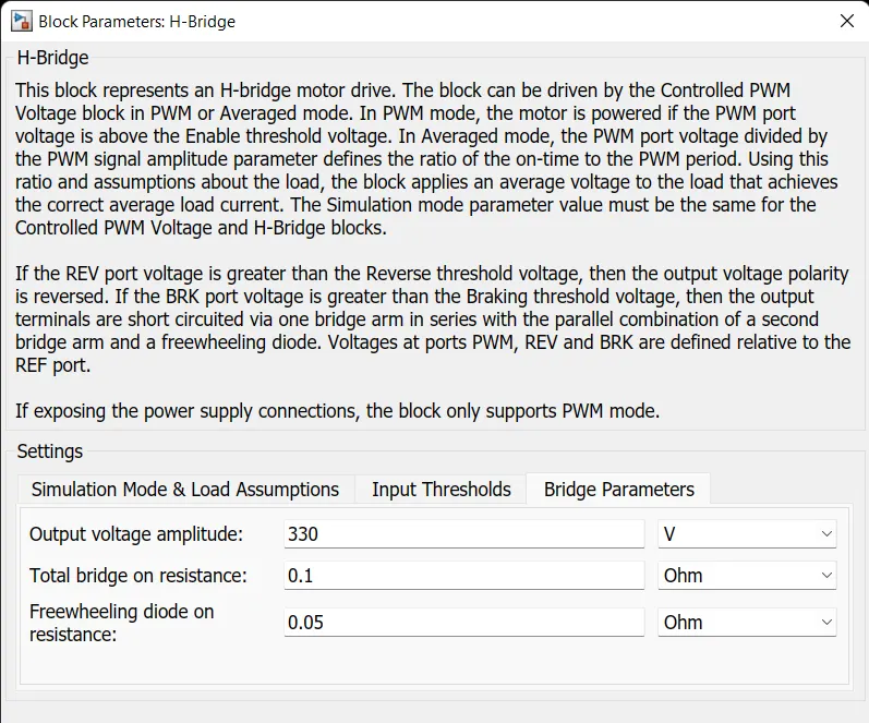
- Bridge Parameters
- To run the motor 330 V is setted as output voltage.
- The remaining parameters are setteda s default values.
- Solver Configuration
- Each physical network represented by a connected Simscape block diagram requires solver settings information for simulation.
- Simulink-PS Converter
- Converts the Simulink input signal to a Physical Signal.
- Here the two blocks are used.
- The Simulink input signal is Acceleration command and deacceleration command.
- The Physical signal is controlled voltage source.
- Electrical Rerference
- The Electrical Reference block represents an electrical ground.
- Electrical conserving ports of all the blocks that are directly connected to ground must be connected to an Electrical Reference block.
- A model with electrical elements must contain at least one Electrical Reference block.
- Battery
- It is the Subblock which consists of
- Battery.
- Soc unit.
- PS Simulink block.
- Controlled Current Source.
- Current sensor.
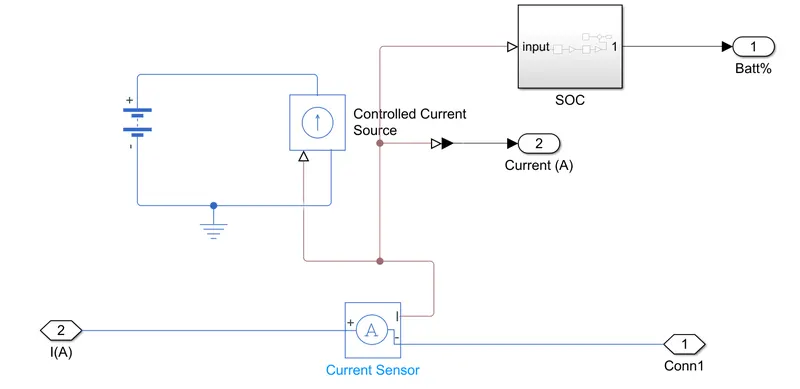
- Battery
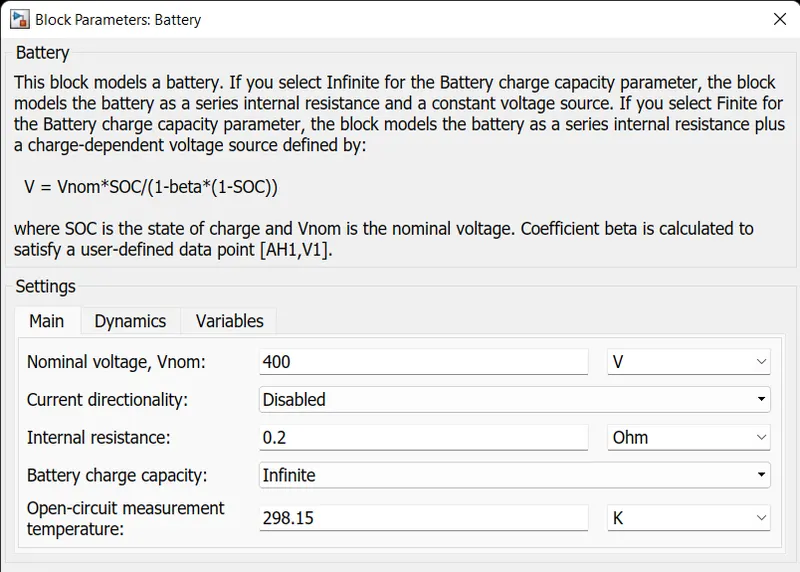
- For our simulation we have used 400 v battery.
- The dynamics and variables are set as default values.
- Controlled Current Source
- It is connected to the Battery.
- The Controlled Current Source block represents an ideal current source that is powerful enough to maintain the specified current through it regardless of the voltage across the source.
- The output current is I = Is, where Is is the numerical value presented at the physical signal port.
- Current Sensor
- It has 3 ports
- + ve ----->It is connected to the +ve of the H bridge.
- - ve -----> it is connected to the +ve of the motor.
- I ----------> It is connected to the Controlled current source.
- It has 3 ports
- PS-Simulink Converter
- Converts the input Physical Signal to a Simulink output signal.
- The Physical siganl is output of the current siganl.
- The Simulink signal is connected to the scope.
- SOC
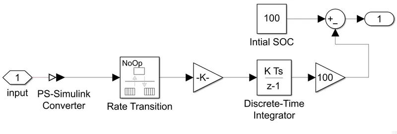
- PS-Simulink Converter
- Converts the input Physical Signal to a Simulink output signal.
- The Physical siganl is output of the current sensor I.
- The Simulink signal is connected to the Rate Transition.
- Rate Transition
- The Rate Transition block transfers data from the output of a block operating at one rate to the input of a block operating at a different rate.
- The values are setted as default.
- Gain
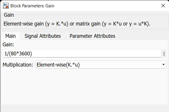
- By multiplying with (1/80*3600) we can find the nominal battery capacity of the battery
- Discrete Time Integrator
- Use the Discrete-Time Integrator block in place of the Integrator block to create a purely discrete model.
- It is used to convert the dicrete to integrated signals.
- The values are setted as default values.
- Constant
- Here the 100 represents the battery intial charge percentage.
- Summer
- To find the current battery percentage The inital SOC and Discrete Time integrator are subracted .
- It is the Subblock which consists of
- DC Motor
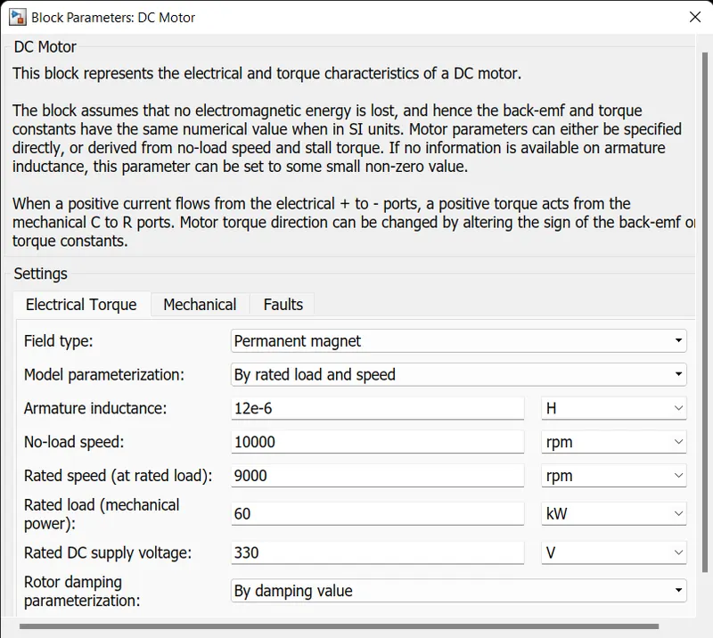
- For our simulation the DC Permanent magnet motor is used.
- It has two inpiut and two outports
- The input ports are Electrical (+Ve & - Ve)
- The + ve is connected from the - ve of the current sensor.
- The - ve is connected from the - ve of the voltage sensor.
- The output ports arer Mechanical (C & R)
- C is connected to the Mechanical rotational refference.
- R is conected to the simple gear block in Vechicle body sub block.
- Mechanical and Faults are setted as default values.
- The input ports are Electrical (+Ve & - Ve)
- Vehicle Body
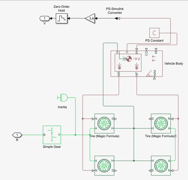
- It is the sub block which consists of
- Simple Gear
- Tire (Magic Formulae) 4
- Interia
- Vechicle Body
- PS-Simulink Converter
- Gain
- Zero Order Hold
- Simple Gear
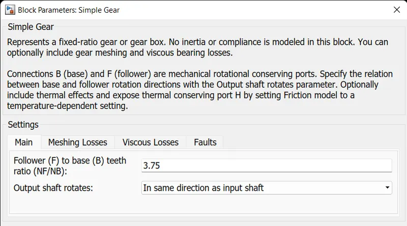
- It has two ports
- B port
- It is connected from the R port of the DC motor.
- F port
- It is connected to the A port of the Tire
- B port
- The gear ratio is setted as 3.75 for the optimistic value for our simulation.
- The meshing losses is setted as 0.89 efficiency.
- The viscous and faults tab are setted as default values.
- Inertia
- The block represents an ideal mechanical rotational inertia.
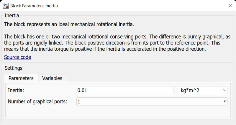
- The values are setted as default.
- It is connected between Simple gear and tire
- Tire
- For our simulation we have selected the Tire (magic formulae).
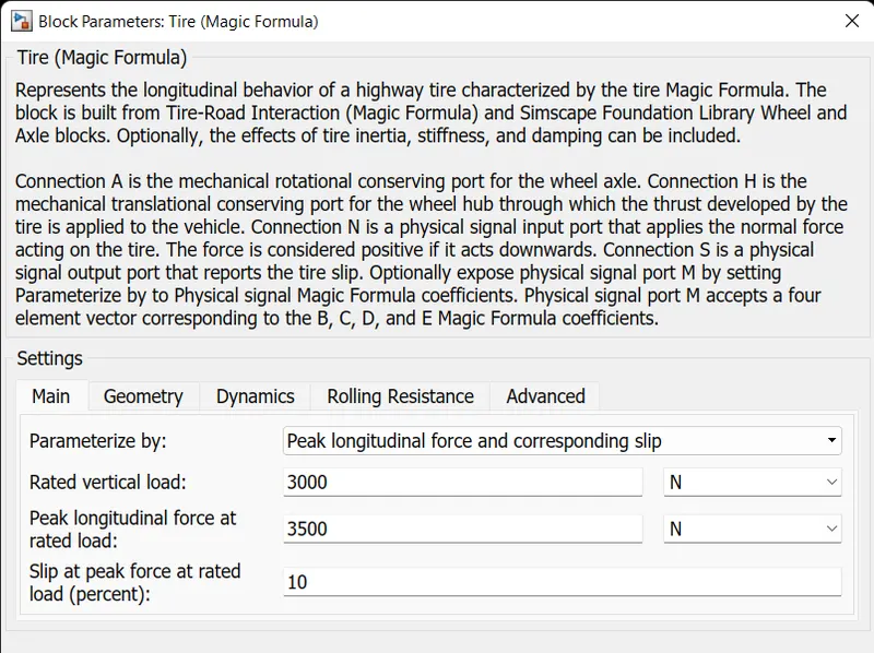
- Represents the longitudinal behavior of a highway tire characterized by the tire Magic Formula.
- The block is built from Tire-Road Interaction (Magic Formula) and Simscape Foundation Library Wheel and Axle blocks.
- Optionally, the effects of tire inertia, stiffness, and damping can be included.
- It has four ports
- N (Normal Force) Port
- Physical signal input port associated with the normal force acting on the tire.
- The normal force is positive if it acts downward on the tire, pressing it against the pavement
- H (Hub) Port
- Mechanical translational port associated with the wheel hub that transmits the thrust generated by the tire to the remainder of the vehicle.
- A (Axle) Port
- Mechanical rotational port associated with the axle that the tire sits on.
- S (Slip) Port
- Physical signal output port associated with the relative slip between the tire and road.
- N (Normal Force) Port
- The 4 tyres are used
- 2 tyres are connected to the rear axle.
- 2 tyre are connected to the front axle.
- The geometry, dynamics , advanced are setteds as default values.
- Rolling resistance is enabled.
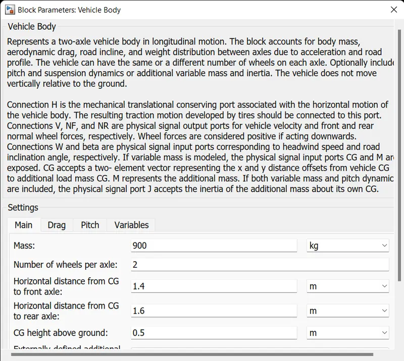
- Vehicle Body
- Represents a two-axle vehicle body in longitudinal motion.
- The block accounts for body mass, aerodynamic drag, road incline, and weight distribution between axles due to acceleration and road profile.
- PS-Simulink Converter
- Converts the input Physical Signal to a Simulink output signal.
- The Physical siganl is output of the V (velocity experienced by the vechicle).
- The Simulink signal is connected to the Gain.
- Gain
- The m/sec is converted to Km/hr by multiplying the 3.6 with it.
- Zero Hold order
- The Zero-Order Hold block holds its input for the sample period you specify.
- If the input is a vector, the block holds all elements of the vector for the same sample period.
- A setting of
-1means the block inherits the Sample time.
- Distance Travelled
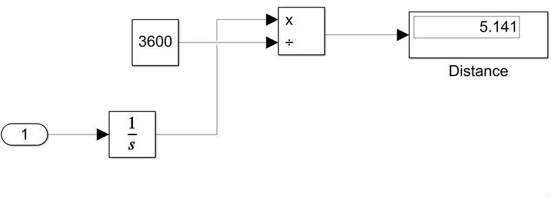
- It is the subblock which is used for calculating the distance travelled by the vechicle.
- By integrating the Velocity of the vechicle and multiplying with 3600 we can find the ditance traveled by the vehicle in Km.
- Result
-
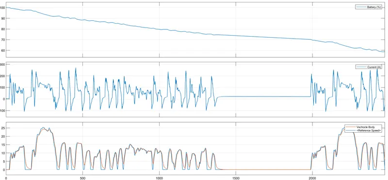
- Reffernce speed Vs Vechice body
- From the plot we can find there is the difference between the refference speed and the vechicle speed.
- The refference speed is the duty cycle which runs for 2474 seconds
- The PI controller tries to achieve the same speed as reference speed.
- By varrying the gear ratio and the duty cycle we can achieve the vehicle speed close to refferernce speed.
- During the downfall of the speed we can notice the regenerative braking is applied so the vechicle takes some time to reaches the minimum speed.
- Current (A)
- It is the current entering through the armature winding.
- When the speed is maximum we can see that the motor utilizing the maximum current (positive flow of current)of 250 A.
- When the regerative braking is applied we can see the motor acts as an generator and supplies the current to the battery (negative flow of current).
- We regerative current is not same as maximum current due to the battery and powert converters limitations.
- Battery (%)
- For the total run time of 2474 seconds the battery state os discharge is 61%.
- We camn also see that the battery gets charged when the motor operates in regerative mode.
- Distance
- The total distance travelled by the vechicle is 5.141 Km in 2474 seconds.
-
- Conclusion
- The EV model is attached as "Project".
- The simulation is done by the matlab software.
- The Drive cycle used is FTP75 which has the runtime of 2474 seconds.
- The working of the model is explined in detailed.
- From the simulation we can understand the basic working of the EV model with the losses associated with it.