Final Project: Design of an Electric Vehicle
Objective:
To create a MATLAB model of electric car which uses a battery and a DC motor. Choose suitable blocks from Powertrain block set. Prepare a report about your model including following
1. System level configurations
2. Model parameters
3. Results
4. Conclusion
Electric Cars:
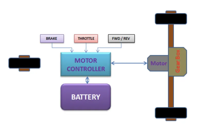
All-electric vehicles (EVs), also referred to as battery electric vehicles, have an electric motor instead of an internal combustion engine. The vehicle uses a large traction battery pack to power the electric motor and must be plugged in to a wall outlet or charging equipment, also called electric vehicle supply equipment (EVSE). Because it runs on electricity, the vehicle emits no exhaust from a tailpipe and does not contain the typical liquid fuel components, such as a fuel pump, fuel line, or fuel tank.
Key Components of an All-Electric Car
- Simulink have a build in block for vehicle body in simscape -> Driveline -> tiers and vehicles.
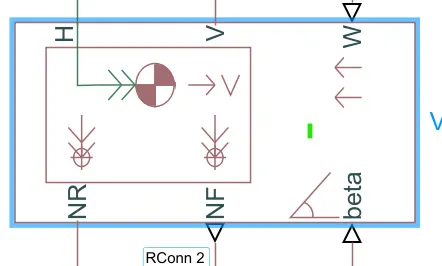
- H - Hub of the vehicle / chasis
- V - vehicle velocity
- w - wind effect
- NR - rear force
- Nf- nominal force for front wheel
- Beta- terrain inclination angle
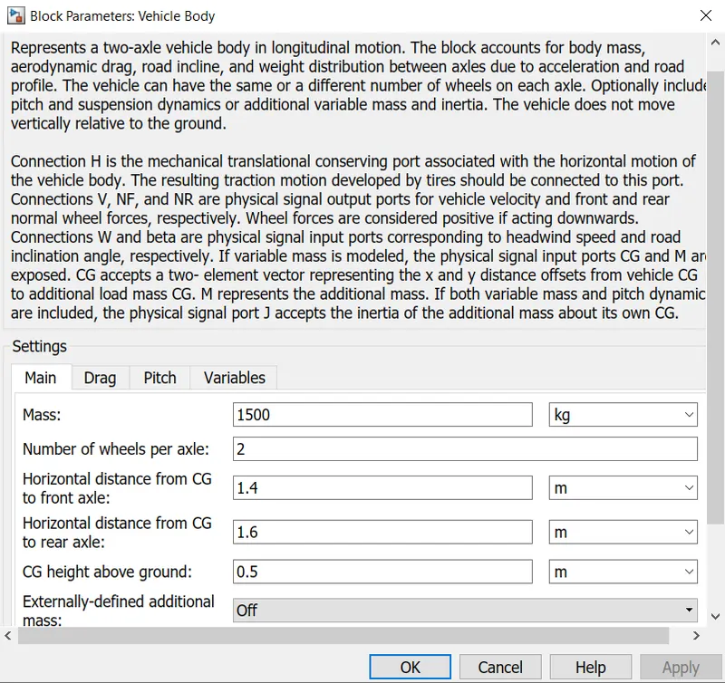
- if you want to now more about the block clic the help icon.
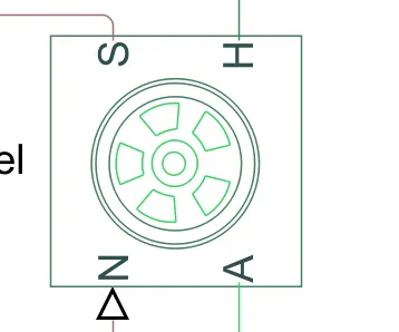
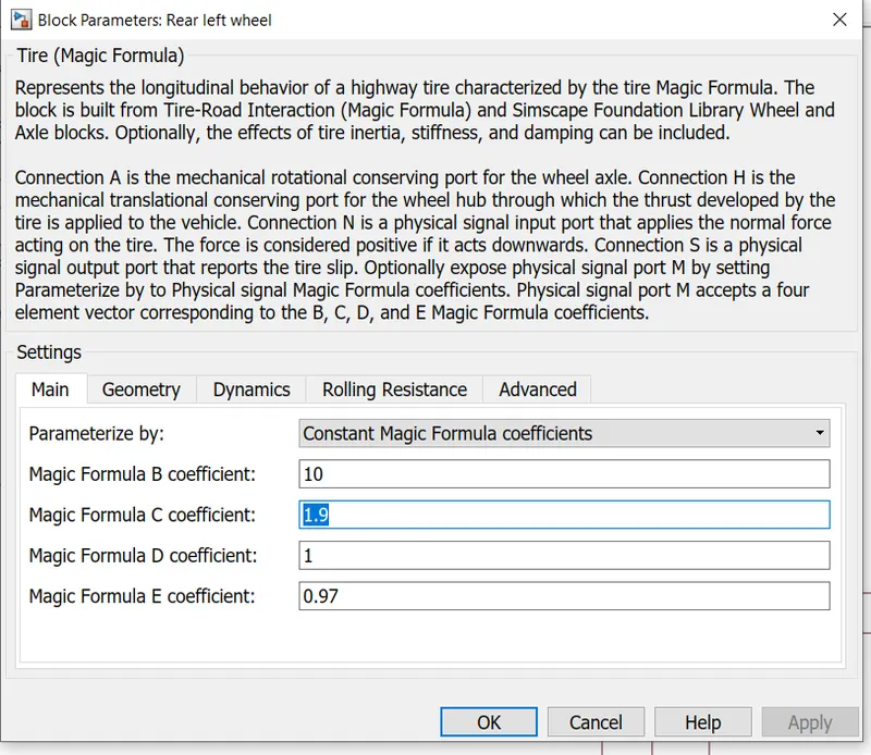
- Matlab has a buid in block for modelling tyre and i use magic formula tyre bloc to model the tyre.
- It has four coefficients namely B,C,D,E.
- All other parameters are leave as default.
- The blok has four connections,they are
- N -> Normal force input
- A -> axel
- S -> tyre slip with respect to ground due to the force
- H -> hub of the wheel
Connection between tyres and vehicle body:
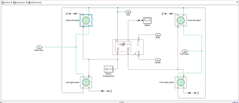
- Now the vehicle body modeling is complited.
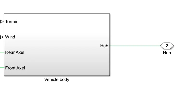
- The hub port gives the vehicle linear movement
- The terrain and wind port are used for modelling the road gradient and wind effect to the car.
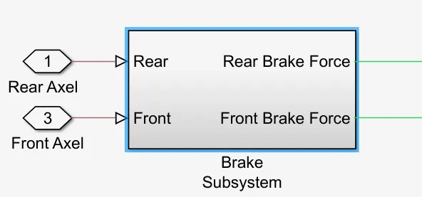
- The real and front axel are used to apply the driving and brake forces to the rear and front axel respectively.
The Brake Unit:
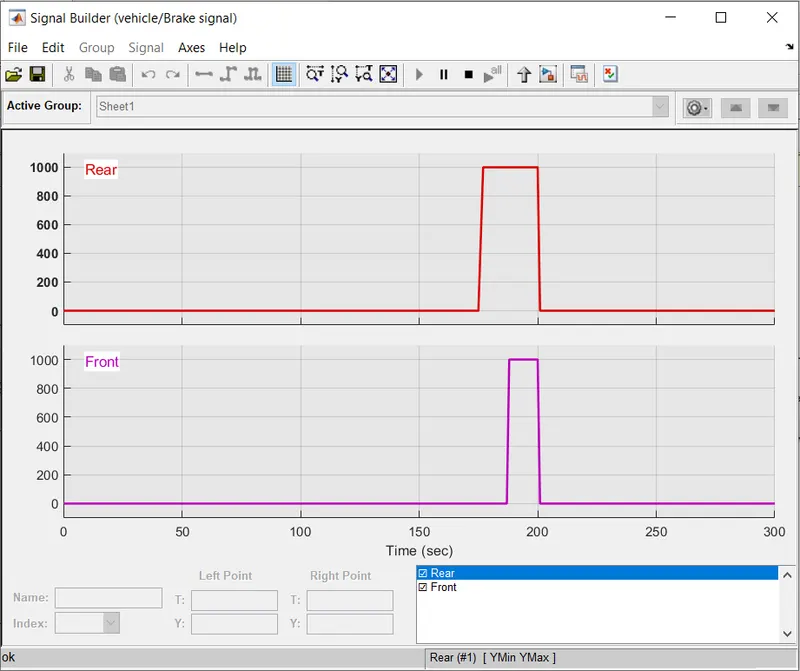
- In order to model the brakes for the vehicle we use the disk brake model from the simscape mechanical library
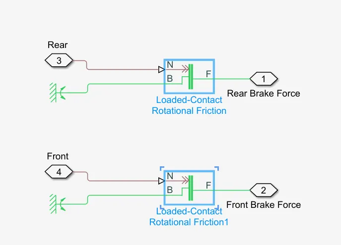
- It has 3 terminals N- >input brake force
- B-> mechanical reference
- F-> Output brake force.
Gear subsystem:
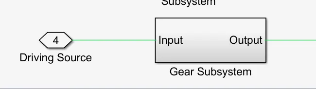
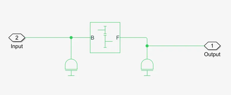
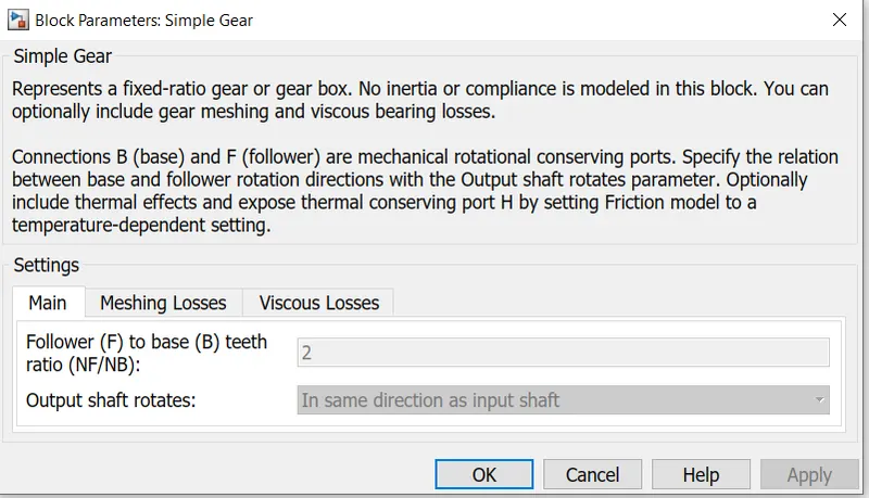
- Simscape library has a simple gear block for modelling the gears for a vehicle.
The Driving Source:
For an electric vehicle the source for the propulsion is The motor powered by Battery
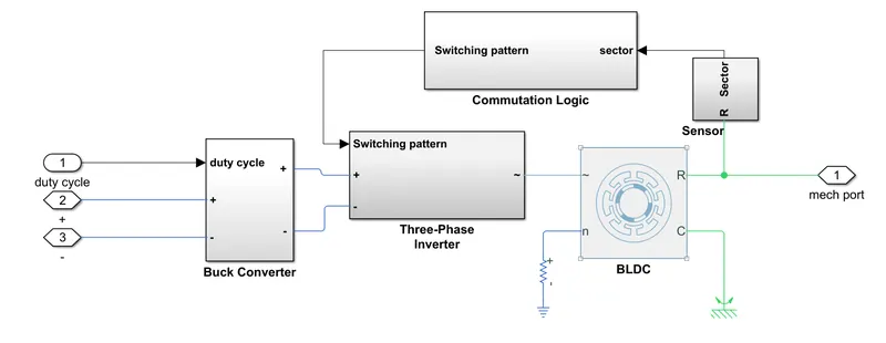
The subsystem for The Motor and controller block are
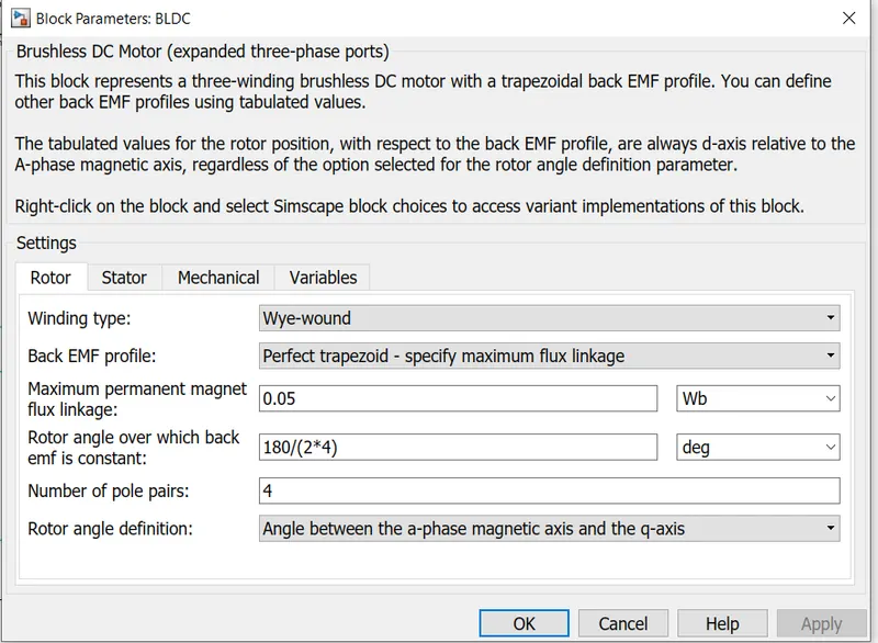
- Motor (BLDC Motor)
- Invereter Block (To perform commutation for Bldc motor)
- Buck converter (For speed controlling the motor)
- Sensor( To find the position of rotor)
- Comutation Logic( To perform commutation electronically)
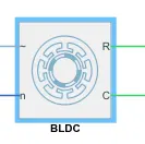
BLDC Motor:
Battery:
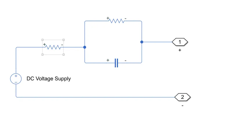
Fig: Battery individual cell
cell nominal voltage: 12v
series Resistance : 0.001 ohm
Time constant R = 0.0005 ohm
C = 5000 F
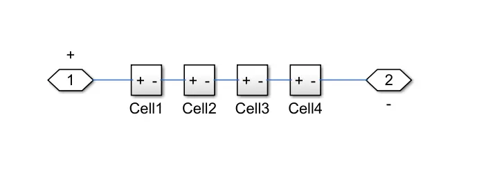
Fig: Battery Subsystem
Buck Converter/Speed Controller:
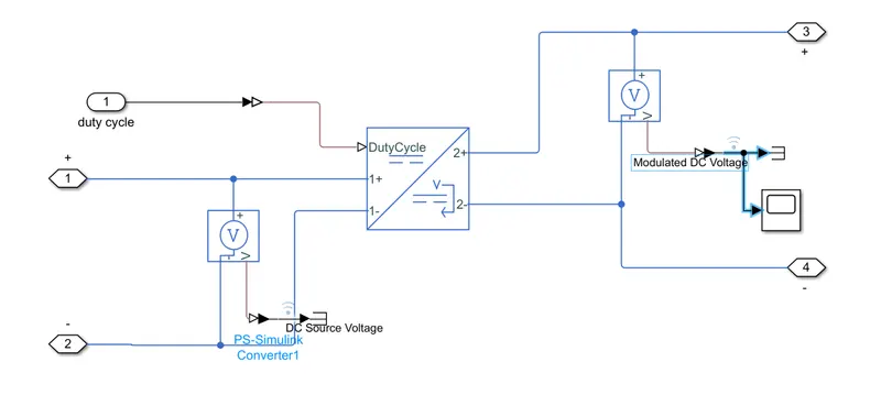
Buck converter
- The buck converter is to regulate the Batter voltage(48v) interms of duty cycle(0 to 1)
Inverter:
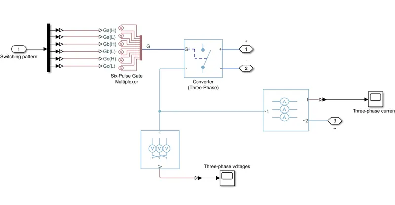
fig: Inverter subsystem
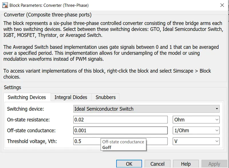
Fig: Inverter Parameter Setting
Sensor:
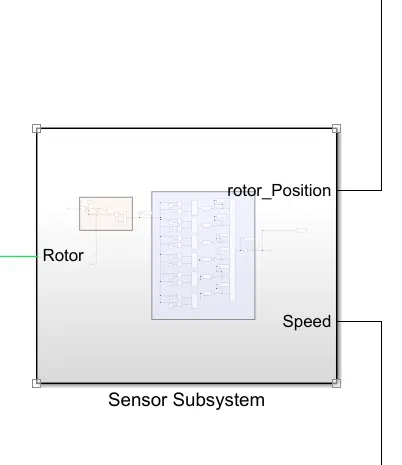
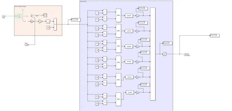
Fig: Sensing Rotor position
- To perform the commutation we need to know the position of the rotor
Commutation Logic:
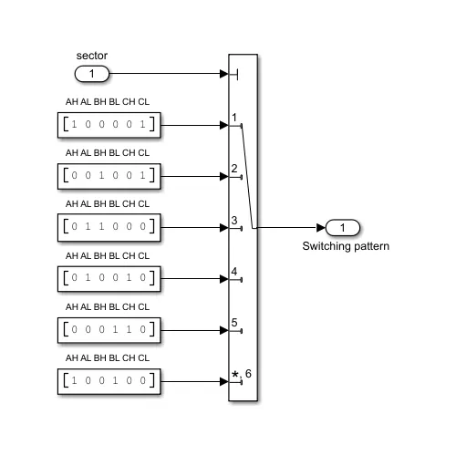
Fig : Switching Pattern
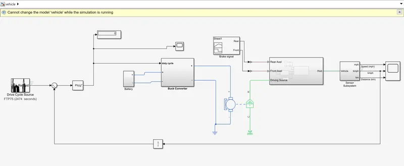
Closed Loop control system:
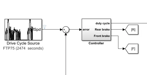
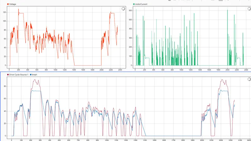
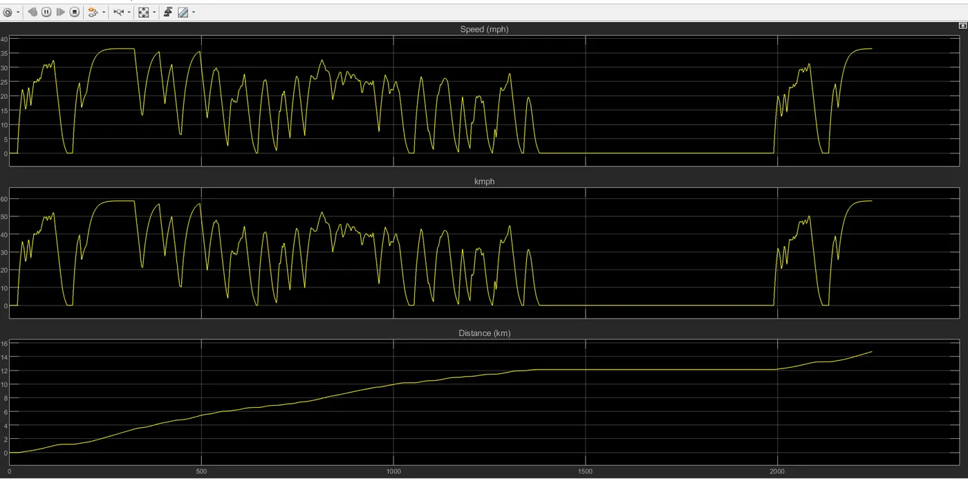
Result-1:
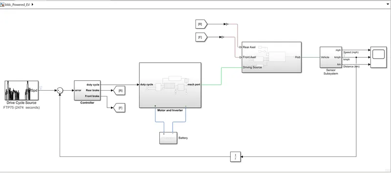
BLDC powered DC EV:
MODEL
OUTPUT:
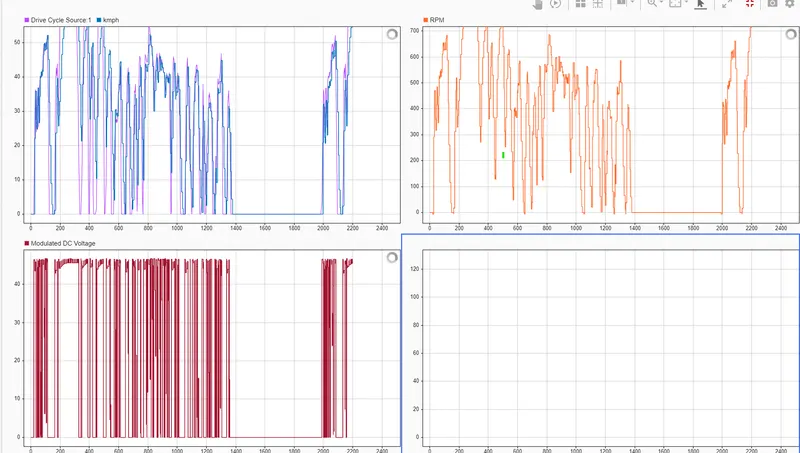
Result-2:
DC powered EV
Output: