Project 1 (Mini Project on Vehicle Direction Detection
AIM:
To build a simulink model which will detect the direction of an vehicle.Then the detected direction is compared against camera input signal and the results are shown.
OBJECTIVE:
- Development of MATLAB Simulink model as per requirement.
- Tag the requirements to the simulink model; tagging requirement 1 & requirement 2 to their corresponding subsystems is fine.
- MBD compliant changes, Data Dictionary creation & code generation is added advantage, and that is not scope of this project.
- If choosing code generation, Storage class for Input signals: ImportedExtern; Storage class for Output signal: Export to File; Storage class for local signals: localizable; Storage class for calibration signals: Const.
- Choose sample time for all signals as 0.01s
MODEL DEVELOPEMENT:
REQUIREMENT1:
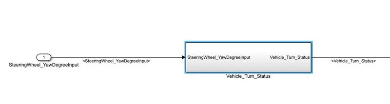
- A subsystem to detect the direction of vehicle.
- INPUT is SteeringWheel_YawDegreeInput and the OUTPUT is Vehicle_Turn_Status.
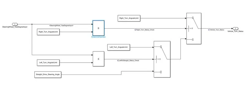
- The input is compared with the 3 pre defined caliberation value like Right_Turn_AngularLimit,Left_Turn_AngularLimit and Straight_Drive_Steering_Angle.
- With the help of switch block and relational operator block the logic is performed and respective output Vehicle_Turn_Status is taken out.The logic is shown below.
REQIREMENT2:
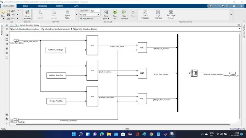
- A subsytem to compare the Camera input and the vehicle_Turn_Status to check wheather the vehicle is in right direction.
- INPUTS are CameraInput_RoadSign and vehicle_Turn_Status,The OUTPUT is vehicle_Direction_indicator.
- The logic is performed bu comapring thr Vehicle_Turn_Status with the pre defined caliberation value like RightTurn_RoadSign,LeftTurn_RoadSign and Straight_RoadSign.
- Then each of these output is compared with CameraInput_RoadSign using logical operators.The logic is shown below.
DATA DICTIONARY CREATION:
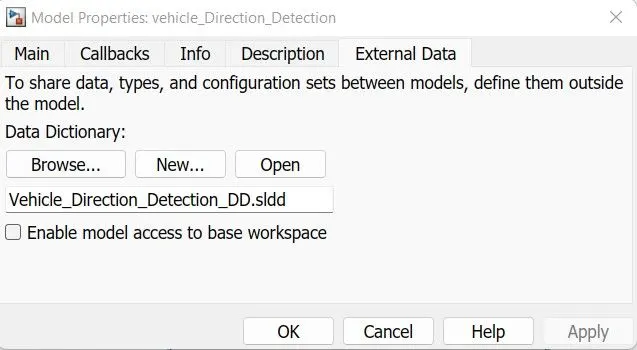
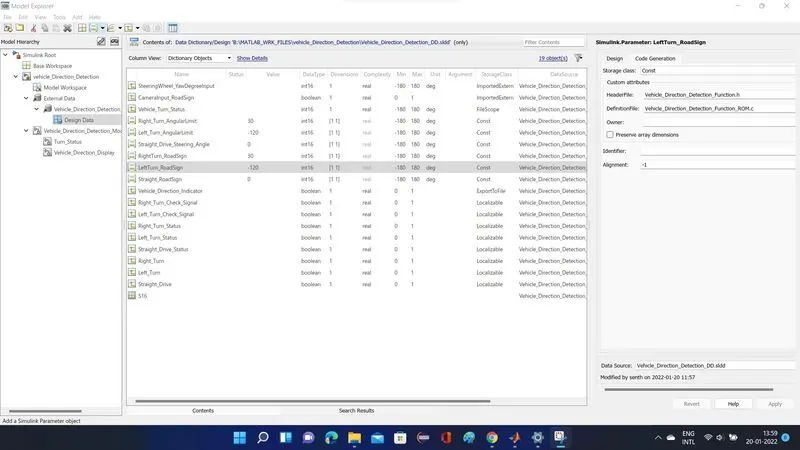
- A new SLDD is created as Vehicle_Direction_Detection_DD and it is linked with the model.
- All the simulink input/output signal calib_parameters and local signals which are used in model are created and their respective storage class are given as per requirement.
MODEL CONFIGURATION SETTING:
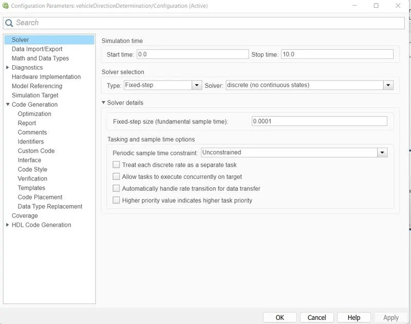
- The basic configuration setting is shown below
REQUIREMENTS TAGGING:
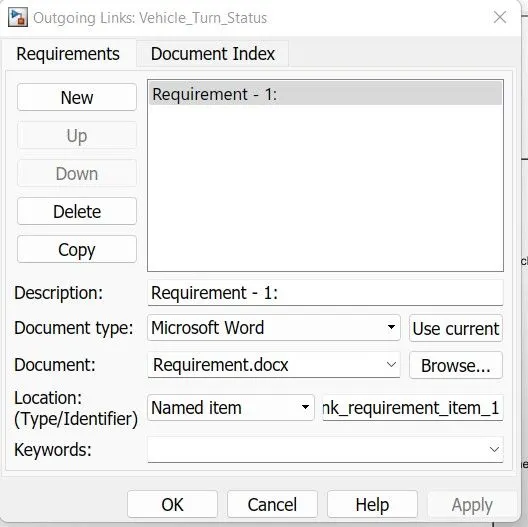
- Right click the subsystem/block you want to tag for the requirement tagging select the requirement and select the tagging with word document.
- For this we want the requirement as a word/exel/in matlab model file.
- It will create a link between the subsystem/block with the document in .slxc format.
- The linked .slxc is attached below.
CODE GENERATION:
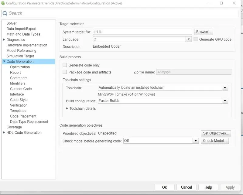
- The code generation setting is shown above
- the generated code main c code is shown below.
*
* File: vehicleDirectionDetermination.c
*
* Code generated for Simulink model 'vehicleDirectionDetermination'.
*
* Model version : 1.2
* Simulink Coder version : 9.5 (R2021a) 14-Nov-2020
* C/C++ source code generated on : Tue Jan 25 15:07:08 2022
*
* Target selection: ert.tlc
* Embedded hardware selection: Intel->x86-64 (Windows64)
* Code generation objectives: Unspecified
* Validation result: Not run
*/
#include "vehicleDirectionDetermination.h"
#include "vehicleDirectionDetermination_private.h"
/* Real-time model */
static RT_MODEL_vehicleDirectionDete_T vehicleDirectionDeterminatio_M_;
RT_MODEL_vehicleDirectionDete_T *const vehicleDirectionDeterminatio_M =
&vehicleDirectionDeterminatio_M_;
static void rate_scheduler(void);
/*
* This function updates active task flag for each subrate.
* The function is called at model base rate, hence the
* generated code self-manages all its subrates.
*/
static void rate_scheduler(void)
{
/* Compute which subrates run during the next base time step. Subrates
* are an integer multiple of the base rate counter. Therefore, the subtask
* counter is reset when it reaches its limit (zero means run).
*/
(vehicleDirectionDeterminatio_M->Timing.TaskCounters.TID[1])++;
if ((vehicleDirectionDeterminatio_M->Timing.TaskCounters.TID[1]) > 99) {/* Sample time: [0.01s, 0.0s] */
vehicleDirectionDeterminatio_M->Timing.TaskCounters.TID[1] = 0;
}
}
/* Model step function */
void vehicleDirectionDetermination_step(void)
{
/* local block i/o variables */
int16_T Vehicle_Turn_Status;
boolean_T Right_Turn_Status_Check;
boolean_T LeftOrStraight_Status_Check;
boolean_T Right_Turn_Status;
boolean_T Right_Turn_Indicator;
boolean_T Left_Turn_Status;
boolean_T Left_Turn_Indicator;
boolean_T Straight_Drive_Status;
boolean_T Straight_Drive_Indicator;
if (vehicleDirectionDeterminatio_M->Timing.TaskCounters.TID[1] == 0) {
/* Outputs for Atomic SubSystem: '/vehicleDirectionDetermination' */
/* RelationalOperator: '/RelationalOperator' incorporates:
* Constant: '/Constant'
* Inport: '/SteeringWheel_YawDegreeInput '
*/
Right_Turn_Status_Check = (SteeringWheel_YawDegreeInput >=
Right_Turn_AngularLimit);
/* RelationalOperator: '/RelationalOperator1' incorporates:
* Constant: '/Constant1'
* Inport: '/SteeringWheel_YawDegreeInput '
*/
LeftOrStraight_Status_Check = (SteeringWheel_YawDegreeInput <=
Left_Turn_AngularLimit);
/* Switch: '/Switch' incorporates:
* Switch: '/Switch1'
*/
if (Right_Turn_Status_Check) {
/* Switch: '/Switch' incorporates:
* Constant: '/Constant3'
*/
Vehicle_Turn_Status = Right_Turn_AngularLimit;
} else if (LeftOrStraight_Status_Check) {
/* Switch: '/Switch1' incorporates:
* Constant: '/Constant4'
* Switch: '/Switch'
*/
Vehicle_Turn_Status = Left_Turn_AngularLimit;
} else {
/* Switch: '/Switch' incorporates:
* Constant: '/Constant2'
* Switch: '/Switch1'
*/
Vehicle_Turn_Status = Straight_Drive_Steering_Angle;
}
/* End of Switch: '/Switch' */
/* RelationalOperator: '/RelationalOperator' incorporates:
* Constant: '/Constant'
*/
Right_Turn_Status = (Vehicle_Turn_Status == RightTurn_RoadSign);
/* Logic: '/AND' incorporates:
* Inport: '/CameraInput_RoadSign'
*/
Right_Turn_Indicator = (Right_Turn_Status && CameraInput_RoadSign);
/* RelationalOperator: '/RelationalOperator1' incorporates:
* Constant: '/Constant1'
*/
Left_Turn_Status = (Vehicle_Turn_Status == LeftTurn_RoadSign);
/* Logic: '/AND1' incorporates:
* Inport: '/CameraInput_RoadSign'
*/
Left_Turn_Indicator = (Left_Turn_Status && CameraInput_RoadSign);
/* RelationalOperator: '/RelationalOperator2' incorporates:
* Constant: '/Constant2'
*/
Straight_Drive_Status = (Vehicle_Turn_Status == Straight_RoadSign);
/* Logic: '/AND2' incorporates:
* Inport: '/CameraInput_RoadSign'
*/
Straight_Drive_Indicator = (Straight_Drive_Status && CameraInput_RoadSign);
/* SignalConversion: '/Signal Conversion' */
Vehicle_Direction_Indicator[0] = Right_Turn_Indicator;
Vehicle_Direction_Indicator[1] = Left_Turn_Indicator;
Vehicle_Direction_Indicator[2] = Straight_Drive_Indicator;
/* End of Outputs for SubSystem: '/vehicleDirectionDetermination' */
}
rate_scheduler();
}
/* Model initialize function */
void vehicleDirectionDetermination_initialize(void)
{
/* (no initialization code required) */
}
/* Model terminate function */
void vehicleDirectionDetermination_terminate(void)
{
/* (no terminate code required) */
}
/*
* File trailer for generated code.
*
* [EOF]
*/
MODEL ADVISIOR:
- Model advisior will help to check the model with respect to MAAB guidelines.
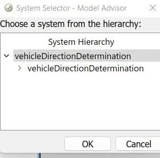
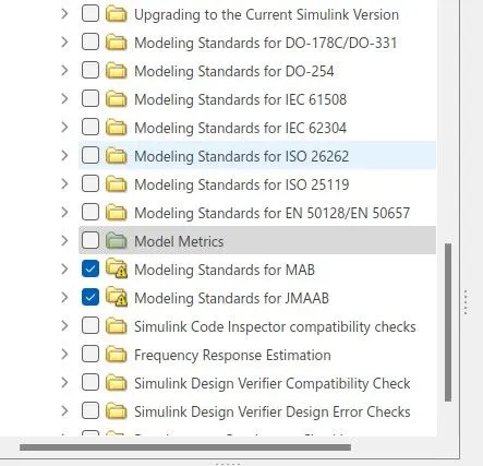
- the report is attached.
RESULTS
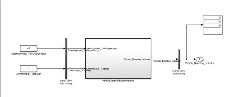
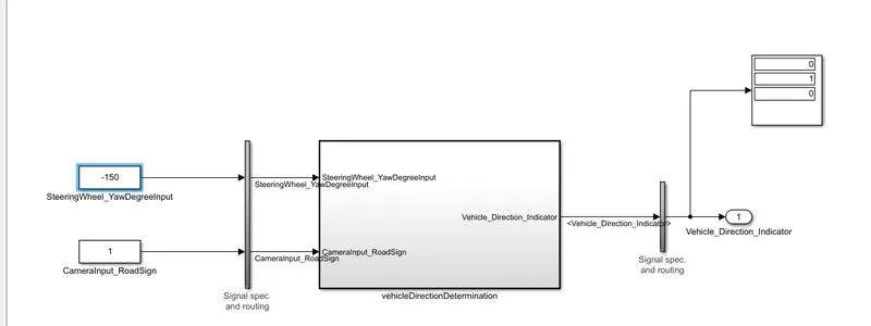
- when my input >=30 my 1st display output is 1 which indicates right turn.
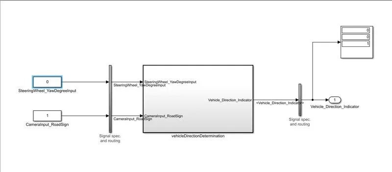
- when my input =0 my 3rd display output is 1 which indicates straight drive.
- when my input<=-120 my 2nd display output is 1 which indicates left turn.