Week-6 Challenge: EV Drivetrain
1.Types of Power converter circuits employed in Electric vehicles:
In electrical systems there are two types of sources are available,namely
- Direct Current(DC)
- Alternating Current(AC)
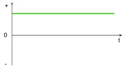
Direct Current:
DC stands for Direct Current, although it is often referred to as “DC Current”. DC current is defined as a unidirectional flow of electric charge. In DC current, the electrons move from an area of negative charge to an area of positive charge without changing direction.
Alternating Current:
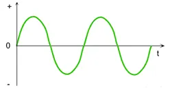
Alternating Current (AC) is a type of electrical current, in which the direction of the flow of electrons switches back and forth at regular intervals or cycles.
Power converter circuits are the circuits which convert from one form of source to another and also between one source like stepup or step down.
TYPES OF POWER CONVERTER CIRCUITS:
- Rectifier(AC to DC)
- Inverter(DC to AC)
- Choppers(fixed DC to variable DC)
- cyclo converters (one frequency AC to different frequency AC)
Rectifier(AC to DC):
- The circuit which converts AC to DC those circuits ate called rectifier.
- These circuits are mostly used in case of battery charging externally from our household services or in comercial charging stations.
- In regenerative braking these rectifiers are necessary if the traction motor / alternator incase of hybrid /internal combustion engine has Alternating type.
Inverter(DC to AC):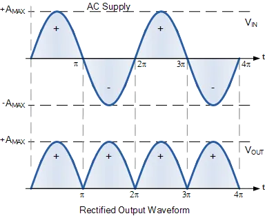
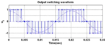
- These circuit which convert DC to AC source.
- These circuits are used for powering the motor if we use AC motors from battery source.
Choppers:
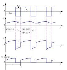
- This circuit which will step up/step down the DC source from one level to another level.
- These circuits are mostly use for auxillary systems like infotainment,lights,powering sensor,etc...
- Mostly battery voltages are in a range of 100 to 200 volts but these auxillary systems requires only 12v or max of 24v(rarly).For this Step down choppers are used.
Cycloconverters:
- This circuit convert from one frequency source to variablie frequency sources.
- This is used for speed control for induction motor.Mostly these circuits are not used in automobiles because the input to these circuits is AC type but in automobile we will have only DC source.
-------------------------------------------------------------------------------------------------------------------------------------------
2.An Electric Vehicle's powertrain with 72V battery pack in shown in the diagram below. The duty ratio for acceleration operation is 'd1' and for the braking operation the duty ratio is 'd2'.
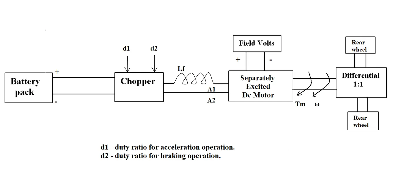
The other parameters of the electric vehicle is given below,
Motor and Controller Parameters:
Rated Armature voltage= 72 V
Rated armature current= 400 A
Ra= 0.5Ω, KΦ= 0.7 Volt second
Chopper Switching frequency= 400 Hz
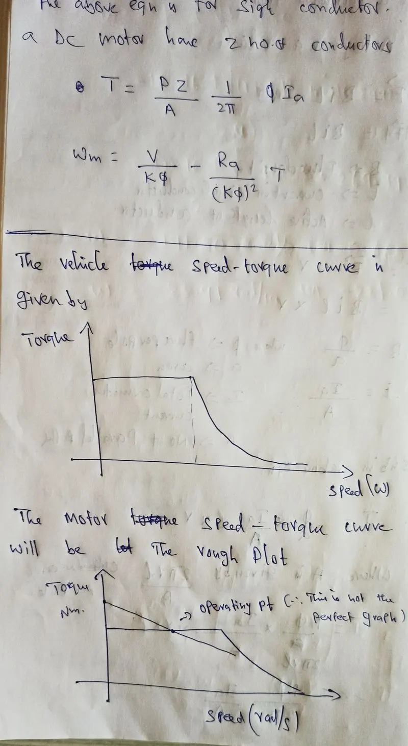
The vehicle speed-torque characteristics are given by the below equation

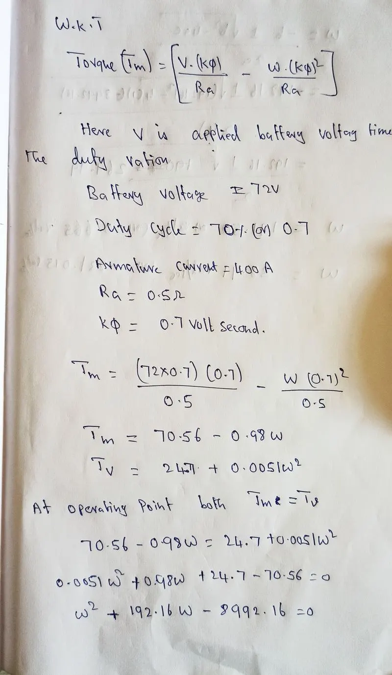
What is EV steady state speed if duty cycle is 70%?
Soln:
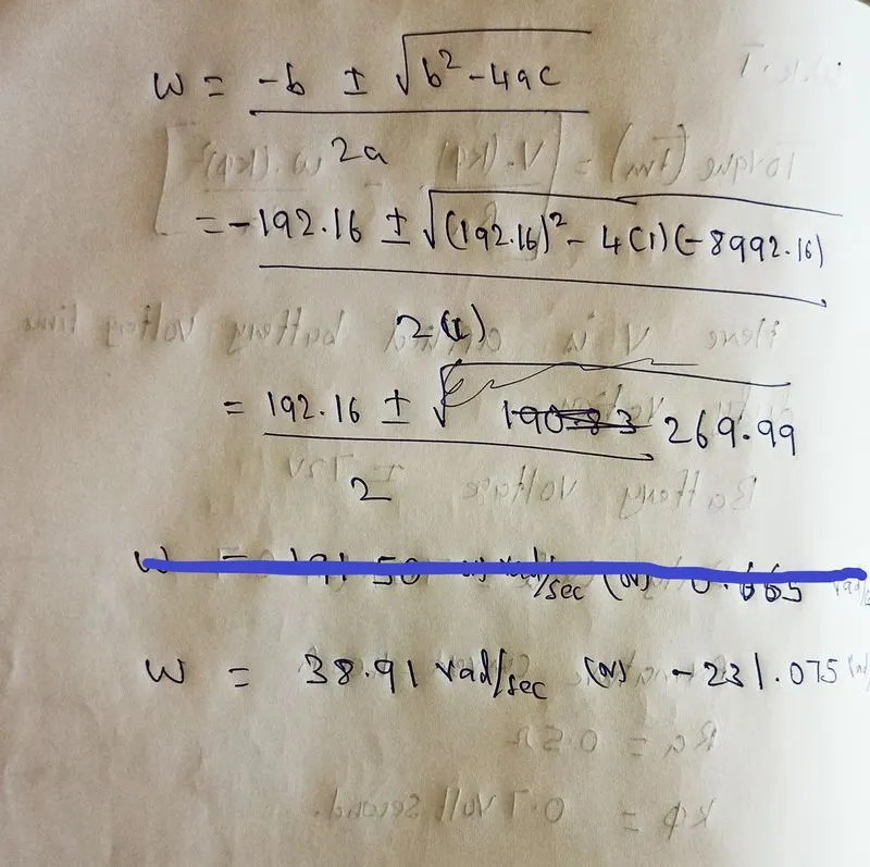
Result:
- The speed of motor with 70% duty cycle is 38.91 rad/sec 372 rpm sey if we have 16 inch tyre then speed willbe around 30kmph.
-------------------------------------------------------------------------------------------------------------------------------------------
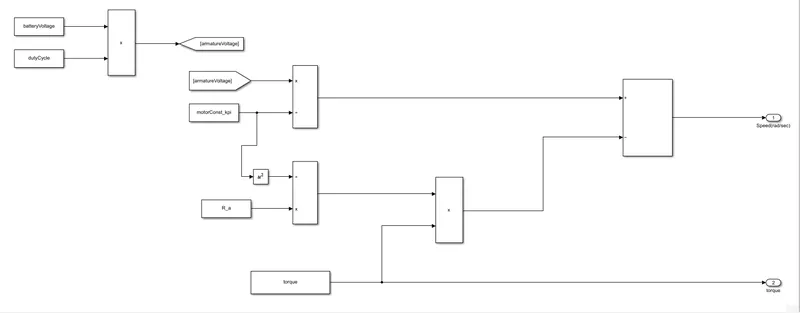
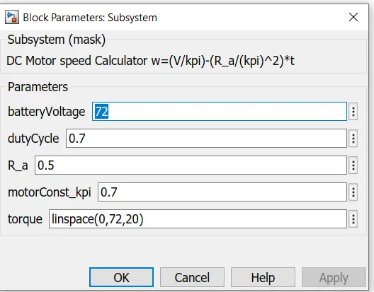
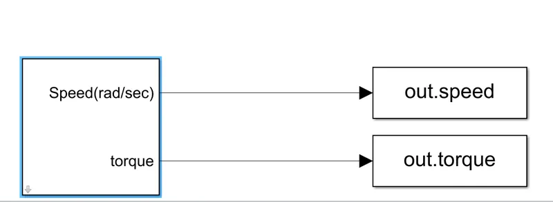
3.Develop a mathematical model of a DC Motor for the below equation using Simulink.
ωω= V/Kϕϕ -Ra/Kϕϕ^2 .T
-------------------------------------------------------------------------------------------------------------------------------------------
4.The authour is talking about the two motors which are used for the propulsion for Electric Vehicle and Hybrid Electric vehicles.The two motors are
- Induction motor
- Brushless DC motor
Induction motor working:
The induction rotor has no magnets – just stacked steel laminations with buried peripheral conductors that form a “shorted structure.” Currents flowing in the stator windings produce a rotating magnetic field that enters the rotor. In turn, the frequency of this magnetic field as “seen” by the rotor is equal to the difference between the applied electrical frequency and the rotational “frequency” of the rotor itself. Accordingly, an induced voltage exists across the shorted structure that is proportionate to this speed difference between the rotor and electrical frequency. In response to this voltage, currents are produced within the rotor conductors that are approximately proportionate to the voltage, hence the speed difference. Finally, these currents interact with the original magnetic field to produce forces – a component of which is the desired rotor torque.
Brushless DC motor working:
The brushless machines, the rotor includes two or more permanent magnets that generate a DC magnetic field (as seen from the vantage point of the rotor). In turn, this magnetic field enters the stator core (a core made up of thin, stacked laminations) and interacts with currents flowing within the windings to produce a torque interaction between the rotor and stator. As the rotor rotates, it is necessary that the magnitude and polarity of the stator currents be continuously varied – and in just the right way - such that the torque remains constant and the conversion of electrical to mechanical energy is optimally efficient. The device that provides this current control is called an inverter. Without it, brushless motors are useless motors.
|
Induction Motor |
Brushless DC Motor |
|
· The rotor is made of solid conductors which are short circuited. |
· The rotor has permanent magnets. |
|
· It doesn’t require Inverter for starting but it required inverter for speed control. |
· It require inverter for starting and for continuous operations |
|
· The operating powerfactor is less 0.85. |
· The operating power factor will be unity. |
|
· It’s efficiency is less compare to brushless DC |
· It’s efficiency is higher than induction motor. |
|
· It has low starting torque. |
· It has better starting torque. |
Observations:
- The author trying to compare brushless dc and induction motor.
- He saying that inuction will be more advantages but this article was published in 2007,in that time the developement of drive for brushless DC was in begining stages,now we have better drive for brushless DC.
- Now because of development i power electronics we have better drive system and more over Tesla now using IPSynRm motors in model 3 its a combination of induction and synchronous reluctance motorwith rotor have special shaped permanent magnets in rotor of the motors.