Final Project: Design of an Electric Vehicle
Aim
To simulate MATLAB model of electric car with battery and DC motor using suitable blocks from Powertrain blockset.
Description
MATLAB/Simulink software is a tool capable of modeling complete EV powertrains of different levels of fidelity and detail and has become an invaluable modeling platform. In this particular project, equation based modelling approach is followed and the dynamics of vehicle motion represented in drive cycles and the vehicle systems is formulated and then implemented in the form of subsystems, blocks and signals within Simulink.
System level Modelling of EV
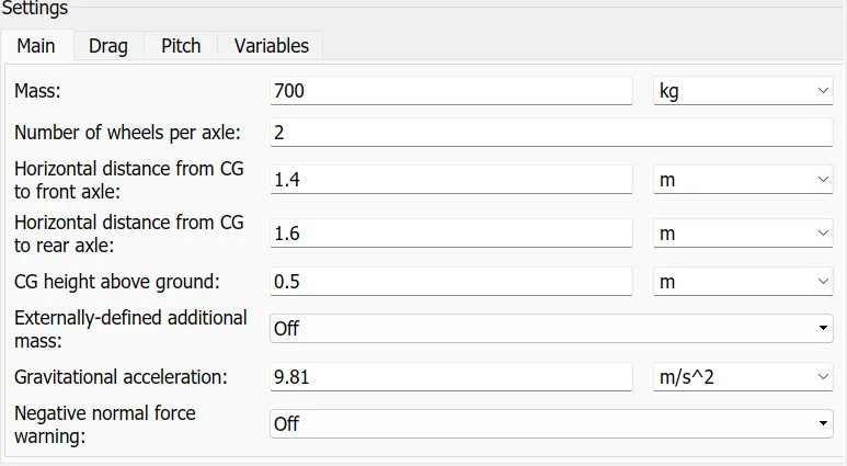
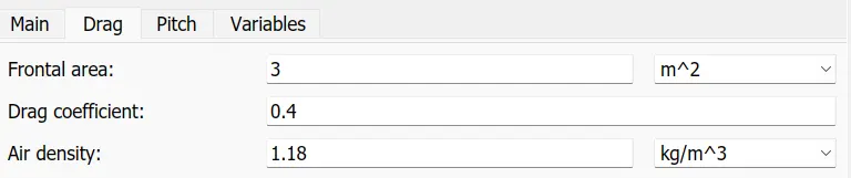
A four-wheel drive model of an electric vehicle is developed . Two wheels place at the front portion and the other two placed at the rear portion. Both real and front wheels are controlled by an DC motor which is controlled by H bridge. The vehicle body placed on the four wheels of the drive with initial parameters of environments like wind, inclined and throttle. For simplicity grade, environmental factors are considered negligible. Before performing the modeling of the four-wheel electric vehicle drive train, we finalize the parameters and behavior of the vehicle body.The vehicle parameters are chosen to be
Dynamics of the vehicle motion
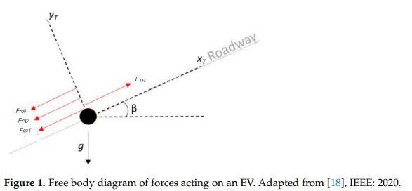
Based on the equations of the vehicle dynamics, the total tractive effort required for the movement of the vehicle is defined as the force required to overcome the rolling resistance, force required for acceleration, force required required to over come the airdrag, force required to climb up a grade.
Drive cycle
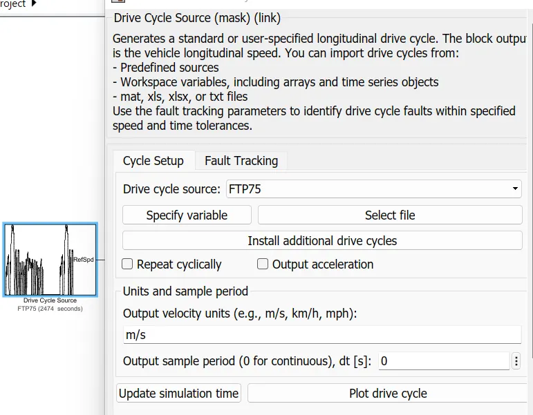
A drive cycle is typically represented by a series of data points which plots vehicle speed against time. Driving cycles are produced to assess the performance of vehicles in various ways, including fuel consumption and pollutant emissions. This is being modelled in MATLAB using drive cycle source.
Longitudinal Driver
Longitudinal driver block is a parametric longitudinal speed tracking controller for generating normalized acceleration and braking commands based on reference and feedback velocities.
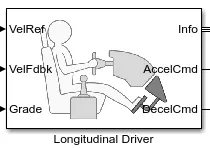
Longitudinal driver block includes a velocity feed back, velocity input, acceleration command and ddeceeleration command.
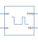
Controlled PWM Voltage
This block creates a Pulse-Width Modulated (PWM) voltage across the PWM and REF ports. The output voltage is zero when the pulse is low, and is equal to the Output voltage amplitude parameter when high. Duty cycle is set by the input value.
The Simulation mode can be set to PWM or Averaged. In PWM mode, the output is a PWM signal. In Averaged mode, the output is constant with value equal to the averaged PWM signal.
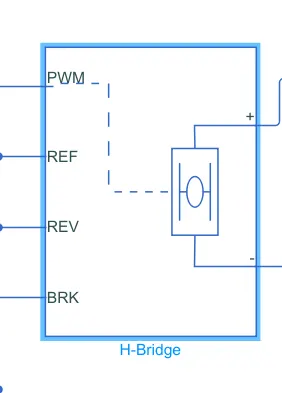
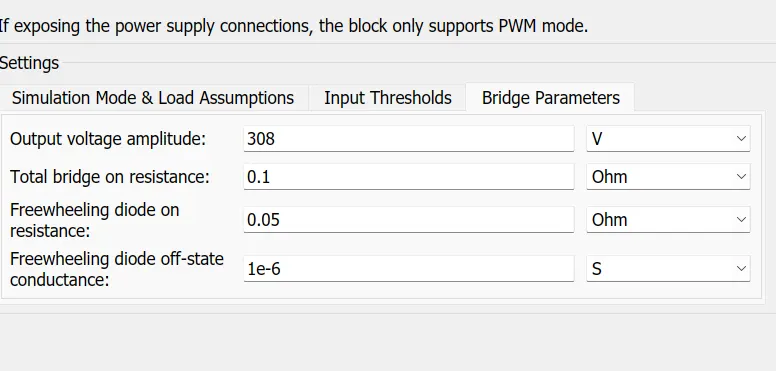
H bridge circuit
This block represents an H-bridge motor drive. The block can be driven by the Controlled PWM Voltage block in PWM or Averaged mode. In PWM mode, the motor is powered if the PWM port voltage is above the Enable threshold voltage. In Averaged mode, the PWM port voltage divided by the PWM signal amplitude parameter defines the ratio of the on-time to the PWM period. Using this ratio and assumptions about the load, the block applies an average voltage to the load that achieves the correct average load current. The Simulation mode parameter value must be the same for the Controlled PWM Voltage and H-Bridge blocks.
If the REV port voltage is greater than the Reverse threshold voltage, then the output voltage polarity is reversed. If the BRK port voltage is greater than the Braking threshold voltage, then the output terminals are short circuited via one bridge arm in series with the parallel combination of a second bridge arm and a freewheeling diode. Voltages at ports PWM, REV and BRK are defined relative to the REF port.
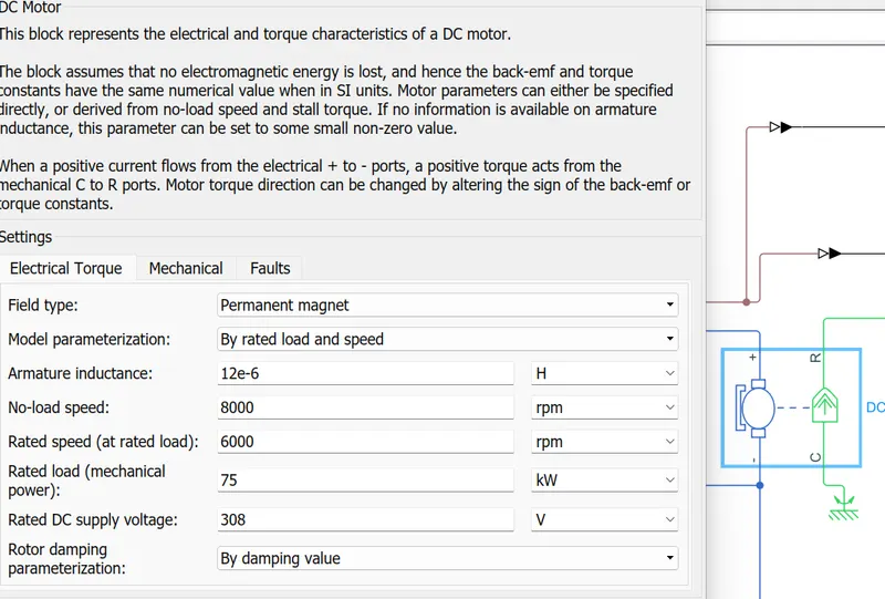
DC Motor
The dc motor block is used to represent the electrical and torque characteristics of the motor. Motor paraameters are specifiied directly or derived from rated load and stall torque.
Vehicle Subsystem
The vehicle subsystem is modlled by vehicle body and two fron wheel tyres and two rear tyres. Gradient and wind constant are assumed to be zero.
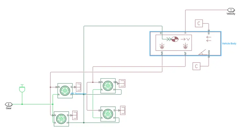
Tires represents the longitudinal behaviour of a highway tire characterized by tire Magic Formula. It is built from tire road interaction formula . Four wheels are connected to the vehicle body.
Battery Model
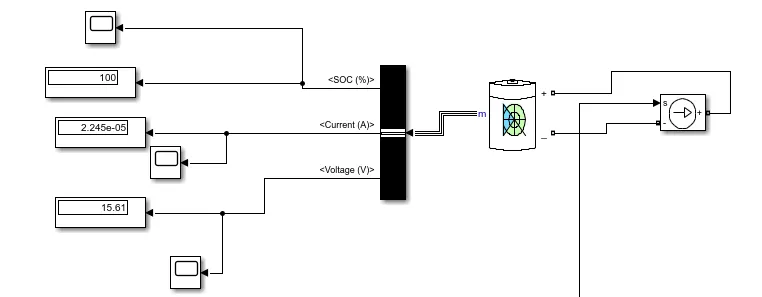
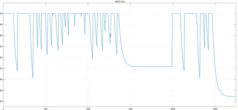
Battery model is selected from Simscape library and current of the motor connected to the controlled current source of battery. The outputs of battery model provides information about voltage, current and SOC.
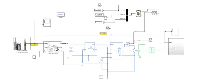
THe complete model of EV is shown below.
Working
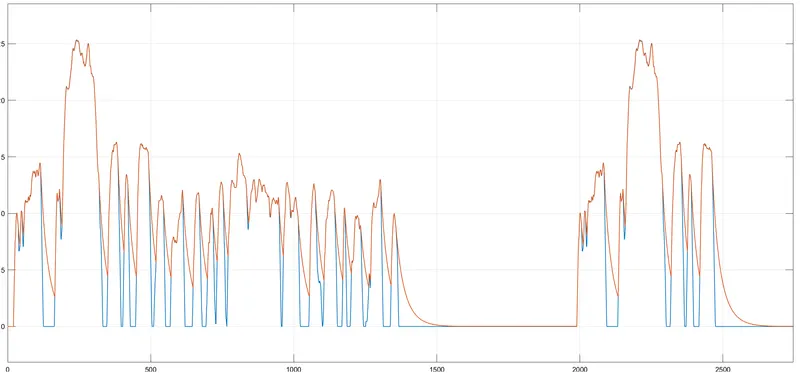
In this model input signal or drive cycle data is given to longitudinal driver block. The controlled PWM signals generate PWM signals for turning ON and turning oFF the switches in H bridge rectifier which controls the motor circuit. Th motor gives the required torque output and velocity output can be fed back to the longitudinal driver. The speed of vehicle and output velocity of the vehicle can be compared in the scope.
The SOC of the battery is shown below.
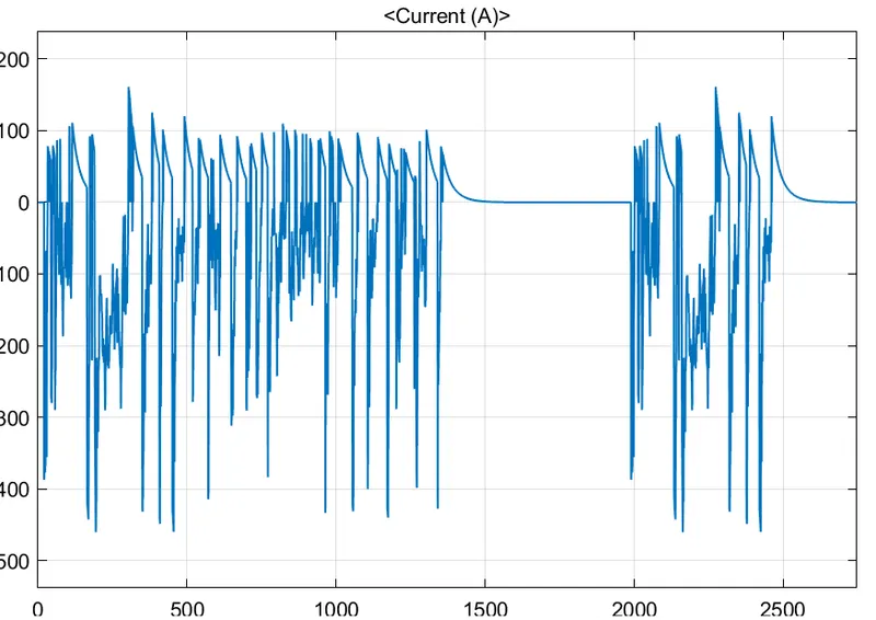
The current drawn from the battery is shown below.