Final Project: Design of an Electric Vehicle
# Electric vehicle design:
- Electric vehicle:
- The electric vehicle uses battery source and electric motor for its propulsion.
- Electric vehicles have high efficiency compared to ICE. Losses in EV are also less.
- The motors used for propulsion of EV can be any of the below: 1.Permanent magnet synchronous motor 2. Three phase induction motor 3. BLDC motor 4. Switched reluctance motor
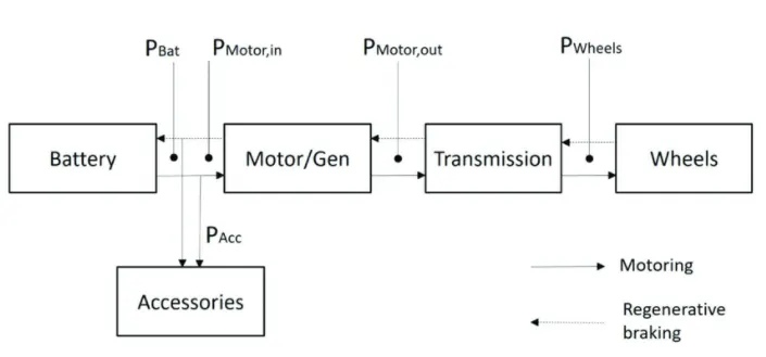
# Block Diagram of EV:
- Simulink Model:
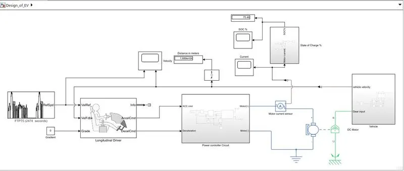
- Blocks used:
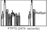
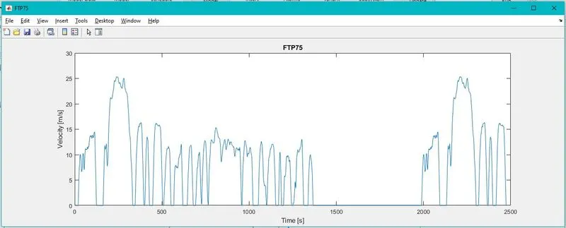
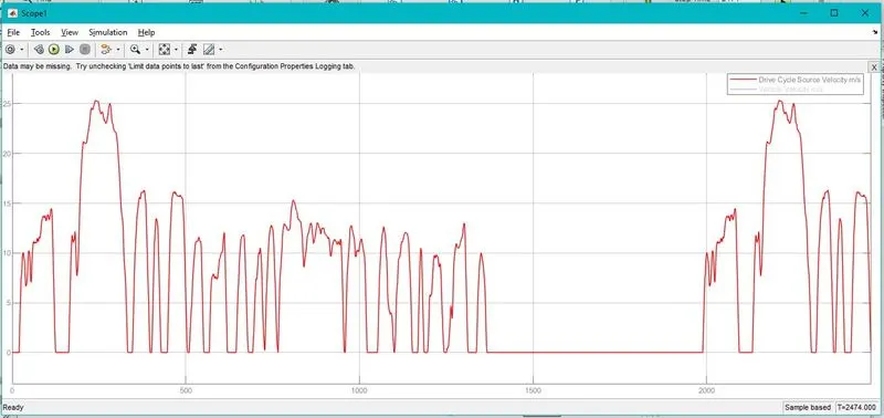
1. Drive cycle: For the simulation FTP75 Drive cycle is used.
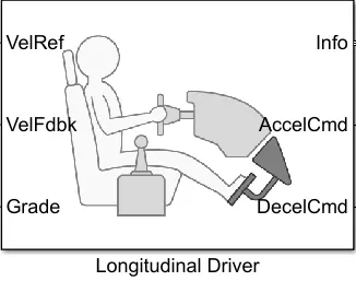
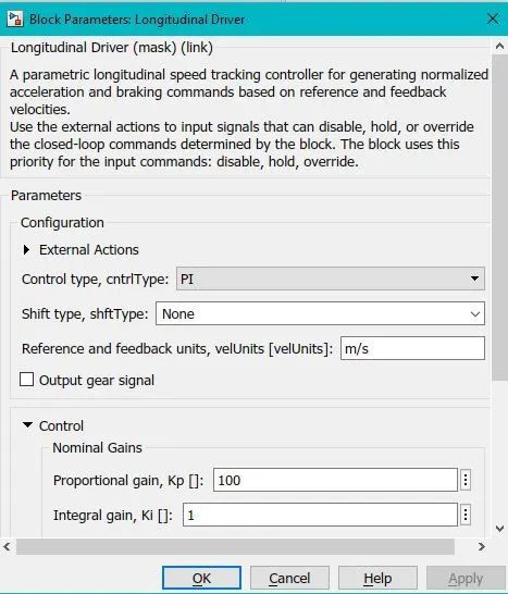
2. Longitudinal Driver: It is used to create longitudinal speed tracking controller and it is based o reference and feedback velocities.
3. Power controller block:
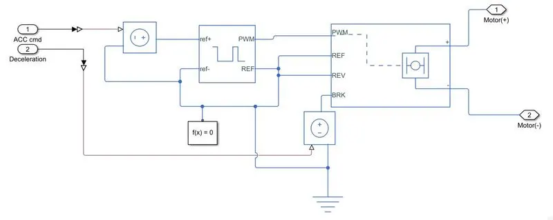
4.Controlled voltage source block: This block is used to maintain the specified voltage at its output regardless of the current flowinng through source.
5. Controlled PWM voltage: Used to create pulse width modulated voltage.
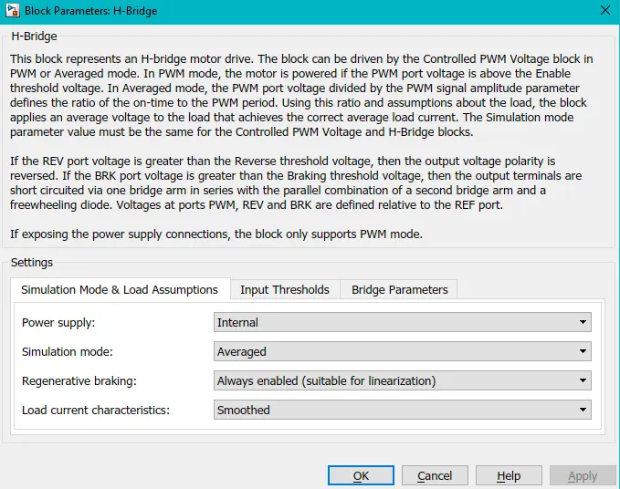
6. H- bridge: Used to change the polarity of voltage applied across DC motor so as to run the motor in forward and reverse direction as per input command.
7. Current sensor block: Used to measure current flowing through H- bridge.
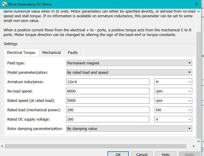
8. DC motor: To convert electrical energy to mechanical energy. In regenrative braking motor the mechanical energy gets converted into electrical energy.
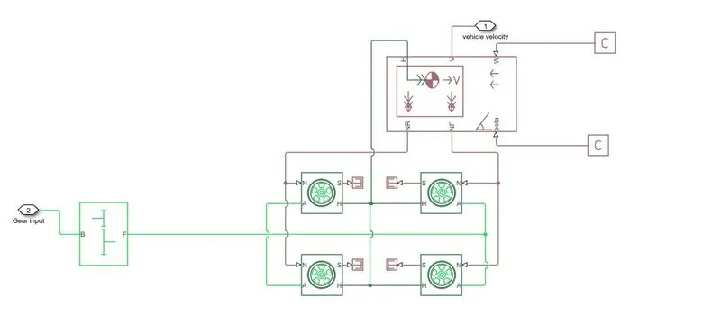
8. Vehicle body: The block represents a two axel vehicle body in longitudinal motion. The block accounts for body mass, aerodynamic drag, road incline weight distribution between axel due to acceleration, road profile.
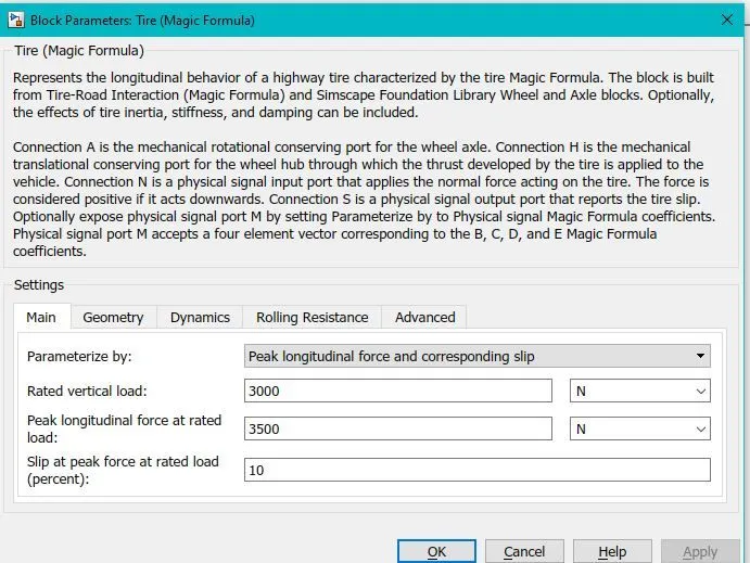
9. Tire:

10. Simple Gear:

Calculations: Linear peak velocity of vehicle as per drive cycle(v)
v= 26m/s
Rolling radius of wheel(r)= 0.3m
v= r*ω
ω = v/r = 26/0.3 = 86.67 rad/sec
Rotational speed of wheel in rpm (Nw)=60*ω/2π = 60*86.67/2π = 827.63 rpm
Rated speed of motor at rated load(Nm)= 5000rpm
Gear ratio= Nm/Nw= 5000/827.63= 6
- Output:
1.Drive Cycle:
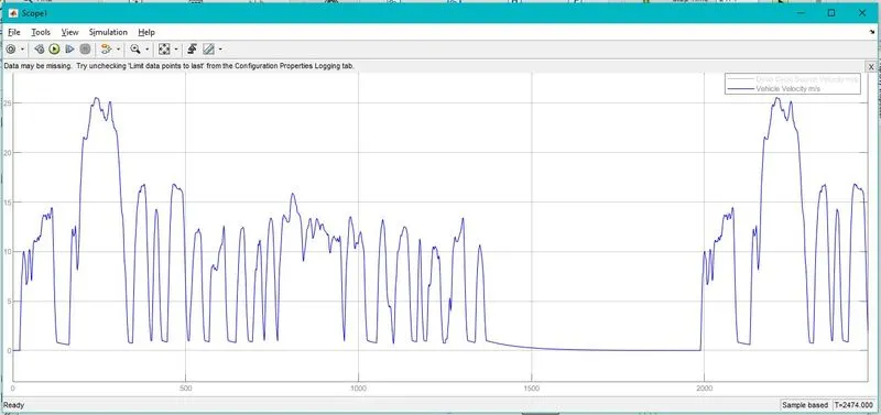
2. Vehicle Velocity:
3. Drive cycle and vehicle velocity:
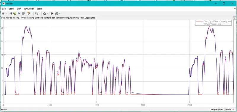
- The vehicle velocity plot is following the drive cycle velocity curve, it means the controller trying to minimize the error in between them.
- There is some difference in drive cycle and vehicle velocity, this is beacause of inertia of vehicle mass.
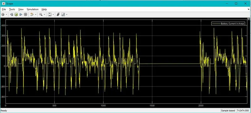
4. Battery current:
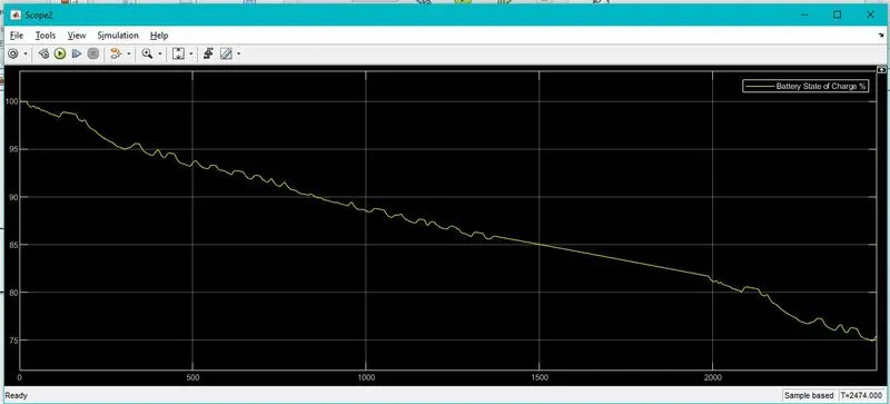
5. Battery SOC%:
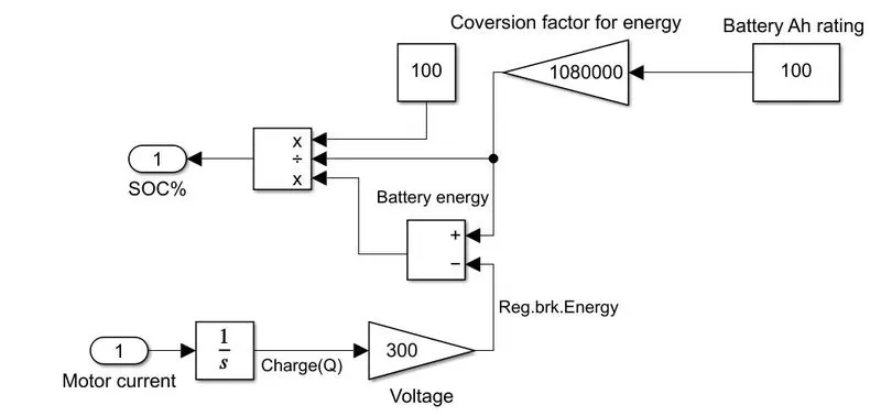
- The motor current is integrated to get value of charge, which is then multiplied with battery voltage to get energy being consumed by motor and also energy being generated during regenerative braking.
- This energy is then subtracted or added from the intial battery energy to get the current energy state of the battery.
- Initial battery energy is calculated at 100% charged condition, from the Ah rating of the battery.
- The current energy state of the battery is compared with initial energy state to obtain the state of charge of the battery in percentage.
- Calculations:
Assuming: Ah rating of battery=100Ah at rated voltage 300V
Initial enegy state of battery(Eb)= Rated voltage*Ah rating*3600
Eb= 300*100*3600
Eb=108000000 J
Motor current I=dQ/dt
Q= ∫I.dt
now, P= V.I = V.Q/t
Energy(Et)= P.t= V.Q
Et= Q*300 J
SOC% = [(Eb± Et)/Eb]*100