Week - 4
#Part 1:
- Simulink Model:
- Chart:
- Symbols Pane:
- Description:
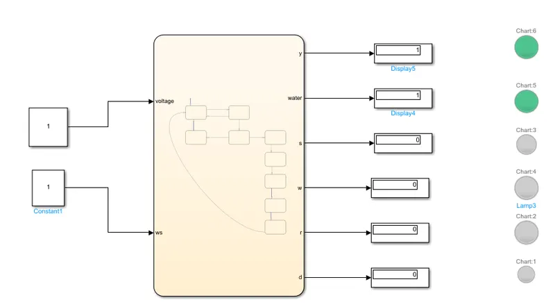
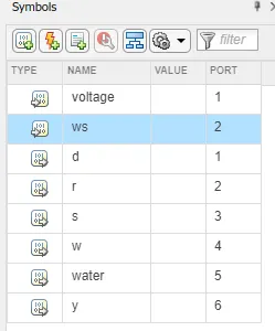
- In the model constant blocks are used to give input to chart. Inputs are Voltage and Water Supply.
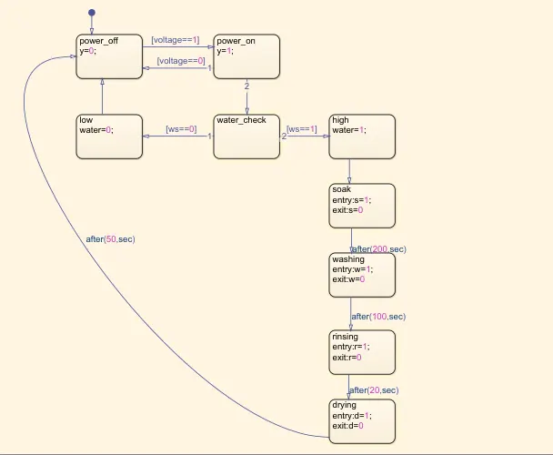
- In the chart when voltage is available i.e. voltage ==1 then washing machine starts. And go for water check. If water is low then machine turns off.
- If water level is high then starts the process of soaking. Soaking time given is 200 sec. After 200 sec soaking stops and washing starts for next 100 sec.
- Rinsing period is 20 sec and drying is done for 50 sec.
- After completion of all process machine turns off.
- Lamps are used to show the ongoing process of machine.
- Conclusion:
Thus the stateflow logic for washing machine machine is executed.
# Part 2:
- Simulink Model:
- Chart:
- Symbols Pane:
- Description:
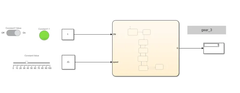
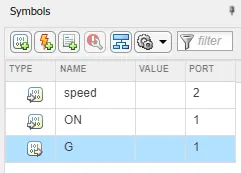
- Switch is used to turn on and off the vehicle. When on then lamp glows green.
- Slider block is used to vary speed of vehicle.
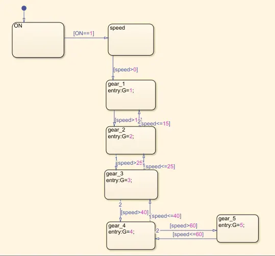
- When switch is on, 'ON' block activates and go for checking speed of vehicle. If speed is greater than 0 and less than equal to 15 then vehicle operate at gear_1.
- If speed is between 16 to 25 then vehicle run at gear_2 and so on as per condition given.
- The output indicates the gear number on which vehicle is running.
- Conclusion:
- Thus stateflow logic chart can be utilized to indicate the gear number based on speed of the vehicle.