Final Project: Design of an Electric Vehicle
Project:- Design of an Electric Vehicle
Aim:-
To create a MATLAB model of an electric car which uses a battery and a DC Motor by chossing suitable blockset from powertrain block set and to prepare report on the created model.
Objective:-
Report on developed model on the following
1) System Level Configuration
2) Model Parameters
3) Result
4) Conclusion
Description:
Electric Vehicle:-
Electric Vehicle uses one or more electric motor for propulsion. It can use collector system from extravehicular source to power the vehicle or it can be powered by using stored energy from battery. EVs are not limited to surface vehicle which are also used in spacecrafts, Aircrafts and even in underwater vessels.
Examples:- Electric powered Submarines which uses batteries which are charged on the surface by using Gasoline or diesel engine, Mars helicopter Ingenuity, Electrical powered spacecraft propulsion.
Here we are going to design an Electric Car by using MATLAB and Simulink.
Components:-
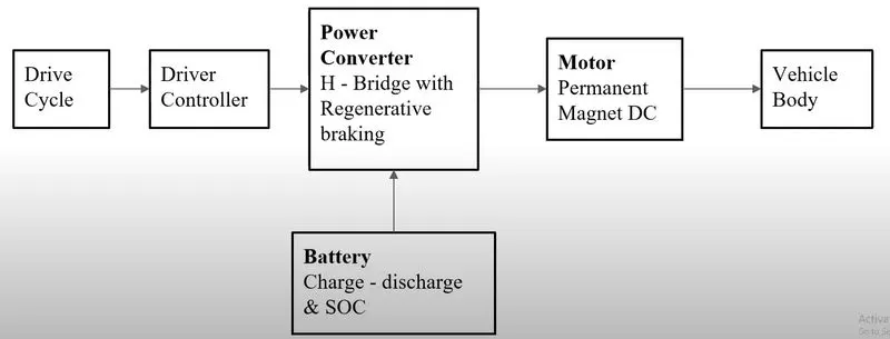
The Main components of an EV are Battery, Motor Controller(Power converter), Motor/Generator and Vehicle body
The Drive Cycle which is used in determaining the vehicle movement with respect to time.
The block diagram is as seen below
Block Diagram:-
Model:-
Vehicle body Subsystem:-
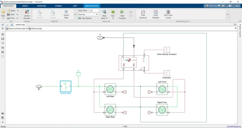
The vehicle body subsystem contains vehicle body block, Tire block since we are designing a four wheel vehicle four tyre block sets are used, Gear block.
The Velocity taken as output from the block and the input is the motor output which is provided to the simple gear block.
- Vehicle Body:-
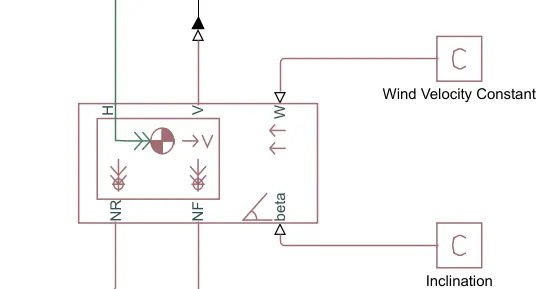
Vehicle body block contains the parameters such as body mass, aerodynamic drag, grade, Center of gravity of vehicle body, externally defined mass, Pitch dynamics.
The Input ports are W which represents the wind velocity and beta which represents Grade angle, which are considered constant.
The output ports of the block are V, NR, and NF which represents Velocity in m/s, Normal force on Rear Wheel in N, and Normal force on Front Wheel in N respectively.
Vehicle Body Parameter:-
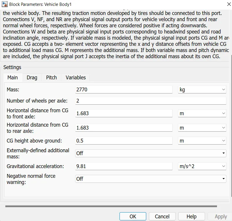
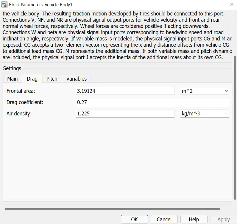
In Vehicle body parameters the Mass, Horizontal distance from CG to Front axle and rear axle and CG height from ground are modified and drag coefficient, frontal area, Air density are modified and Pitch parameters are turned on and kept constant
Vehicle body Main Parameter:-
Vehicle Body Drag Parameter:-
- Tire Block:-
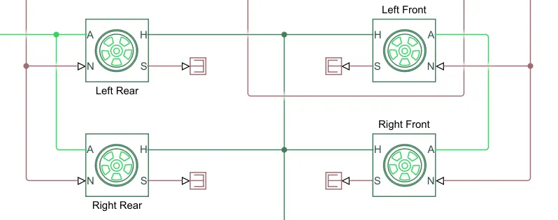
Tire block:-
All four Tire block which is connected through hub from vehicle body block hub and the front and rear wheels are connected by using the Axle port separately and the front wheels are connected to NF trough N port in tire block wheres as normal force signal is provided to the tire and NR port from vehicle body delivers normal port signal to rear wheels through N port.
The S port Slip of tire is considered nil in the simulation.
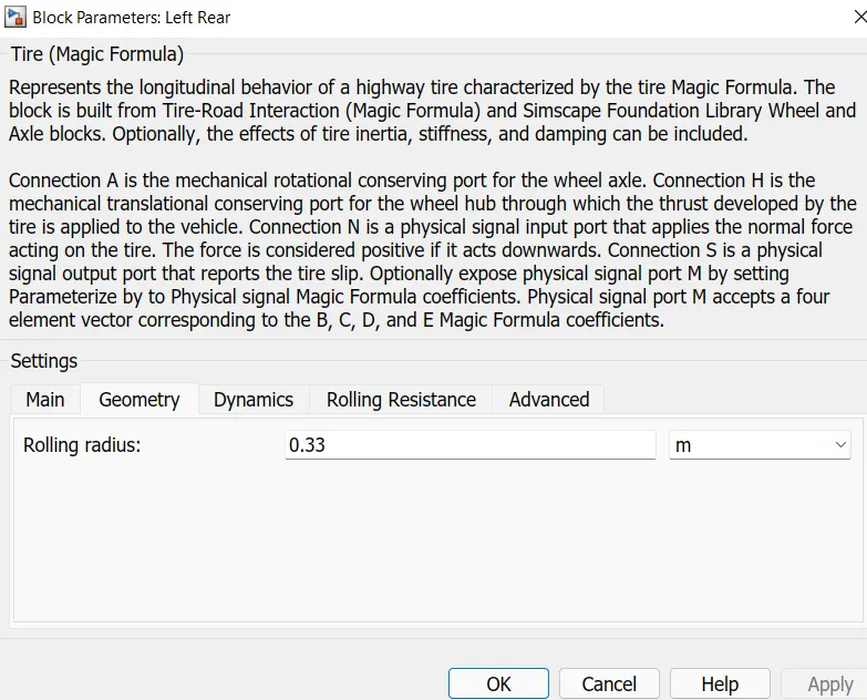
Tire Parameters:-
Tire parameter of rolling radius is modified and other are kept constant.In parametres the rolling raesistance can be changed based on the tire pressure and effect of inertia can also be used but in our simulation we use the constant value.
- Gear Block:-
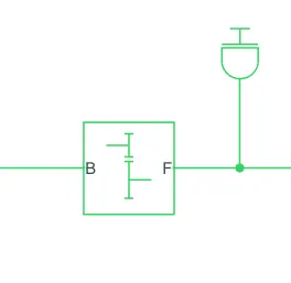
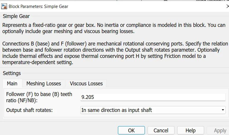
The Gear block is provided with input from the DC Motor and an intertial constant is provided to its output and the gear ratio is set to 9.205 and other parameters are kept constant. The gear output is provided to the rear axle as input.
Gear Parameters:-
Motors and Control Subsytem:-
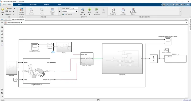
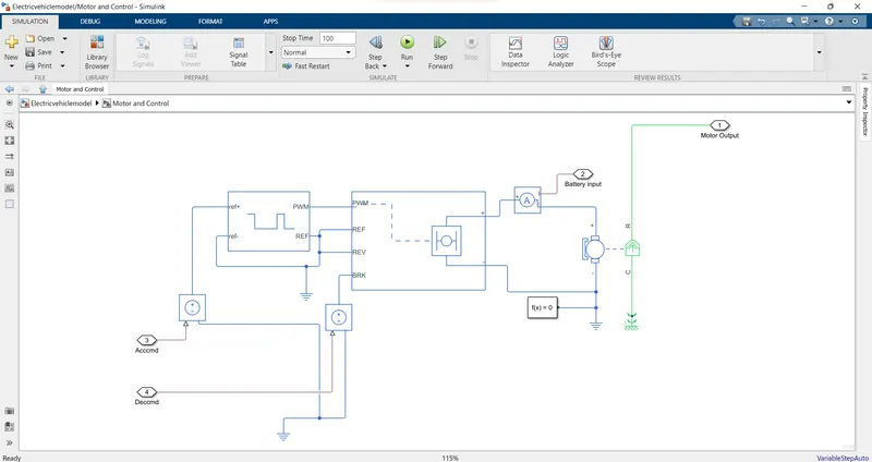
This Subsystem contains DC Motor, H-Bridge and Controlled PWM Voltage blocks and the inputs for this blocks are from Longitudinal driver block which provides Accelaration Command and Decelaration command as input signal and output signals are from Battery sensor which is provided to the battery Block and the DC Motor output which is provided to vehichle body subsystem.
- DC Motor:-
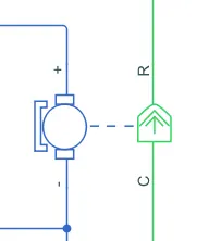
We have considered DC Motor to power the vehicle, as motor is considered as the power source of the vehicle inorder to accelarate the vehicle
Here in DC Motor the + and - is the input which is provided through a H-Bridge converter and the output of motor terminal R is provided as input to the gear block and the C port is connected to mechanical rotational reference.
DC Motor Parameters:-
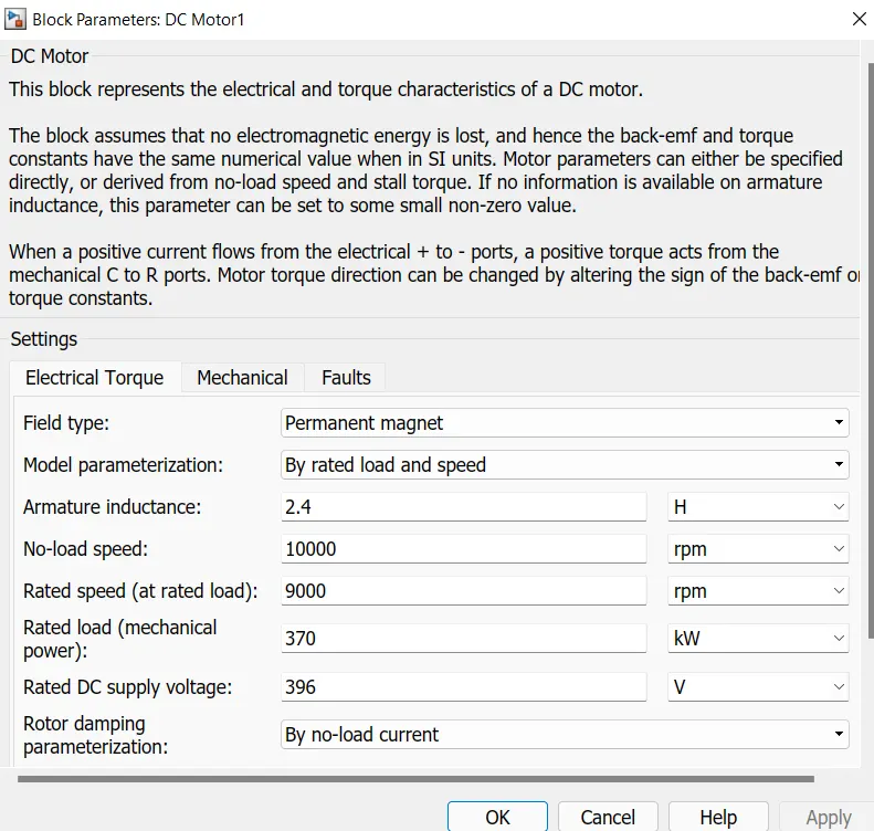
Here the motor power of 370 KW permanent magnet DC Motor is chossen and the parameters are modeled by rated load and speed and no load speed and rated speed, rated load power and DC supply voltage parameters are modified and others are kept constant.
- H-Bridge Block:-
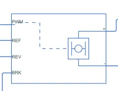
The H-Bridge block contains PWM, Ref, Rev, Brk as input ports and +, - as output ports. The output port as connected to the DC motor and input signals are recieved through a PWM convertor block and from controlled voltage source for Brk port.
The + terminal is connected to DC motor through the current sensor and the - terminal is coneected to the electrical reference and solver configuration along with the DC Motor - terminal.
H-Bridge Parameters:
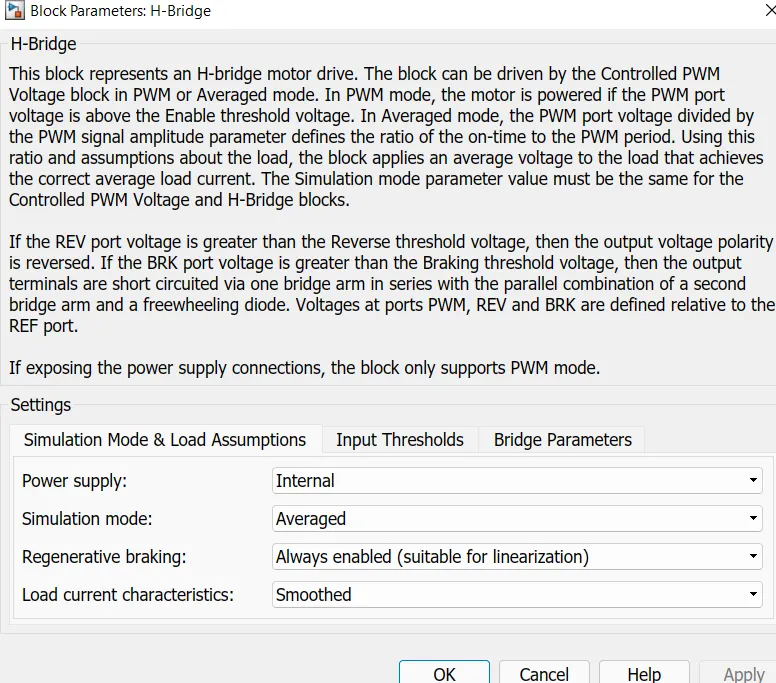
In order to reduce the simulation time, Simulation mode is averaged and regenerative braking is kept active through out the simulation and the load current is smoothed.
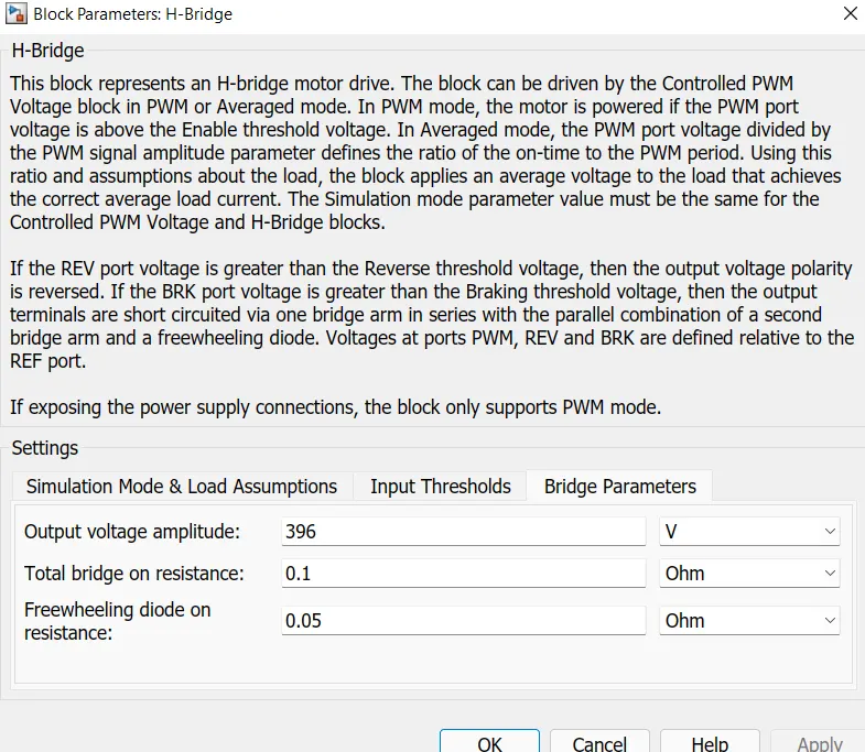
The output voltage amplitude is modified inorder to meet the DC Motor rating and other parameters are kept constant.
H-Bridge Simulation Mode and Load Assumption Parameter:-
H-Bridge - Bridge Parameter:-
- Controlled PWM Voltage Block:-
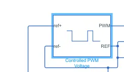
Controlled PWM Voltage block has ref+ and ref- as input port in which ref+ is connected to the controlled voltage source. The output port are PWM port which is connected to H-bridge PWM port and ref is connected with ref and rev of h-bridge.
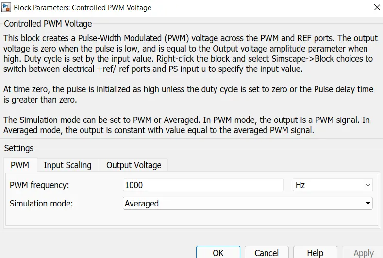
Controlled PWM Voltage Parameters:
In this block the simulation mode is averaged inorder to reduce the simulation time and all other parameters are kept constant
Battery Subsystem:-
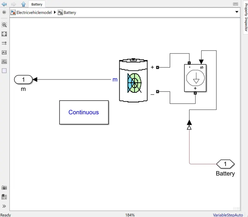
This subsystem contains a Battery block, Controllered Current source.
Here the current sensor provides input to the Controlled current system block which in turn provided to battery block and the battery voltage and current and SOC are monitered analysed by using the model
- Battery Block:-
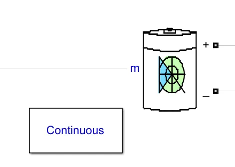
The battery block requires powergui to run hence a power gui block is taken and has simulation type is set to continuous. The battery block has two input terminals + and - which are powered by using the controlled current source
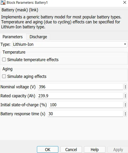
Battery Parameters:-
Lithium Ion battery is choosen and nominal voltage is set to 396 V as it can supply the DC Motor and rated capacity is modified to 239.9 Ah and other parameters are kept as default value.
Longitudinal Driver Block:
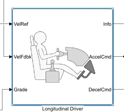
Longitudinal Driver block contains Velref, VelFdbk, grade as input and Info, AccelCmd, DecelCmd as output port.
VelRef port has the input from the drive cycle data and VelFdbk is velocity feedback whick is taken from the velocity output from vehicle body subsystem and grade is consided zero in our simulation and info values are provided to end terminal since we are not using the port.
AccelCmd and DecelCmd are output from the block and which are provided as input to the Motor and control subsystem and parameters are kept as default for this block.
Drive Cycle Subsystem:-
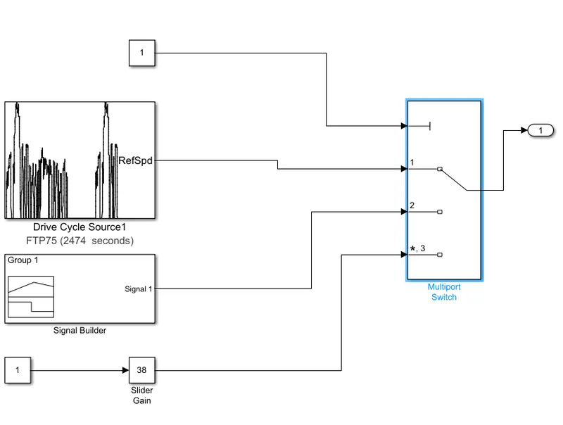
Drive Cycle Subsystem consist of Multiport Switch which is used in chossing the drive cycle we prefer
In the above model we use Drive cycle source block which is having a FTP75 drive cycle data and signal builder block used to generate our own drive cycle and a slider gain is used to change the value during simulation time.
While using slider gain we need to make sure that the Controlled PWM Voltage parameter is set to PWM simulation Mode hence we can change the value in real time.
Output:-
The drive Cycle FTP75 is chosen and the output is observed.
Battery Output:-
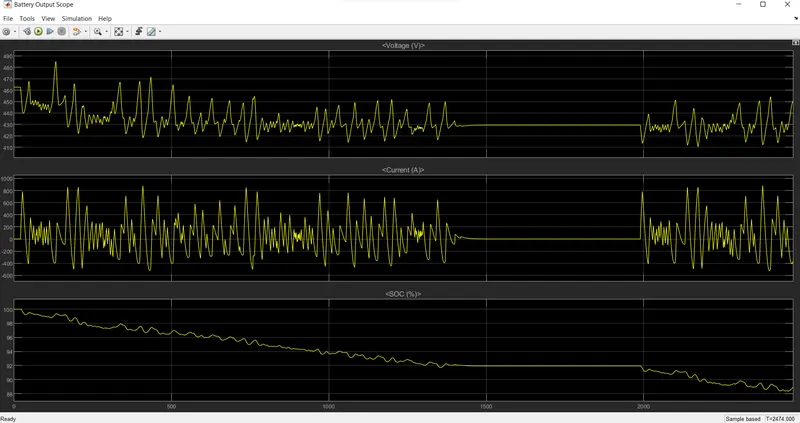
The Battery Output contains Voltage, Current and SOC % for the given drive cycle we can see the current value which tends towards negative which represents the active regenerative braking which functions during the decelaration of vehicle and State of charge for the given drive cycle is from 100% to 88.7% for distance of for 21003 meters i.e., 21 km
Driver Cycle Vs Output Velocity:-
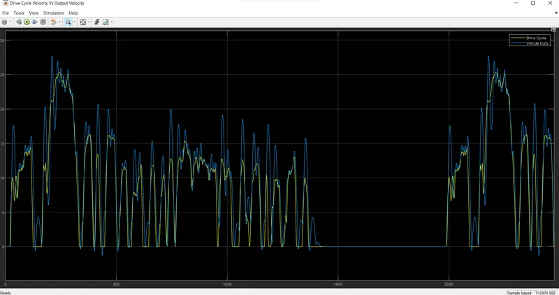
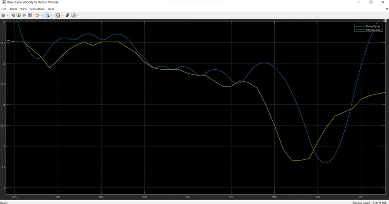
By observing the data between the drive cycle and output velocity the is seem to be a small delay which is due to the inertia of the vehicle which can be clearly observed by zomming the graph which is seen as below.
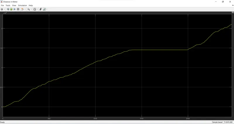
Distance Scope:
Conclusion:-
The FTP75 drive cycle has an average speed of 35 kmph by using the distance scope we measure that it has travelled a distance of 21003 m that is 21 km for a period of 2474 seconds that is 41 Minutes. Thus the vehicle has covered the distance as per the FTP75 cycle data with a discharge rate of 11.3% of battery thus providing an effective performace with a lower discharge rate and more over the response of the vehicle is good which is observed through the drive cycle data vs the vehicle velocity data.
Thus overall the vehicle performance was evaluated by using the model developed using simulink/MATLAB.
Result:
Thus the Modelling of EV Vehicle which uses battery and Dc Motor is done and a detailed report is created based on the objectives provided and conclusions are made based on the output.