Final Project: Design of an Electric Vehicle
FINAL PROJECT
ELECTRIC VEHICLE
AIM:
To create a MATLAB model of electric car which uses a battery and a dc motor. Choose suitable blocks from powertrain block set.
INTRODUCTION OF EV:
All-electric vehicles (EVs), also referred to as battery electric vehicles, have an electric motor instead of an internal combustion engine. The vehicle uses a large traction battery pack to power the electric motor and must be plugged in to a wall outlet or charging equipment, also called electric vehicle supply equipment (EVSE). Because it runs on electricity, the vehicle emits no exhaust from a tailpipe and does not contain the typical liquid fuel components, such as a fuel pump, fuel line, or fuel tank.
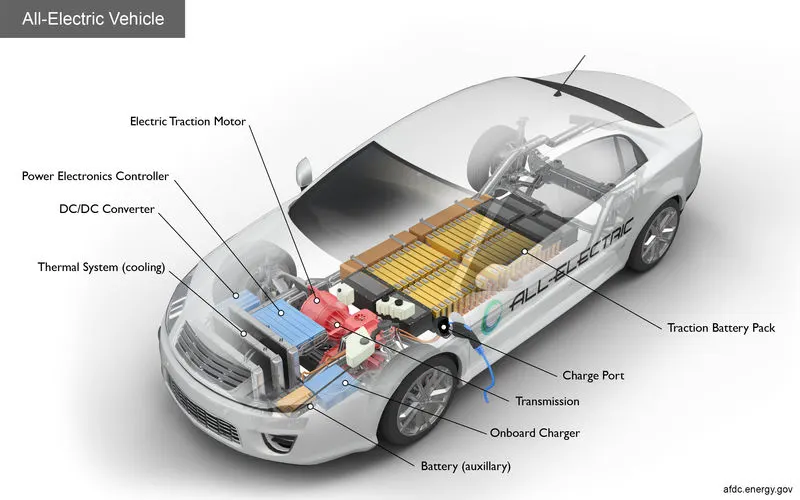
Key Components of an All-Electric Car
Battery (all-electric auxiliary): In an electric drive vehicle, the auxiliary battery provides electricity to power vehicle accessories.
Charge port: The charge port allows the vehicle to connect to an external power supply in order to charge the traction battery pack.
DC/DC converter: This device converts higher-voltage DC power from the traction battery pack to the lower-voltage DC power needed to run vehicle accessories and recharge the auxiliary battery.
Electric traction motor: Using power from the traction battery pack, this motor drives the vehicle's wheels. Some vehicles use motor generators that perform both the drive and regeneration functions.
On-board charger: Takes the incoming AC electricity supplied via the charge port and converts it to DC power for charging the traction battery. It also communicates with the charging equipment and monitors battery characteristics such as voltage, current, temperature, and state of charge while charging the pack.
Power electronics controller: This unit manages the flow of electrical energy delivered by the traction battery, controlling the speed of the electric traction motor and the torque it produces.
Thermal system (cooling): This system maintains a proper operating temperature range of the engine, electric motor, power electronics, and other components.
Traction battery pack: Stores electricity for use by the electric traction motor.
Transmission (electric): The transmission transfers mechanical power from the electric traction motor to drive the wheels.
Now coming in my project,
All values are assumptions,
BLOCK DIAGRAM:
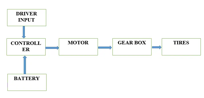
BLOCK EXPLANATIONS:
1. DRIVER INPUT
This is the driving cycle input from the system. also called driving throttle. different driving cycles are used to our project. the drive fed to the multi port switch. in our project different drive input block can be used. in the figure show in beow.
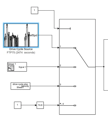
Below the figure showing to the parameterize to drive cycle source.
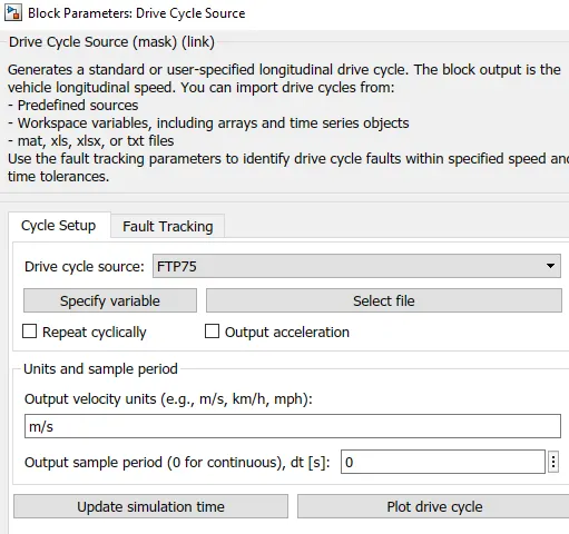
The drive output is fed to the driver. i.e. longitudinal driver.
LONGITUDINAL DRIVER:
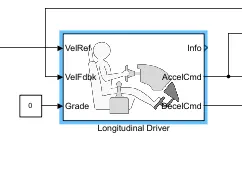
The longitudinal control to the PI controller for default conditions. This also generating for accelration and braking commands. The reference velocity is connected from drive inputs signals. In road way or concrete the vehicle grade can be zero. some vehicle moving to over the hill or down the hill surface, so grade value can be changed.
2. CONTROLLER
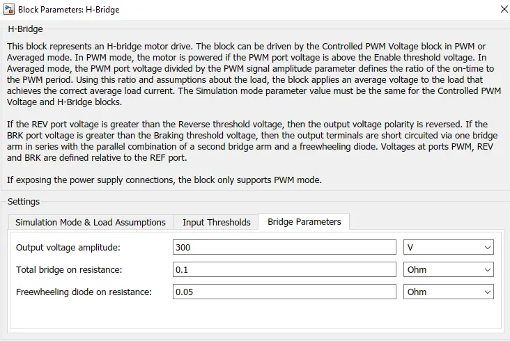
The controller used for in our project H-bridge converter can be used. This part can be mainly used to the motor speed-torque controlling purposes. and also control to battery current. For limiting the SOC.
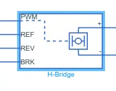
This block achieved by PWM signals. The output 2 ports are connect to the motor. This block achieved reverse and forward braking and moting actions.
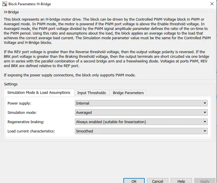
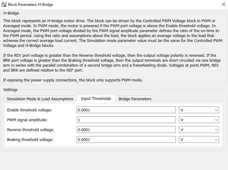
The figure given below by paramerterized the h-bridge block,
3. MOTOR
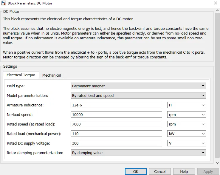
In this type is PM DC motor can be used for in our project. the motor operated to 50kw power supply. the also produce the back emf this controlling for h-bridge circuit. the motor connect with gear shaft.
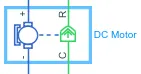
in motor parameterized by given below,
4. GEAR-BOX
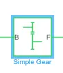
The gear shaft connect to motor. The most important things is the gear ratio. This will generated for the motor speed. In our project the simple gear block can be used for skips the long duration of simulations. the gear also connected to vehicle body with tire.
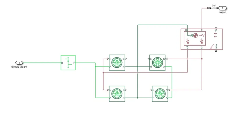
The tires are 2 pairs. one pair is rear and another is front wheel. the gear block connected in rear wheel. the wheel generated for rolling resistance force.The wheel in our project are constant value. The vehicle body is connected for the tires. the block is represents a two-axle vehicle body in longitudinal motion. The block accounts for body mass, aerodynamic drag, road incline, and weight distribution between axles due to acceleration and road profile. The vehicle can have the same or a different number of wheels on each axle. Optionally include pitch and suspension dynamics or additional variable mass and inertia. The vehicle does not move vertically relative to the ground.
Connection H is the mechanical translational conserving port associated with the horizontal motion of the vehicle body. The resulting traction motion developed by tires should be connected to this port. Connections V, NF, and NR are physical signal output ports for vehicle velocity and front and rear normal wheel forces, respectively. Wheel forces are considered positive if acting downwards. Connections W and beta are physical signal input ports corresponding to headwind speed and road inclination angle, respectively. If variable mass is modeled, the physical signal input ports CG and M are exposed. CG accepts a two- element vector representing the x and y distance offsets from vehicle CG to additional load mass CG. M represents the additional mass. If both variable mass and pitch dynamics are included, the physical signal port J accepts the inertia of the additional mass about its own CG.
5. BATTERY
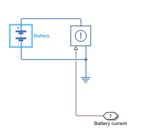
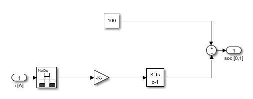
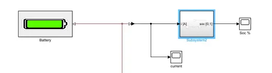
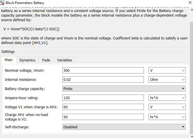
in our project are used at simple battery. this 120aAh rating. and subsystem of the SOC estimation for battery current fed to Soc circuit.
battery parameter,
PROJECT SIMULATION
BATTERY OPERATED TO DC MOTOR MODEL
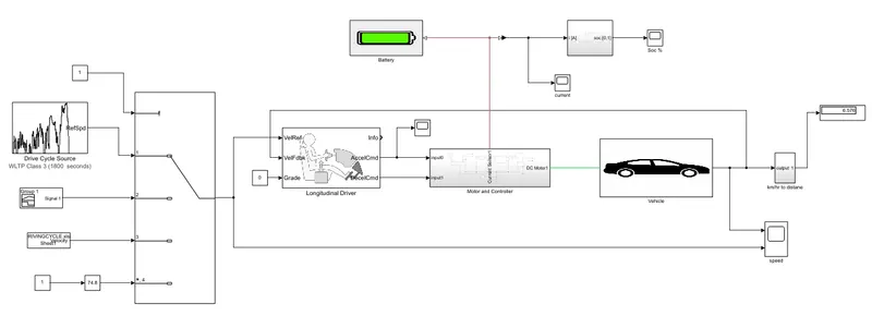
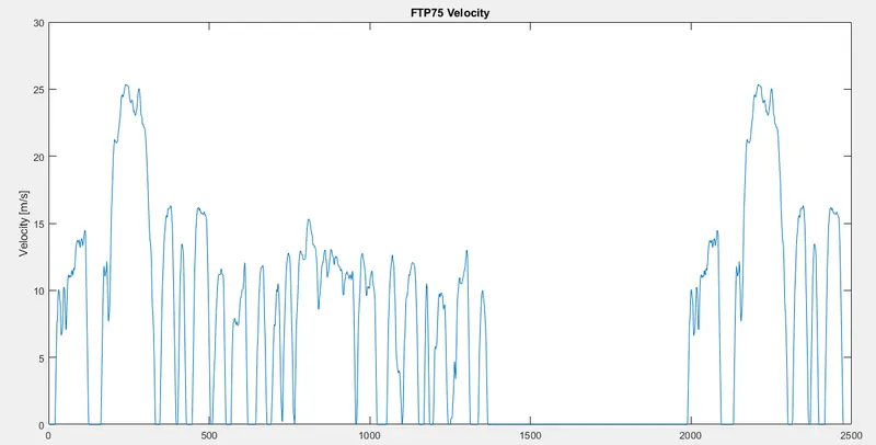
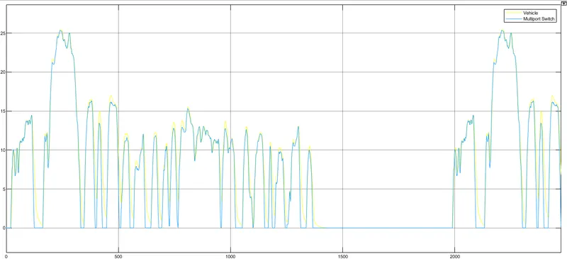
Before, i explain the each block. now operation of the model is 1st i choose the drive input for FTP 75 source its operated top speed of 25 m/sec. this signal going to driver.then driver fed to the signal for motor. so the output for the same as the vehicle output driving.
DRIVE CYCLE INPUT
VEHICLE OUPUT
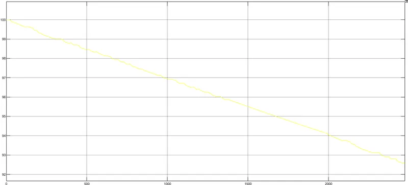
BATTERY % SOC
BATTERY AND MOTOR CURRENT
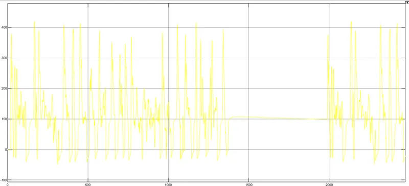
So, the all plots are plotted. the now changes vehicle mass, the battery soc and current also changes. the gear ratio changes the vehicle all parameter to changed.
RESULTS
|
DESCRIPTIONS |
CASE 1 |
CASE 2 |
CASE 3 |
CASE 4 |
|
Drive cycle, Distance, Top speed |
FTP75 25km 90 km/hr |
spreadsheet 30 km 110 km/hr |
Signal builder 25km 90 km/hr |
WLTP CLASS 3 61.4 km 130 km/hr |
|
Vehicle weight |
2000 |
2000 |
2000 |
2000 |
|
Frontal area, Drag co-efficient, Rolling resistance |
3 sq.m 0.25 0.015 |
3 sq.m 0.25 0.015 |
3 sq.m 0.25 0.015 |
3 sq.m 0.25 0.015 |
|
SOC at end of drive cycle (100% Initial) |
7.5 % |
5 % |
0.5 % |
8 % |
|
Top speed reached? |
yes |
yes |
yes |
yes |
So the above model the dc motor 50kw can be used for at rated speed was 7000RPM. the Driver control type is PI loop gain for tracking the reference speed.The battery discharge can be max of 8% . The various model library (simscape, simulink and powertrain block set.the simulation also fast due to neglect PWM controls.The simulation Time to depends on driver input.
CONCLUSION
In this project was developed by the battery operated to dc drives. For all are the assumptions value.motor consumed power 50kw and battery taking to 120 Ah in our project. this model can simple to control and also the easyway. so we are any technical data of the ev car design same consideration some of the values is to be changed and overall system literally change. this model maintain a gear ratio for 2. in way the gear ratio will be change entire system performance also changed. different drive cyycle source develop for understanding of the how many distance going to be travelled for an vehicle. The h-bridge converter provide control motor For an motoring and braking actions. the bridge voltage 300v.so the overall syatem simulation time is depends on the drive input.