Final Project: Design of an Electric Vehicle
Aim: To develop an Electric Vehicle model in Simulink Environment.
Study:
An Electric vehicle is a battery driven Vehicle unlike the commercial vehicle which is driven by Combustion engine.
The main components of Electric Vehicle are:
- Motor Controller
- Battery
- Vehicle Chasis
The Simulink Model of the Electric Vehicle is shown below:
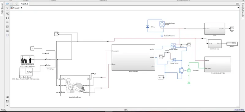
- At the left side of the model there is 1 switch. This switch choose the drivecycle of the vehicle. It can be given by the drivecycle block where there are some standard drive cycles are available or can be given manually. Here we choose the US06 drivecycle for our simulation.
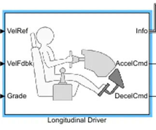
- Then there is a driver body block which acts as a driver. It is a PI controller block which takes the vehicle spped as a feedback and give the acceleration and brake output.
Motor Controller:
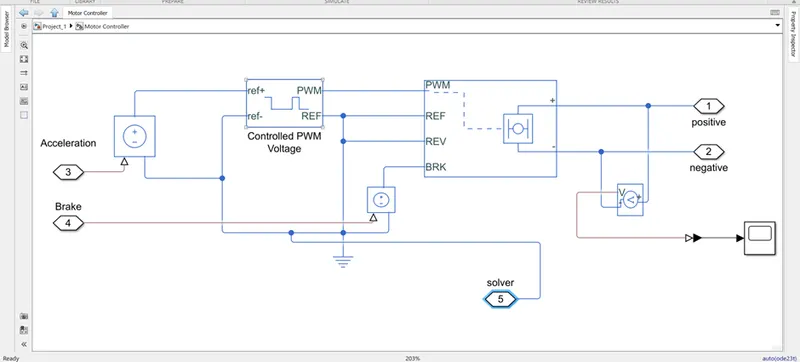
The motor chosen for our Electric vehicle is a DC motor. To control a DC a controlled PWM voltage is provided.
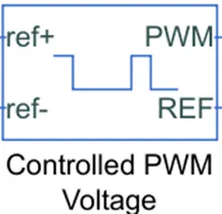
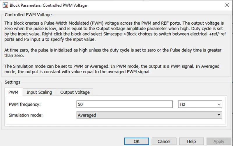
- A control voltage is used to give the input to the PWM, which is controlled by the driver block acceleration command.
- The output of the PWM is given to H-bridge.
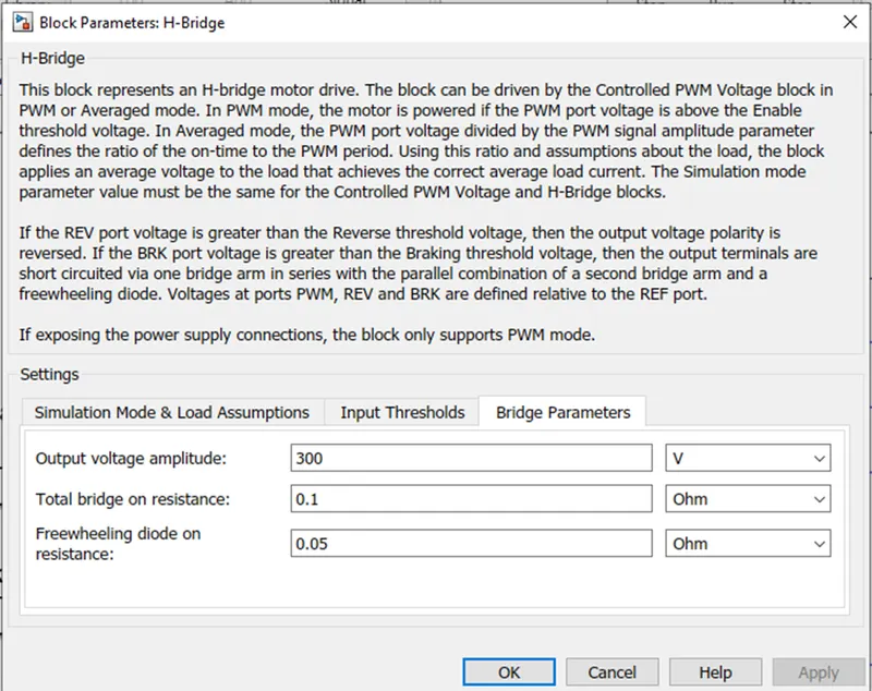
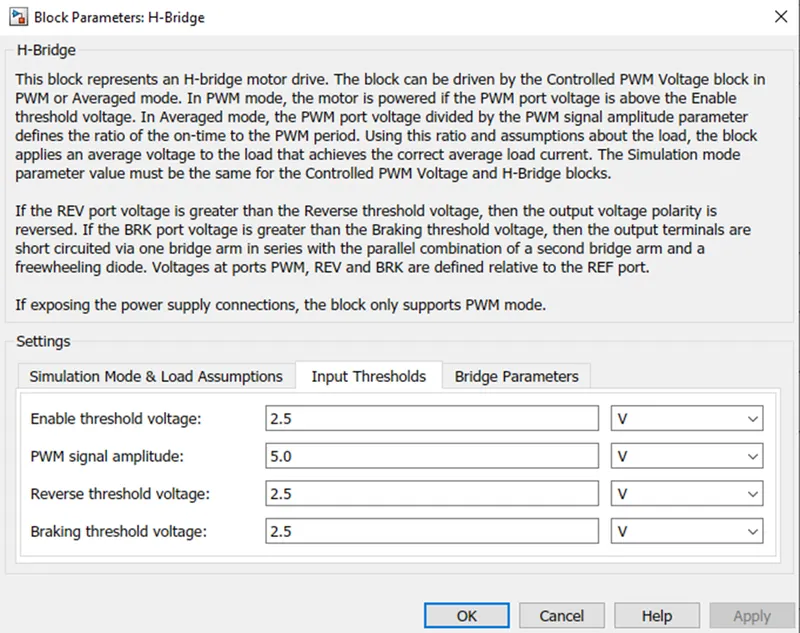
- The brake signal is given from the Controlled Voltage Source which is controlled by the Drive block.
- The Reverse (REV) Ref (REF) are all grounded.
- The output of the H-bridge is given to the DC motor through a current sensor.
- A Voltage sensor is connected at the terminals of the H-bridge. The output of the voltage sensor is shown below:
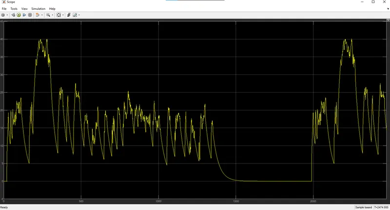
DC Motor:
A DC motor is used for our Electric Vehicle application.
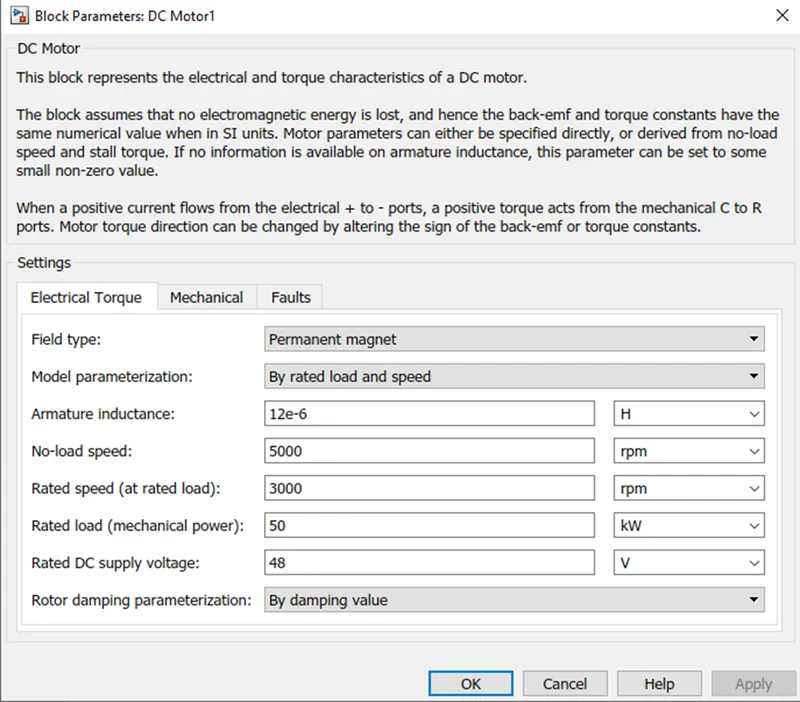
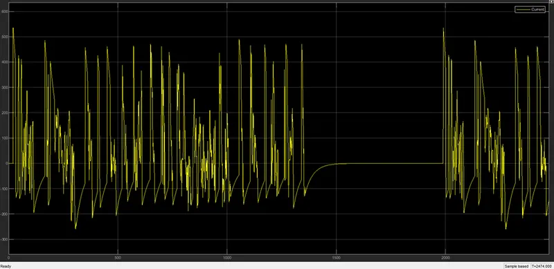
- A Current Sensor is connected to sense the current and this signal is given to the Controlled Current Source which is connected across a battery.
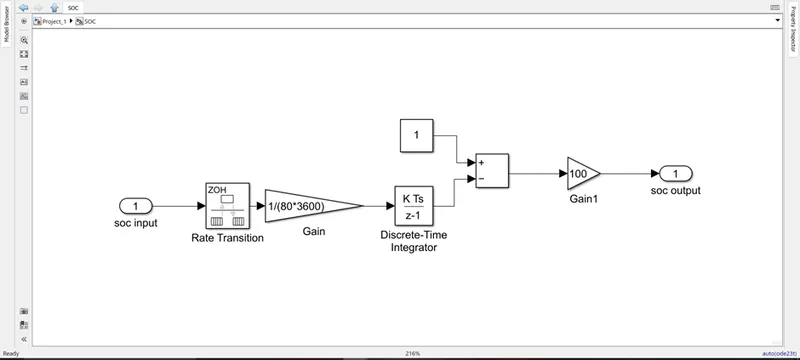
- This signal also helps us in calculating the SOC of the battery.
- This signal is changed to a Simulink signal and then given to a rate transition block.
- After this it is multiplied with a gain of 1/(80*3600) and passed through an discrete integrator.
- This is now subtracted from the value of 1 and then multiplied with 100 to get the SOC percentage.
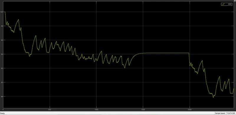
The SOC output is shown below:
Then the last part of the model that is the chasis (Vehicle Body).

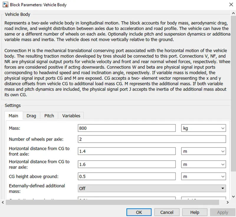
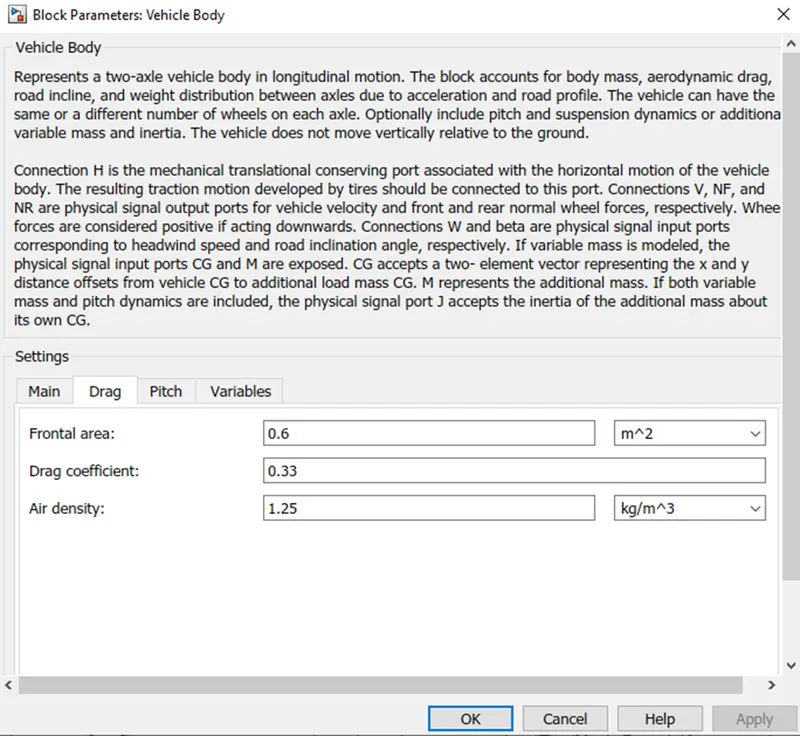
- A vehicle body block is used and 4 tires –Tire (Magic Formula) is used.
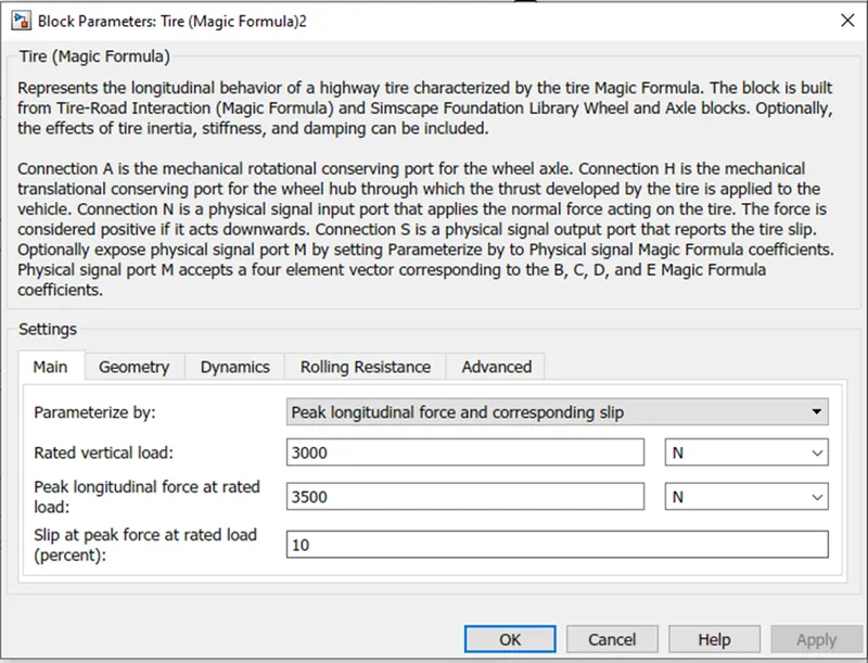
- The normal force port of the tire (N). This port is connect with the another tire N and same goes for other 2 tires. Now they are both connected to the NF and NR for front wheel and rear wheel respectively.
- The hub (H) of all tires are connected with each other and all are connected with the H port of the vehicle body.
- The Axle of the 2 front tires and rear tires are connected and a gear box is connected with the axle of both tire of the rear wheels.
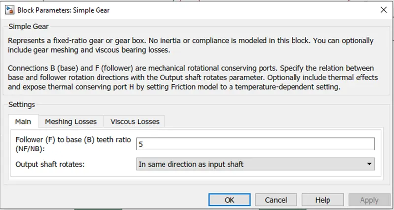
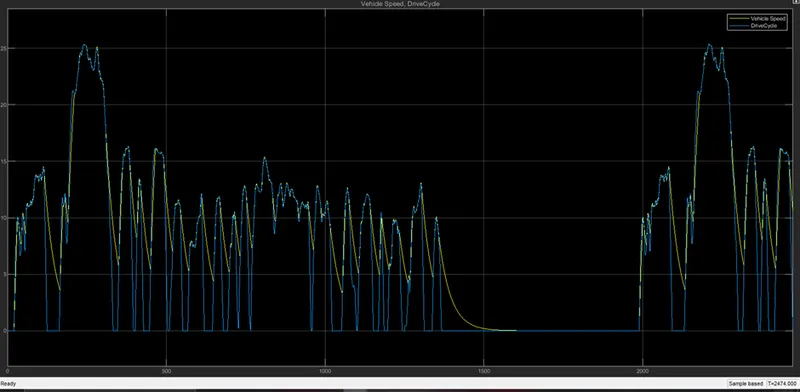
The Velocity (V) of the vehicle is determined by the V port of the vehicle body. This velocity is compared against the drivecycle to see whether the vehicle is following the drivecycle or not.
To calculate the distance
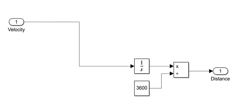
The velocity is integrated and is divided by 3600 to get the distance covered in Kms.
The speed of the vehicle is shown below:
Conclusion:
- We have seen the Vehicle is following the drivecycle. But for the steep braking the vehicle fails to put to a stop immediately.
- The SOC of the vehicle is 89.21%.
- The current characteristics shows there is regenerative braking happening in the system.