Final Project: Design of an Electric Vehicle
Aim: To design a MATLAB model of an electric vehicle which uses a battery and DC motor by using suitable blocks
Theory:
An electric car is propelled by using an electric motor which is operated by high efficiency and rechargeable battery packs. Electric vehicles are highly efficient and promote zero carbon. The motors used in an electric vehicle are either permanent magnet synchronous motors, 3 phase induction motors, or BLDC motors.
The battery packs used need to be highly efficient and durable. They are recharged by using inverters( AC-DC Conversion). DC chargers are used for fast charging.
Block diagram:
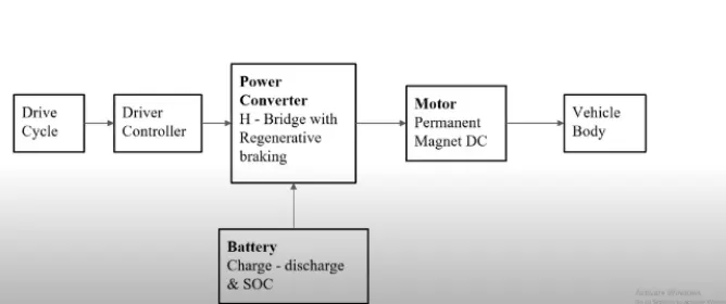
This is a typical block diagram of an electric vehicle. It contains a drive cycle that comprises the time and speed inputs. The driver controller consists of the driver inputs like acceleration and braking. The power converter consists of an H-bridge setup with regenerative braking to improve efficiency. The H-bridge setup is connected to the battery and the motor. The battery charge and discharge to the motor are controlled by the H-bridge setup. The motor that we're using here is a permanent magnet DC motor which is connected to the vehicle body.
Simulink Diagram:
Subsystems:
1. Drive cycle source:
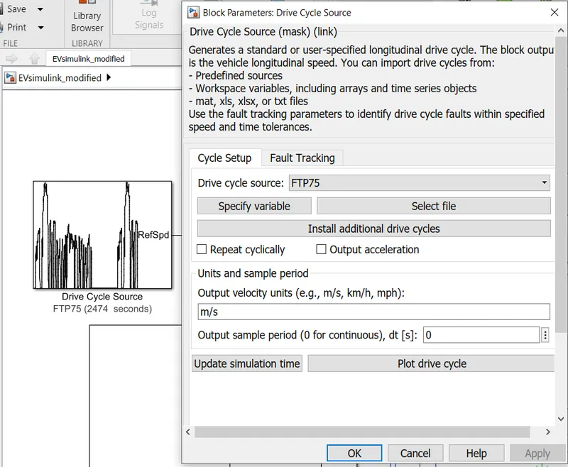
Here, we are using an FTP75 drive cycle source which is in-built in Simulink.
2. Longitudinal Driver:
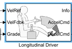
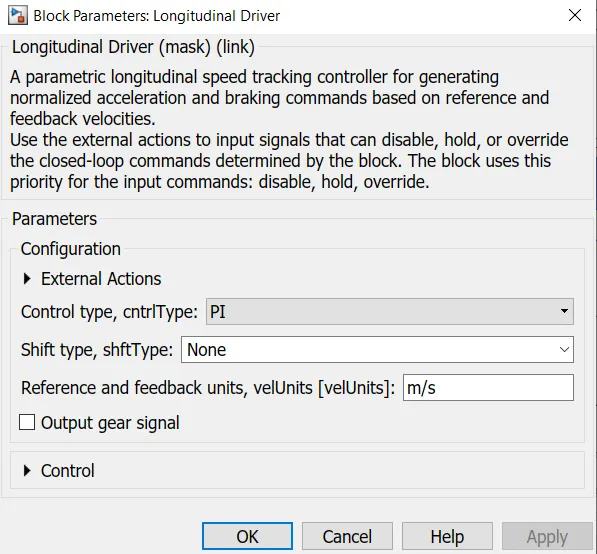
This depicts the driver block set which controls the acceleration and deceleration of the vehicle. Here, we are using a PI controller for the same.
Motor and controller:
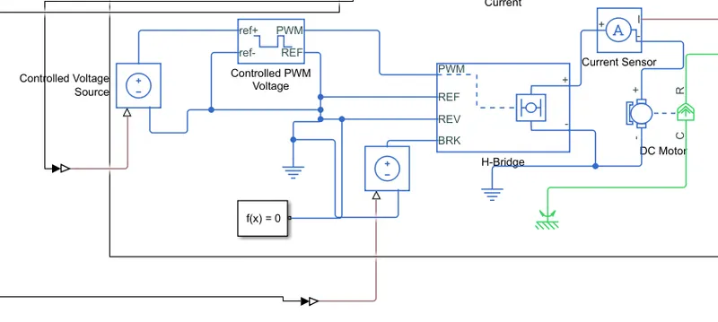
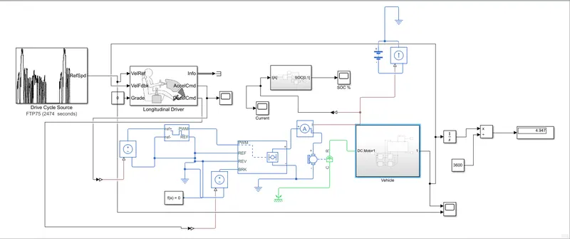
The power control unit subsystem contains blocks that are used to create the voltage signals to control the motor speed as per the input drive cycle data.
The controlled voltage source is connected to the PWM voltage and the H-bridge is connected to the acceleration and deceleration command.
These commands are converted into voltage signals by the voltage sources.
Controlled PWM voltage block:
The block creates the pulse width modulated voltage. The duty cycle is based on the reference voltage across ref+ and ref- ports. This modeling variant is the default.
The value of the output voltage amplitude parameter determines the amplitude of the output voltage.
H-bridge block:
This is used to change the polarity of the voltage applied across the DC motor to run the motor in a forward or reverse direction. It has simulation mode and loads assumptions like regenerative braking, power supply, load current characteristics.
We can enable a threshold voltage, either forward or reverse and input certain bridge parameters too like Output voltage amplitude, the total bridge on resistance, and freewheeling diode on resistance.
Current sensor block:
This is used to measure the current flowing through the H-bridge.
DC motor:
To convert electrical energy to mechanical energy, we use this motor. In the case of regenerative braking, this motor can act as a generator too.
The electrical torque and mechanical parameters of the motor can be altered. We can alter values like no-load speed, rated speed, rated load, rated DC supply voltage, no-load current, and DC supply voltage when measuring no-load current. Mechanical parameters that can be altered are rotor inertia and initial rotor speed.
Battery subsystem:
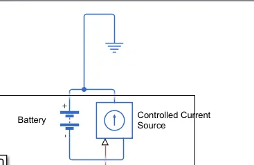
A simple battery source contains a series of internal resistance and a constant voltage source. The parameters of the battery can be altered according to our requirements.
Controlled current source:
This block gives a constant current output regardless of the voltage across it.
SOC subsystem:
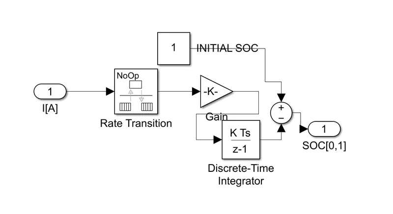
The input from the current sensor is sent to the rate transition block. This handles the transfer of data between blocks operating at different rates.
This is connected to the gain block which helps convert Ampere hour to Ampere second. We provide a gain value of 1/(100*3600)
This is then connected to a discrete-time integrator which accumulates the input signal. The summed value is subtracted from 1 and will give us the remaining SOC.
We then convert this to a percentage.
Vehicle body subsystem:
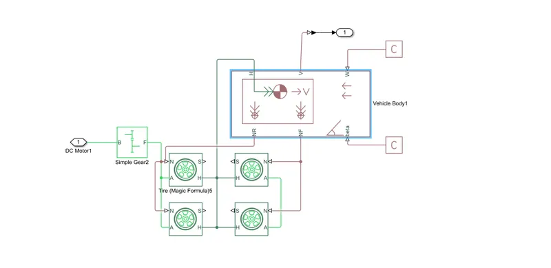
The input to this subsystem is the mechanical rotational port of the DC motor which is connected to a gearbox of gear ratio of 3.7
The simple gear is connected to 2 wheels which represents a Front-wheel drive. The tires are represented by using a magic formula block.
To represent the vehicle body block we have used the vehicle body block.
The front and rear normal forces are represented by NF and NR which are connected to the tires.
The H port is the mechanical translational conserving port for the wheel hub which is associated with the horizontal motion of a vehicle body.
To the gradient and wind speed ports of the vehicle body block, we have connected the physical signal constant block.
The velocity feedback input from the driver block is connected to the body block.
Results:
Scope 1:
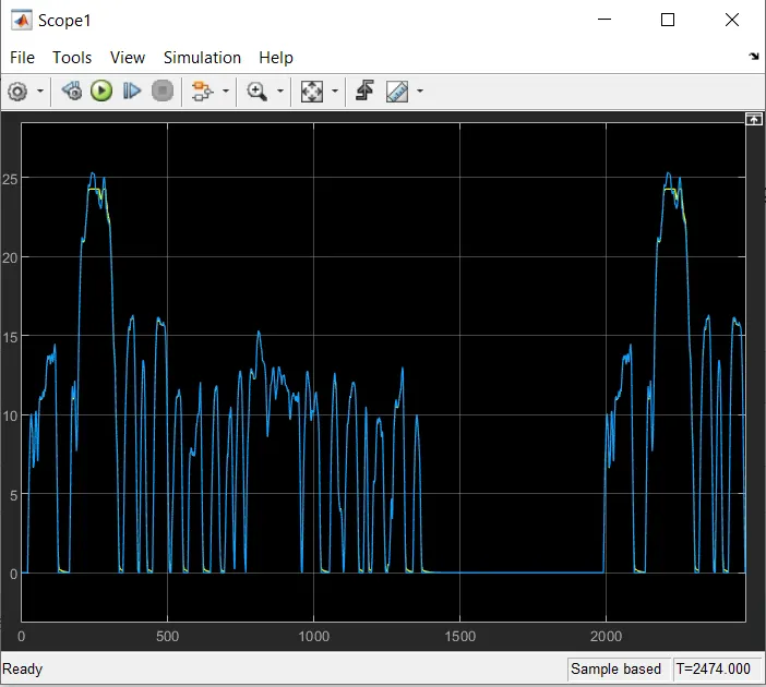
The results from Scope 1 indicate the velocity/time graph for the entire setup and the drive cycle source.
We can notice that both the graphs match each other which means that for the drive cycle source, the vehicle performs all the operations efficiently.
Scope connected to acceleration command:
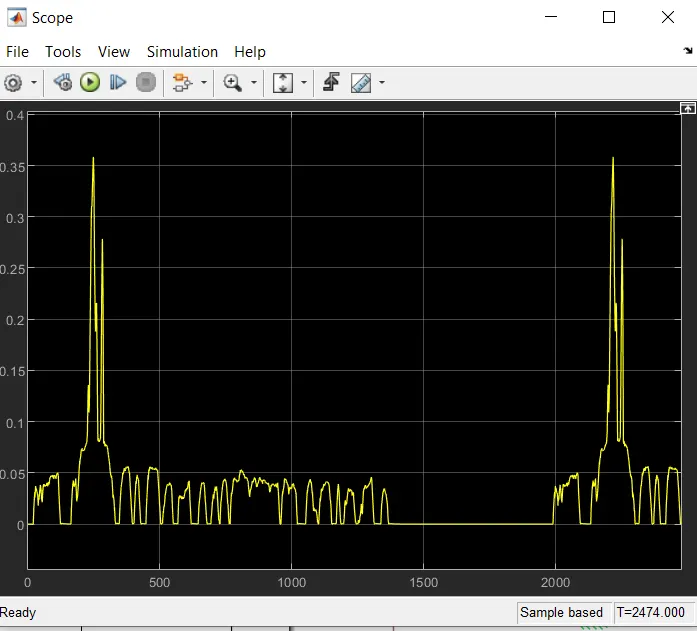
This represents the throttle responses and braking responses for the drive cycle.
Current scope:
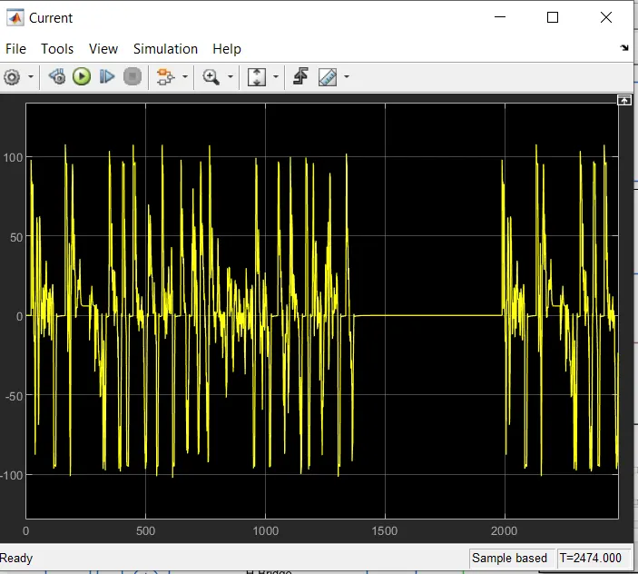
This scope represents the battery current discharge and charge based on the drive cycle.
SOC scope:
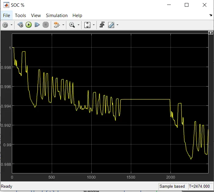
This scope represents the battery SOC discharge and charge(regen braking)
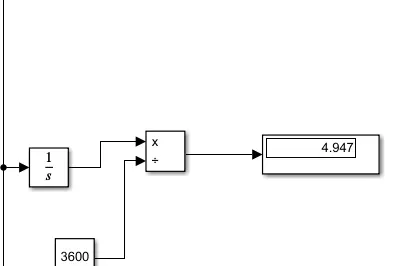
The display represents the total distance traveled in km/h.
Conclusion:
We have successfully simulated an electric vehicle on MatLab Simulink with the FTP75 drive cycle. From the SOC we can conclude that the battery has a very low capacity and is almost drained by the end of the drive cycle. The current value while driving is 100A and it drops to around 50A during regenerative braking. The total distance traveled is 4.9kmph which shows that the parameters are inefficient since we have not altered the values of the parameters too much.