Final Project: Design of an Electric Vehicle
Aim:
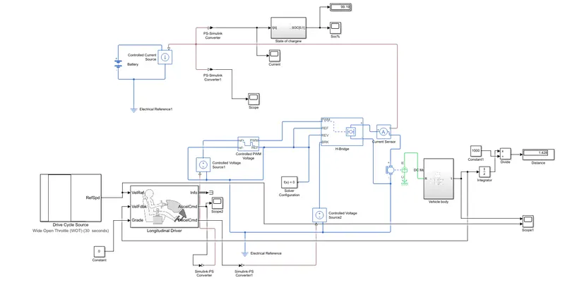
Create a MATLAB model for electric vehicle which uses a battery and DC motor.
Objective:
To create a model in simulink we need
The main components of a EV are:
1.Battery.
2.Power converters.
3.Motor/Generator controller.
4.Motor /Generator.
5.Transmission System.
6.Tyres/wheels.
Vehicle Body:
We need a vehicle body block to model the characteristics of vehicle body in to the Matlab.
There are six ports to characteristics the vehicle body.
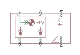
H:H stands for Hub to connect the hubs of the wheels to the main body of the vehicle.
V:It's an a physical signal output port to represent the velocity of the body and it will gives the speed/velocity for to identify at which speed the vehicle is moving.
W:Its an physical signal input port, and it will provides the model headwing action of the vehicle by giving a speed far of it.
NR:Physical Signal Outputport to the model rear wheels normal forces.
NF:Physical Signal Outputport to the model front wheels normal forces.
beta:its an ahill climbing angle of the vehicle i.e an inclination of the vehicle wheel.
Block parameter of the Vehicle body
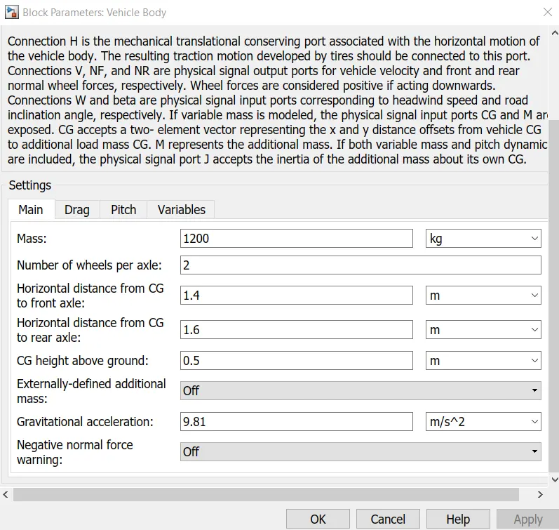
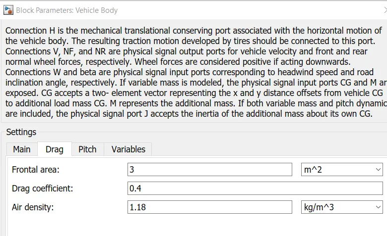
Now clicking on the drag parameter we can change the parameters value like drag co efficient,frontal area,...
Changing the parameters there will be a change in drag force i.e Fd
Let us leave them as default values..
Tires:
The tires used in the EV model are the magic formula tires.These are several tire blocks that can be used for modelling a vehicle but i have used the magic formula ones because it allows us to model the longitudinal behaviour of vehicle on highways.They also allow us to model extra effects such as tire inertia,stiffness which allow for greater accuracy of real world conditions.
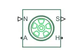
N :N is the normal and this physical signal ports is the input port for the normal force acting on the tire and is considered to be positive in the downward direction.
S: Slip,It is also an physical signal port it reports the slip acting on the tire.
A:Axle,its an a mechanical rotational conserving port for the wheel axle.
H:Hub,is an amechanical transational conserving port for the wheel hub through which the thrust developed by the tires is applied to the vehicle body.
Block parameter:
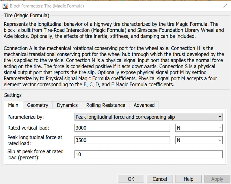
Take the default values from the block parameters as it is.
Slip:
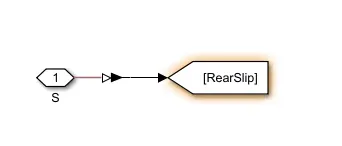
The S port on the LR and LF tires are modelled with a certain degree of slip using a small subsystem.This system uses a PS simulink converter will be used again later on for other systems in this EV model.The slip subsystem used for the magic formulae is shown in the image.
Gear:
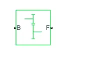
We used a simple gear block,so as to amplify the transmission related parmeters.The block model as a gear system with a fixed gear ration with no inertia effects however we can modify the effects of the meshing of gear teeth.The simple gear block shown below.
Side Shaft:
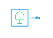
An inertia block as been added to the workspace to provide an ideal mechanical rotational inertia for the simple gear block.This block has only one mechanical rotational conserving port and the positive direction of the block is fromthe port to the reference port which would be the simple gear in thjis case.The inertia torque acts in the positive direction is the inertia is accelerated in the positive direction.
Velocity Subsystem:
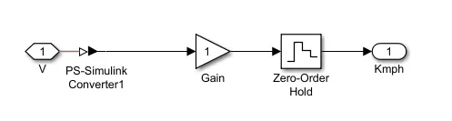
The velocity port which outputs the velocity signal of the vehicle body block has been modified.By default the velocity signal that is outputs fromthe vehicle body block is measured in miles per hour.To change these units i made subystem,in this subsystem
PS simulink converter it will converts the physical signal of velocity to a logic signal.
Gain,it will multiply with 1.610 converts the miles per hour to kilometer per hour.
Zero_Order_Holdit will implements a zero order hold sample period,
Subsystem block as shown below:
Vehical Body:
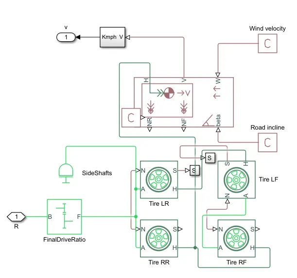
From the above we can see the connections for the vehicle body.
In this we have four magic formula tire blocks are used as the vehicle will have 4 tires,2 on each axle.The tires we have LE,LR,RE,RR(left rearleft front,right rear right front).The normal ports of each tire are connected to the appropriate NR and NF ports on the vehicle body.The hubs of each tire are connected together and an extra connections is made from them to the vehicle body block.The S port of the LR and LF1 tires have been modelled with a slip using a small subsystem.The simple gear and inertia blocks are connected to the axle port of the tires.The wind velocity and road incline are provided with the PS constant blocks of 5mvs and o degree.The velocity port has been connected to the velocity subsystem and the connection from the subsysytem is open to the V port.The base port of the simple gear has been left open to the R port to take in a rotational signal.After these made a subsystem.
Motor:
Motor for EV model,DC motor bock used as the motor.
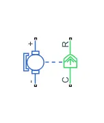
There are 2 sides to the block the mechanical side on the right and the electrical side on the left.The mechanical side has 2 parts C and R.The C refers to the casing and the R refers to the rotation of the rotor which produces a torque.The electrical side has a positive and a negative terminal for the voltages to be applied.If a positive voltage is applied to the DC motor block from the positive to the negative terminal ,a positive torque will act from the C port to the R Port.The direction of the torque produced by the DC motor can be changed by the changing the sign of the back emf ,the torque constant.The C port of the mechanical side to be connected to a mechanical rotational reference because it will be stationary.The R port will be connected to the open connection of the simple gear from the vehicle body block.The positive terminal on the electrical side connected to the positive terminal of a power converter which in my case will be an H bridge.
Mechanical rotational reference block:

Power Converter:
The power converter is neede to provided power of the correct form and magnitude from one component to another.In the case of EV ,power converter is needed 10 provide a DC voltage from the battery of the EV to the DC motor.So that it can operate property with the required parameters.H bridge motor drive as my power converter.
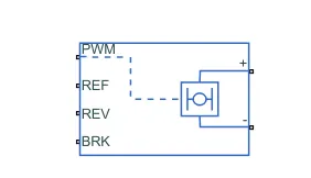
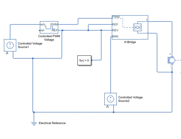
H bridge,2 sides to its left side is for the controlling of the voltage signals and the right side,it is for the terminals to provide the controlled voltage to the DC motor.The left side ports of the H Bridge block are
PWM-Pulse width modulation which will provide the voltage pulses to the H-Bridge either in the PWM or average mode.
REF-Reference
REV-Reverse
BRK-Brake
Controlled PWM voltage:
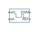
It will provide a controlled pulse width modulated voltage to the H bridge block.The block will be output the PWM voltage through its PWM and REF ports which will feed in to the same port found on the H bridge block.If the pulse is low ouput voltage is considered V whereas if the pulse is high,the output voltage will be equal to the output voltage amplitude which was set to 330V in the H bridge block.The pulse of voltage created by this block are dependent on the duty cycle which is the ratio of the time ,that the switch is ON 10 the time taken for 1 cycle.The duty cycle is set by the input of the controlled PWM voltage block.
Controlled Voltage Source:
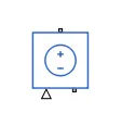
The input ports of the controlled PWM voltage block are still unconnected and that is because they require a voltage pulses to be fed in to the HBridge,since i took controlled voltage source block.It will maintain the voltage at the output regardless of the current passes through it.
Longitudinal driver:
This block implements an a longitudinal speed tracking controller.Based on refernce and feedback,the block generates normalised acceleration and braking commands that vary from 0 to 1.
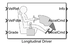
VelRef:reference velocity,this data is given from the drive cycle.
VelFdbk:Feedback velocity,this data is given by vehicle body and gives outputs to the velocity data.
Grade:It gives an inclination angle for the surface on which the vehicle is travelling.
Info:it contains the information about the bus signal i.e acceleration,decceleration command differ between reference and vehicle speed.
AccelCmd:It gives the acceleration command to the controlled voltage source.
DecelCmd:It gives the deceleration command to the controlled voltage source.
The refernce velocity data coming to the drive cycle source is compared to the feedback velocity data coming from the vehicle body block.If the reference velocity is greater than the feedback velocity an acceleration command is output or If the reference velocity is lesser than the feedback velocity an decceleration command is output which is given to the controlled voltage source.at the ouput we have connected a pS converter.
Drive cycle source:
It has a data set contains a time and velocity for the modelling of the vehicle.Here we used a UDDS FTP75 drive cycle.
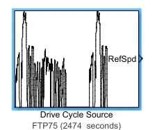
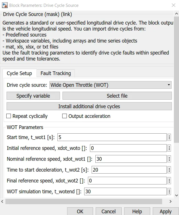
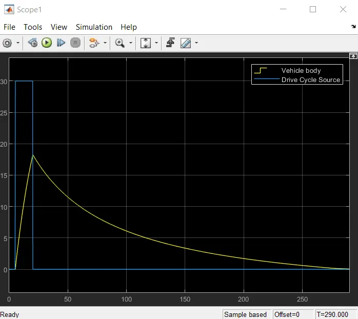
In this model,we drive cycle is used as the reference data for the longitudinal driver block to send accleration or decceleration commands according to the drive cycle,here we took a industry standard drive cycle which are built in to the simulink library.in this drive cycle stands for wide open throttle and a models the situation where the vehicle is made to accelerate at ful power and maintained ata particular speed and made to deccelerate back to rest.
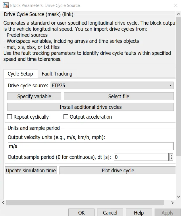
For Wide Open Throttle condition:
Battery Source:
The battery is connected to the power source of the model,so the power could be generated and the same power is also transmitted.
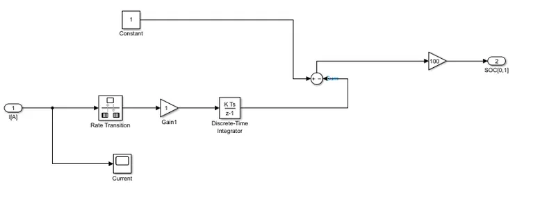
Soc estimates:
The complete EV model:
This graph indicates the drive cycle depends on the velocity of the vehicle.
This graph is SOC, as the time increases SOC goes on decreasing
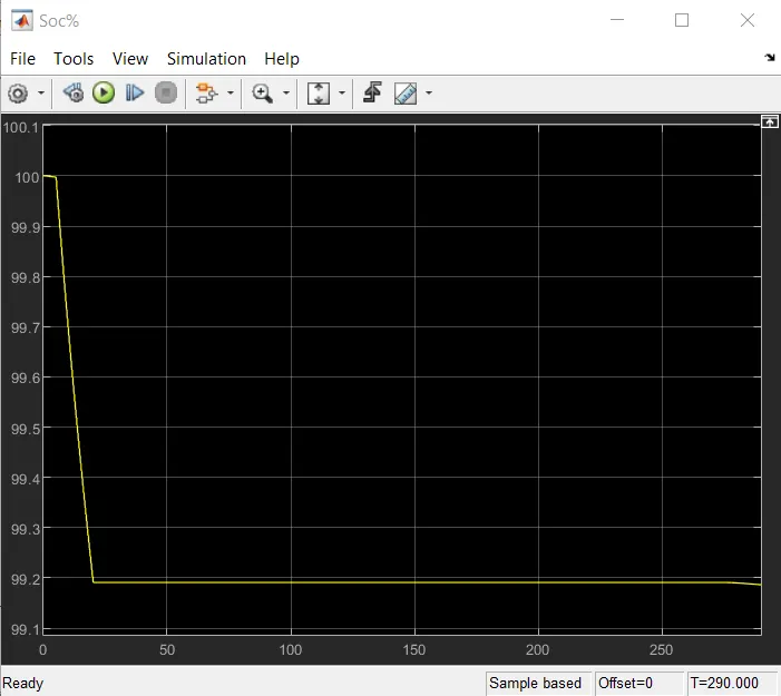
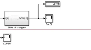
From the above blocks we know that the SOC has 99.19%
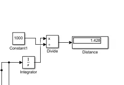
The distance covered is 1.428kmph for 295 sec
Conclusion:
In this EV model has been created with simulink.By taking a WOT 30sec condition for Drive cycle FTP575.The simulation has produced the results of vehicle velocity with respect to the acceleration and the current flowing through the SOC and covered a distance of 1.428kmph in WOT(30 sec) with having 99.19% SOC.