Design of Electric Vehicle
ELECTRIC CAR MODEL USING BATTERY AND DC MOTOR
Aim: To create a Matlab model of electric car using battery and DC motor by using the powertrain blockset blcoks.
Objectives:
- System level configurations
- Model parameters
- Results
- Conclusion
General theory:
Electric cars are reffered as battery driven cars, which have a motor instead of a internal combustion engine. The vehicle uses a large traction battery pack to power the electric motor and must be plugged in to a wall outlet or charging equipment known as electric vehicle supply equipment (EVSE). Since it uses electric power to run their will bezero emission from the vehicle. DC-DC converters used for power conversion needed to run vehicle accessories and recharge the auxiliary battery. In order to control the flow of the electric energy which inturn controls the speed and torque of the motor by using the Power-Electronic converters.
Motors:
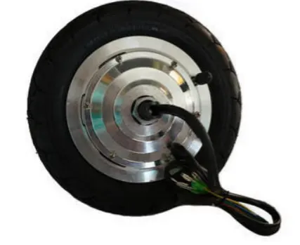
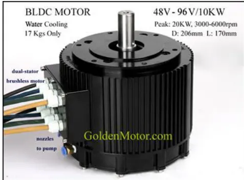
BLDC Out-runner type BLDC In-runner type
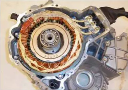
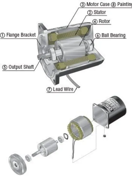
Permanent-magent Synchronous motor Three phase Induction motor
Main Model:
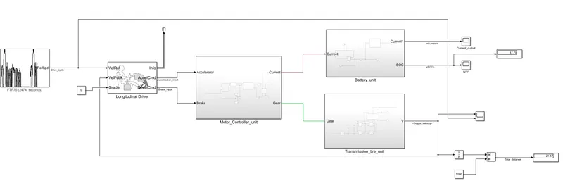
- Lets deep dive learn about each block used and its importance in the model.
1) Drive cycle:
A driving cycle is a series of data points representing the speed of a vehicle versus time. Driving cycles are produced by different countries and organizations to assess the performance of vehicles in various ways as for instance fuel consumption, electric vehicle autonomy and polluting emissions.
- In this case we used a FTP75 driving cycle.
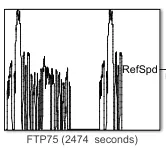
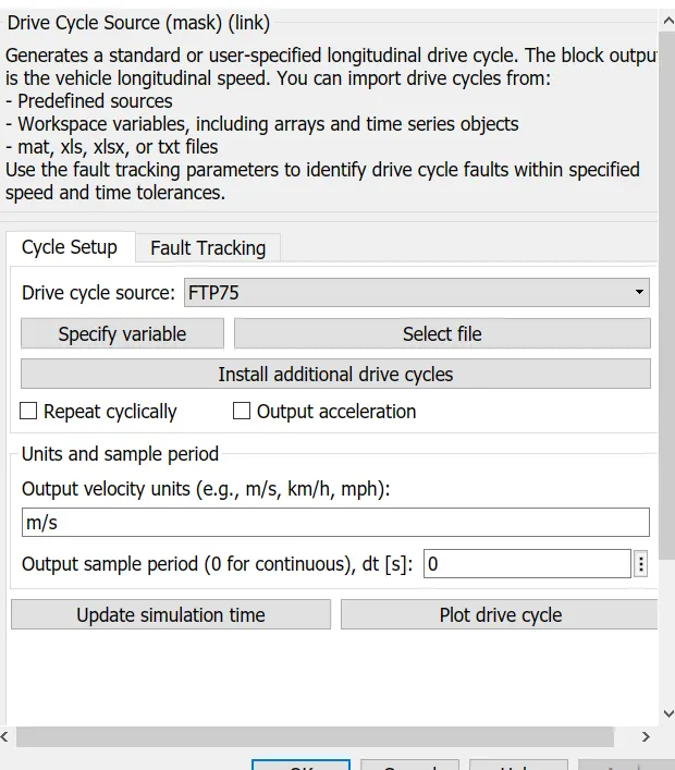
- This blcok will help us in inputting the drive cycle data it can be either by standard drive cycle or by using WOT input or by inputting data in excel sheet and updating the sheet values to the model.
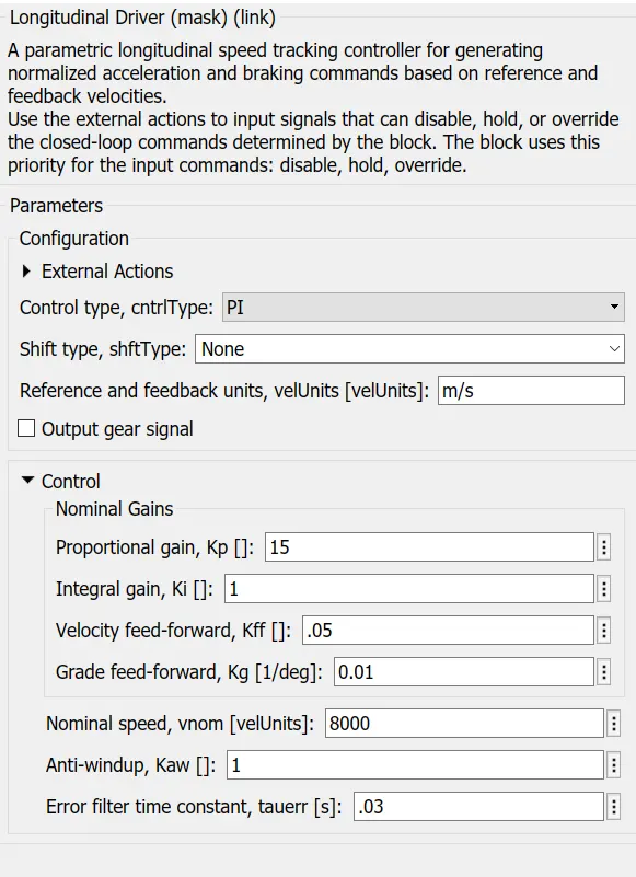
2) Longitudinal Driver:
The Longitudinal Driver block implements a longitudinal speed-tracking controller. Based on reference and feedback velocities, the block generates normalized acceleration and braking commands that can vary from 0 through 1. You can use the block to model the dynamic response of a driver or to generate the commands necessary to track a longitudinal drive cycle.
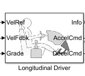
- Longitudinal parameters are speciifed as below.
3) Motor and Controller subsystem:
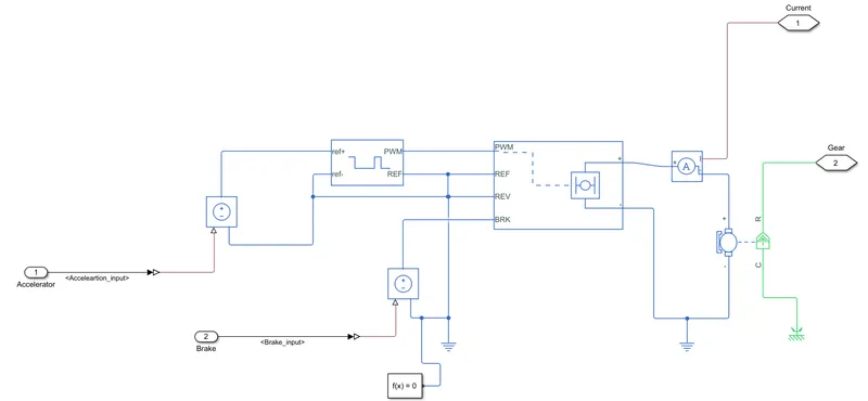
- Controller and Motor subsystem has block which is used to create the voltage signals to control the motor speed which in turn controls the speed of the vehicle as per the input drive cycle.
- The output from the longitudinal driver block of acceleration and deceleration commands are given as inputs to these block.
- In this the acceleration command and deceleration command into voltage signals using controlled voltage source, controlled voltage source, PWM controlled source, H-bridge and current sensoor to sense the current and in this current output is given as input to motor on which the shaft of the motor will be rotating. The speed of the motor is dependent on the current comming from the H-bridge.
- Controlled Voltage Source:
-
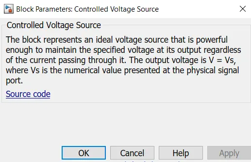
The Controlled Voltage Source block represents an ideal voltage source that is powerful enough to maintain the specified voltage at its output regardless of the current flowing through the source. The output voltage is V = Vs, where Vs is the numerical value presented at the physical signal port.
Parameters of the block:
- Controlled PWM voltage:
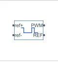
- The Controlled PWM Voltage block represents a pulse-width modulated (PWM) voltage source.
- Electrical input ports — The block calculates the duty cycle based on the reference voltage across its ref+ and ref- ports. This modeling variant is the default.
- PS input — Specify the duty cycle value directly by using an input physical signal port.
- The value of the Output voltage amplitude parameter determines amplitude of the output voltage.
- Below are parameters specified for the PWM block.
u — Control signal, unitless, physical signal: Input physical signal that specifies the duty cycle.
ref+ — Positive terminal, electrical: Positive electrical reference voltage.
ref- — Negative terminal, electrical: Negative electrical reference voltage
PWM — Pulse-width modulated signal, electrical: Electrical conserving port associated with the pulse-width modulated signal.
REF — Floating zero volt reference, electrical: Electrical conserving port associated with the floating zero volt reference.
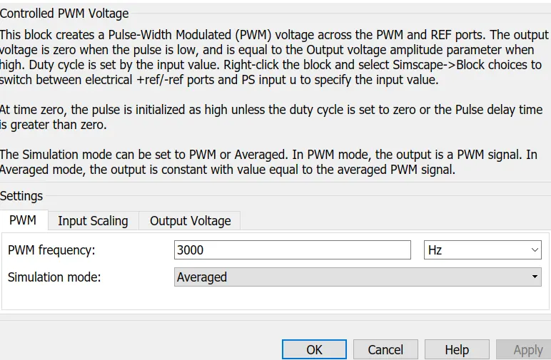
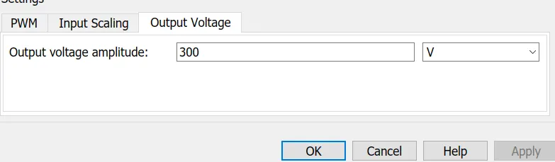
- This block sends the controlled voltages to the H-bridge.
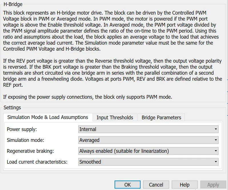
- H-Bridge:
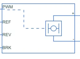
- An H-Bridge block is used in to maintain the run of the motor in both forward and reverse direction which is done by the polarity change of the voltage supplied to the motor.
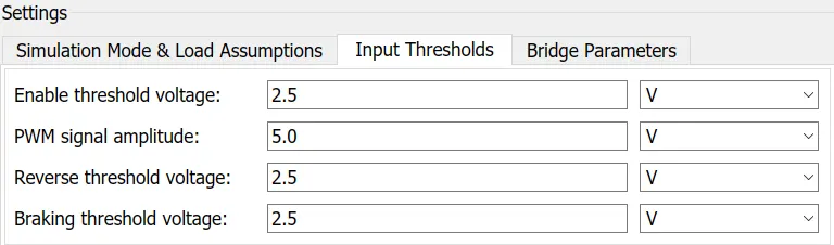
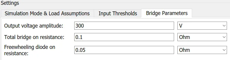
- Below are considered parametes in this model for H-bridge.
+ — Positive load connection port, electrical: Electrical conserving port associated with the positive load connection.
- — Negative load connection port, electrical: Electrical conserving port associated with the negative load connection.
V+ — Positive supply connection, electrical: Electrical conserving port associated with the positive electrical supply connection.
V- — Negative supply connection, electrical: Electrical conserving port associated with the negative electrical supply connection.
PWM — Pulse-width modulated signal, electrical: Electrical conserving port associated with the pulse-width modulated signal. The voltage is defined relative to the REF port.
REV — REV, electrical: Electrical conserving port associated with the voltage that controls when to reverse the polarity of the H-Bridge block output.
BRK — BRK, electrical: Electrical conserving port associated with the voltage that controls when to short circuit the H-Bridge block output.
- The controlled output of the H-bridge is given as input to the DC motor in between we have kept a current sensor in order to measure the current flowing and also to estimation of SOC battery this current is used as input.
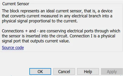
- Current Sensor:

- This block converts current measured in any electrical branch into a physical signal proportional to the current.
+ - Electrical conserving port associated with the sensor positive terminal.
- Electrical conserving port associated with the sensor negative terminal.
I - Physical signal output port for current.
- The output from the PWM is given to DC motor.
- DC MOTOR:
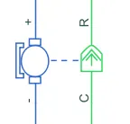
- The DC Motor block represents the electrical and torque characteristics of a DC motor.
- Motors are used to convert electrical to mechanical conservations. In this we have used DC motor which has both forward and regenerative breaking modes of operation. In regenerative breaking the motor acts as a generator.
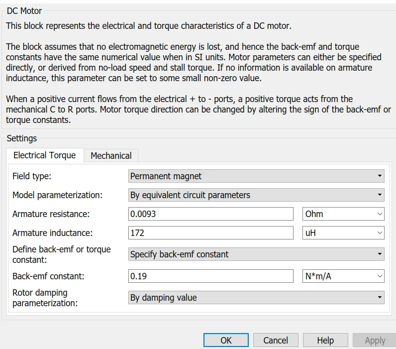
- Below are parameters specified for the DC motor used.
+ — Positive terminal, electrical: Electrical conserving port associated with the DC motor positive terminal.
- — Negative terminal, electrical: Electrical conserving port associated with the DC motor negative terminal.
C — Motor case, mechanical: Mechanical rotational conserving port associated with the DC motor case.
R — Motor rotor, mechanical: Mechanical rotational conserving port associated with the DC motor rotor.

- The output from the motor is given to the transmission and tire sbusysytem as input.
- The output from the current sensor is given as input to SOC subsystem.
- Electrical Reference:

- The Electrical Reference block represents an electrical ground. Electrical conserving ports of all the blocks that are directly connected to ground must be connected to an Electrical Reference block.
- Mechanical Rotational Refereence:

- The Mechanical Rotational Reference block represents a reference point, or frame, for all mechanical rotational ports. All rotational ports that are rigidly clamped to the frame (ground) must be connected to a Mechanical Rotational Reference block.
4) Battery unit subsystem:
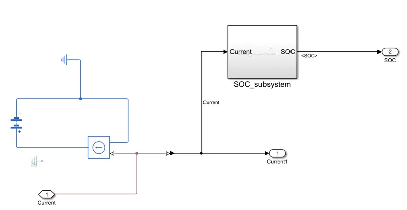
- The battery unit is used to determine the SOC of the battery which accepts the current as a input.
- It includes different components to estimate the SOC of the battery. Lets see each block and view its parameters.
- Battery:

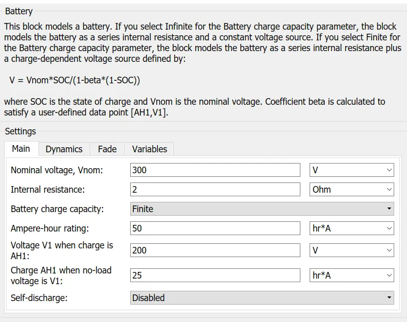
- A battery is a source of electric power consisting of one or more electrochemical cells with external connections for powering electrical devices.
- Battery parameters for this model is as given below
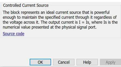
- Controlled current source:
- This block represents an ideal current source that maintains the specified current through it regardless of the voltage across it.
- The output current is I = Is, where Is is the numerical value presented at the physical signal port.
- In the battery unit we another subsystem i.e SOC subsystem in which the estimation of SOC model is modelled.
- SOC subsystem:
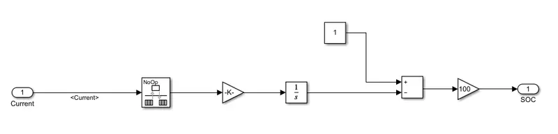
- In this we model the SOC estimation is done by using different which accepts the input data transitions and conversion into the Amphere.sec for the estimation. Since the battery initial condition will be 100% so the amount of eneergy ustilized is deducted to see the remaining battery charge so that estimation of the next drive cycle can be done.
Different blocks in SOC are:
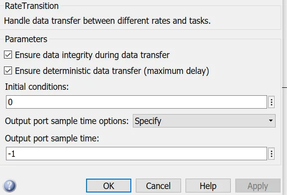
- Rate transition:

- The Rate Transition block transfers data from the output of a block operating at one rate to the input of a block operating at a different rate.
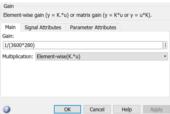
- Gain:

- The block is used to convert into 1/A.sec into A.hours
- Integrator:

- The Integrator block outputs the value of the integral of its input signal with respect to time.
- It collects all the input data of the time and it based on the input data sum up all the inputs and gives the output.
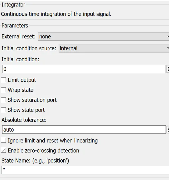
- The output of the gain is given as input to the subtract block where the initial condition of battery in our case is 100% and the used battery is deducted so the remaining battery eneergy can be displayed so that the estimation of next journey can be decided.
- From the battery unit we take output of the SOC and current which is taken from the H-bridge output to view about their behaviour.
5) Transmission and tire subsystem:
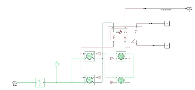
- In this the output from the motor is given as input to the gear which controls the tires and vehicle body movement of the car.
- From the input of the gear the vehicle speed will be controlled which is the output of the model for the applied input.
- It uses different blocks fro the conversion of input from the motor to the output of the vehicle as speed.
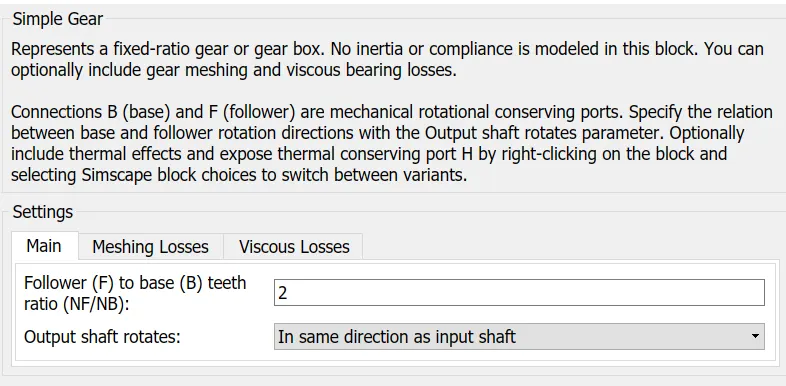
- Simple gear:
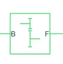
- The Simple Gear block represents a gearbox that constrains the connected driveline axes of the base gear, B, and the follower gear, F, to corotate with a fixed ratio that we specify.
- We choose whether the follower axis rotates in the same or opposite direction as the base axis.
- If they rotate in the same direction, the angular velocity of the follower, ωF, and the angular velocity of the base, ωB, have the same sign. If they rotate in opposite directions, ωF and ωB have opposite signs.
- Tire:

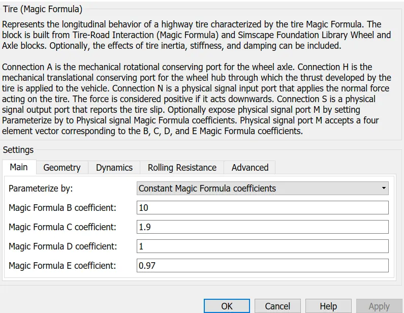
- The Tire (Magic Formula) block models a tire with longitudinal behavior given by the Magic Formula, an empirical equation based on four fitting coefficients and can model tire dynamics under constant or variable pavement conditions.
- To increase the fidelity of the tire model, you can specify properties such as tire compliance, inertia, and rolling resistance. However, these properties increase the complexity of the tire model and can slow down simulation. Consider ignoring tire compliance and inertia if simulating the model in real time or if preparing the model for hardware-in-the-loop (HIL) simulation.
N — Normal force, physical signal: Physical signal input port associated with the normal force acting on the tire. The normal force is positive if it acts downward on the tire, pressing it against the pavement.
M — Magic formula coefficients, physical signal | vector | [B, C, D, E]: Physical signal input port associated with the Magic Formula coefficients. Provide the Magic Formula coefficients as a four-element vector, specified in the order [B, C, D, E].
S — Slip, physical signal: Physical signal output port associated with the relative slip between the tire and road.
A — Axle, mechanical rotational: Mechanical rotational port associated with the axle that the tire sits on.
H — Hub, mechanical translational: Mechanical translational port associated with the wheel hub that transmits the thrust generated by the tire to the remainder of the vehicle.
- Vehicle body:
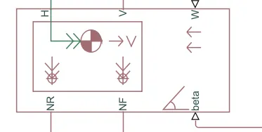
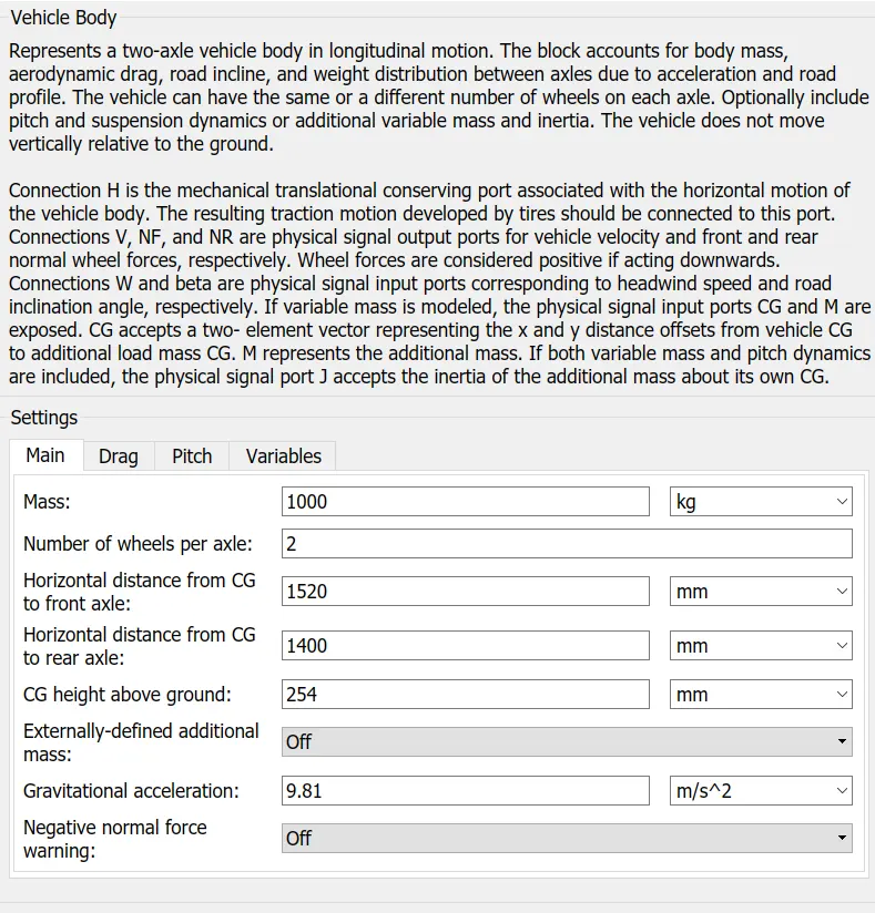
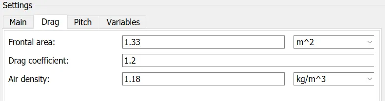
- The Vehicle Body block represents a two-axle vehicle body in longitudinal motion. The vehicle can have the same or a different number of wheels on each axle.
- The block accounts for body mass, aerodynamic drag, road incline, and weight distribution between axles due to acceleration and road profile. Optionally include pitch and suspension dynamics. The vehicle does not move vertically relative to the ground.
- The block has an option to include an externally-defined mass and an externally-defined inertia. The mass, inertia, and center of gravity of the vehicle body can vary over the course of simulation in response to system changes.
W — Headwind speed, m/s, scalar: Physical signal input port for headwind speed.
beta — Road incline angle, rad, scalar: Physical signal input port for road incline angle.
CG — Center of gravity, m, two-element vector: Physical signal input port for the center of gravity, in m, of the externally-defined mass relative to the CG of the vehicle body.
M — Mass, kg, scalar: Physical signal input port for the mass, in kg, of the externally-defined mass.
J — External moment of inertia, kg*m^2, scalar: Physical signal input port for the moment of inertia, in kg*m^2, of the externally-defined mass.
V — Longitudinal velocity, m/s, scalar: Physical signal output port for vehicle longitudinal velocity.
NF — Front axle normal force, N, scalar: Physical signal output port for normal force on the front axle. Wheel forces are considered positive if acting downwards.
NR — Rear axle normal force, N, scalar: Physical signal output port for normal force on the rear axle. Wheel forces are considered positive if acting downwards.
H — Horizontal motion, mechanical translational: Conserving port associated with the horizontal motion of the vehicle body. Connect tire traction motion to this port.
- The output from the Transmission and tire unit is vehicle speed which is fed back again to the speed feedback of the longitudinal driver block and also connected to the scope to view the output speed variations.
- Lets also create a model to estimate the total sitance travelled in the drive cycle.
- By using a integrator block to sum up all the velocities from start to final consition and is divided by 1000 in order to convert from m to km and finllay by using a diaplay blcok we can view the total distance travelled in the drive cycle.
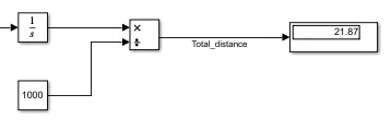
- Hence model is exaplained component to component lets take a look on the outputs of the model.
- Since the FTP75 drive cycle has 2474sec of time lets run the model for 2500sec.
Outputs :
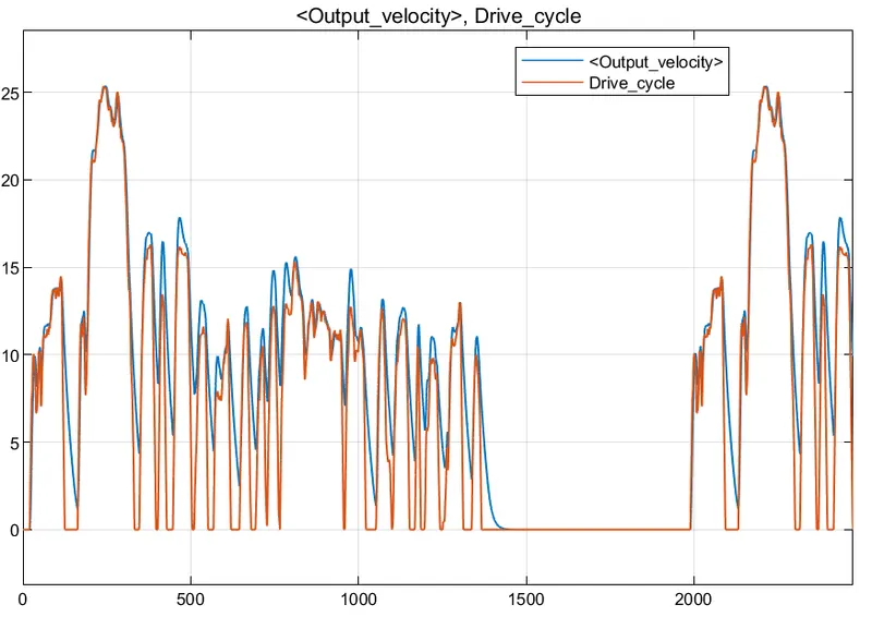
- In the scope we have input drive cycle and Output speed comaprisions, here the outputs almost traces the input but only when the input drops to zero in FTP cycle, the output takes time to catch the input. For all other conditions the output traces the input.
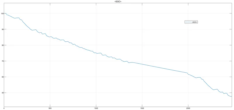
- The change in the State of Charge SOC is plotted we can see that the almost 53% of the battery is used for this drive cycle. In the plot we can see sometime their is slight incresing which shows that battery charge increases due to regenrative breaking.
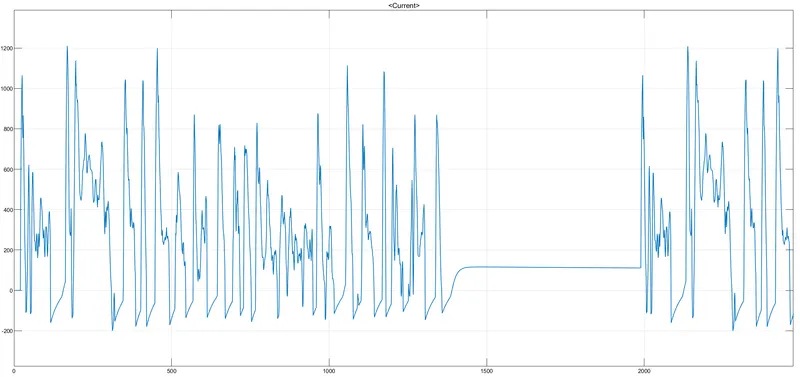
- This scope shows the variations of current during the drive cycle.
- Finally we can see the total distance travelled in the journey is around 21.87km though according to the FTP model its 17.77kms comparing with it their is difference but its close enough to comapre the model, showing that model is accurate in the following drive cycle.
Conclusion: Hence modelled a electric car using the battery and dc motor from the powertrain blockset of Simulink library.
Total distance covered = 21.87kms
SOC = 47.79% after the drive.