Final Project: Design of an Electric Vehicle
Final project( Modelling an Electric Vehicle)
Aim:
To model an electric vehicle with a battery,a DC motor,with their converter and controller using simulink and powertrain blockset .Verify the controlled vehicle velocities result with a referance drive cycle velocities.
Components used:
(1)Drive cycle source block(FTP75).
(2)Longitudinal driver block.
(3)Motor & Control(Subsystem).
- Controllrd voltage source.
- Controlled PWM Voltage.
- H-Bridge.
- DC Motor(Brush type).
- Current sensor.
- Voltage sensor.
- Ideal rotational motion sensor.
- Controlled current source.
- Battery.
- SOC unit.
- Solver configuration.
(4)Vehicle body.
- Tire.
- Vehicle body.
- Simple gear.
(5)Additionals.
- Powergui(Continuous).
- Scope
- Display
- PS-Simulink converter.
- Simulink-PS converter.
- Constant.
- Integrator.
- Product.
- Sum.
- Discrete time integrator.
- Rate transition.
- Gain.
- In ports,Out ports.
Model:
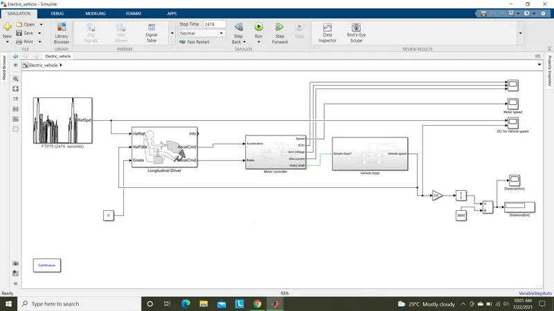
Below shown the overall model of the EV.
Motor and control unit:
Vehicle body:
Configuring block parameters:
(1)Drive cycle source.
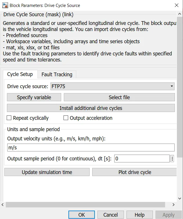
Here in this block we can feed any drive cycle data by our creation or configuring builtin drive cycles.This drive cycle data is given as referance to our motor control system.
They can be feed by excel data source,text files,mat files.In this we can change the output velocity unit as the model parameters.We can see the plots before simulating by clicking plot drive cycles.Changing sample period also possible in this parameter block,by default it is 0 for continuous simulation type.
We can also install additional drive cycles for our simulation test purposes.Fault tracking can be used when tracing out the faults in drive cycle.
Here for our simulation we are using FTP75 drive cycle.
(2)Longitudional driver block.
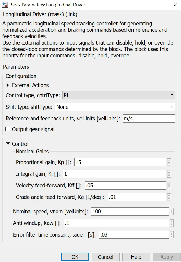
We are seeing the default longitudinal driver block parameters.This block is mainly used to compare the referance speed with the feedback velocities to give normalized accelerating and breaking commands.
This works under the PI control mechanism.We can change to sheduled PI and predictive type control.This block works by the operations of disable while breaking,hold while in constant speed and override when acceleration.
By default we are using PI control type and all its control values default.
(3)Motor and Controls.
(a)Controlled Voltage source:
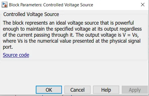
This block with produce variable voltages corresponding to the pulse signals given to it.The voltage level will be less while low values of signals are given.
For high value signals produces a high voltage level as source.
Rather than given out a constant voltage like battery sources, we can use this as modified voltage source.
For our model the driven commands are given as pulse signals.
(b)Controlled PWM voltage:
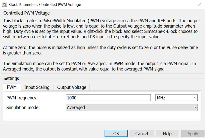
This block is used to convert the controlled voltage source to Controlled PWM voltage pulses. We have to set the pwm frequency and simulation mode type(Average or PWM mode).
In input scaling tab we have to set the duty cycle voltages from 0 to 100%.In output voltage tab we have to give voltage amplitude level for ON condition.
In OFF condition output voltage will be 0V.
For our model we choose 1000Mhz as pwm frequency,simulation mode as averaged.Duty cycle voltage varies from 0 to 0.5V from 0 to 100%.
Output voltage amplite as 5V.
(c)H-Bridge:
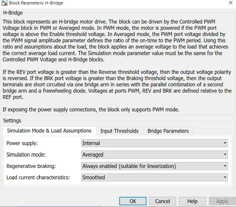
This block is used as a converter block in which input DC source from battery is converted to controlled DC voltage accouding to the PWM signal voltage.
We have to select the DC as intrenal/external.For internal voltage the DC source voltage is assigned as load rated voltage.In external power supply we can manually assign the battery voltage.Simulation mode should be selected as PWM or Averaged. Regenerative braking shoul be enabled always and load current character as smoothed for ripple free output current supply.
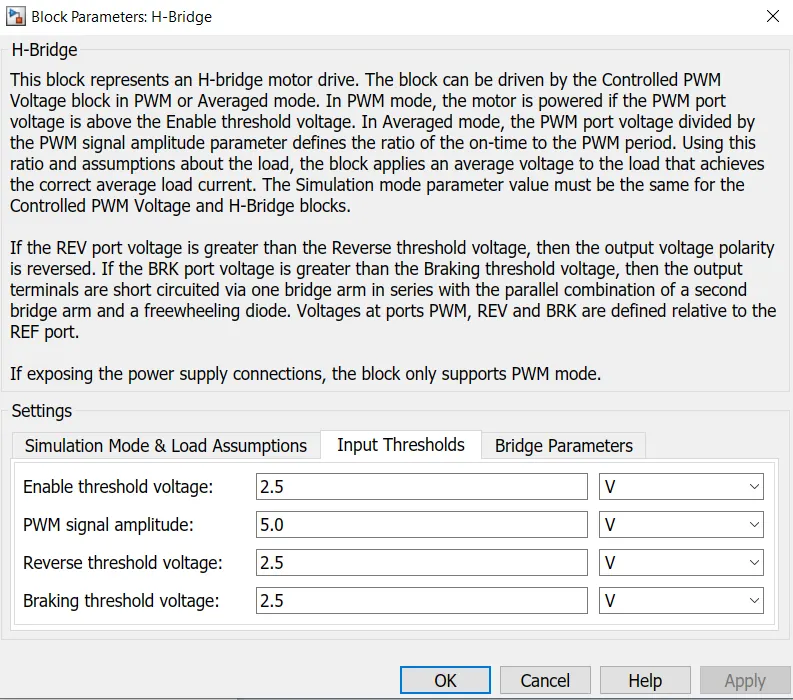
In input thresholds, we have to set the ON condition of switchs threshold voltage,PWM singal amplitude as in Controlled PWM output voltage,reverse threshold voltage(not used in our model),braking threshold voltage.
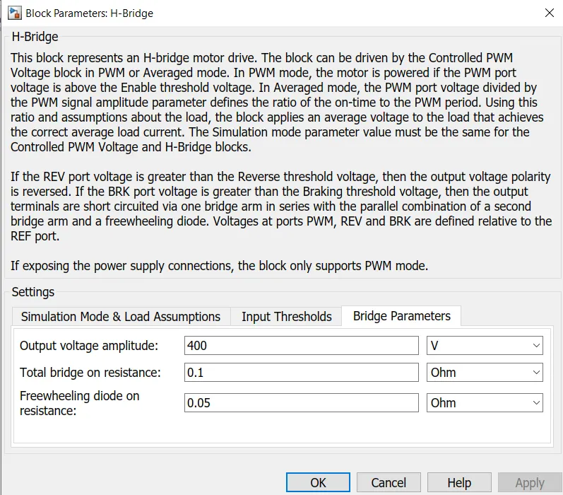
In bridge parameters,we have to give output voltage value from bridge to motor,bridge resistance and free wheel diode resistance as on ON condition.
For our model we configured the parameters and its values as shown below.
(d)DC Motor(Brush type):
This is simple DC brush type motor.This block consist of both electrical and mechanical parts as we have to configure based on our load parameters.
In electrical torque tab, we can choose the motor type as wound rotor/permanent magnet. Model parameterization as given by,
- Rated load and speed .
- By equivalent circuit parameters.
- By stall torque and no-load speed.
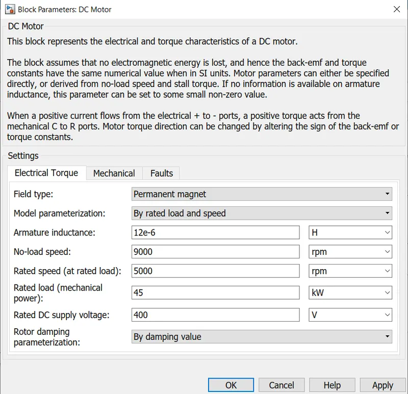
The values for no load speed,rated speed,armature inductance,rated load(mechanical power),rated DC supply voltage are assigned in this block parameters.Rotor damping parameteraized as no load current or by rotor damping value given in mechanical tab.
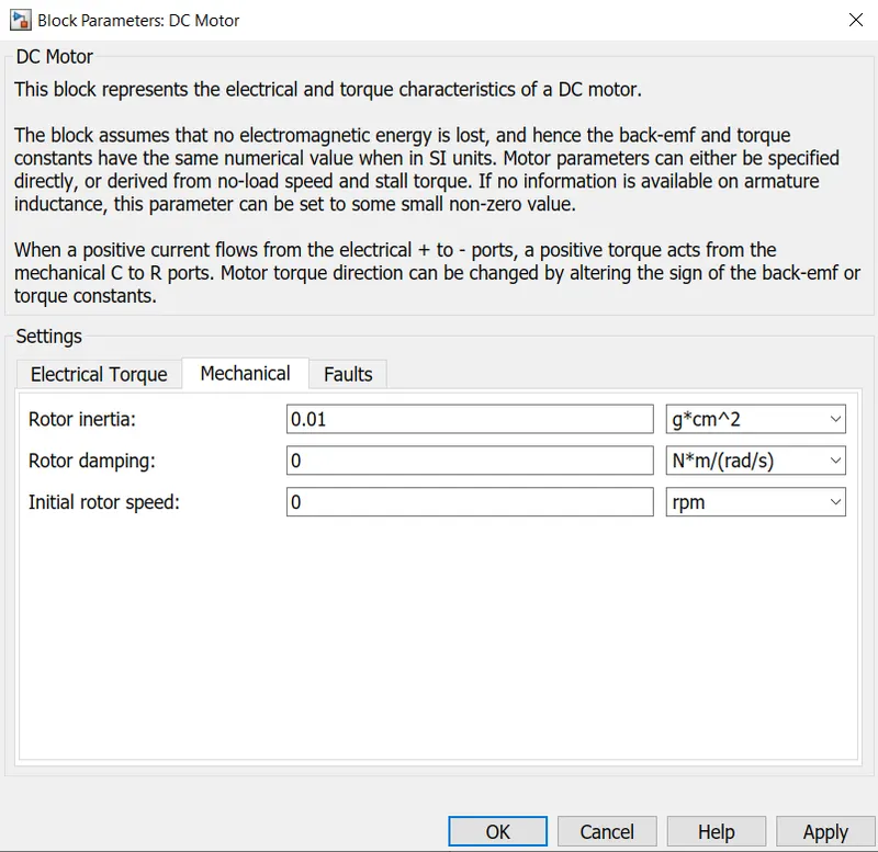
In mechanical tab rotor inertia,rotor damping ,initial rotor speed values should be given.
For our model we are configured the motor electrical and mechanical values as shown below.
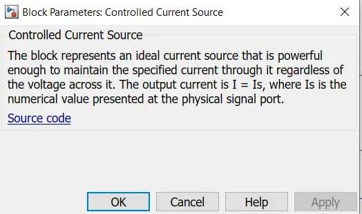
(e)Controlled current source:
This block will produce variable current flow according to the current signal values from current sensor or any other current pulse signals.
For our model the current sensor values are give as input to this block for charging and discharging the battery.
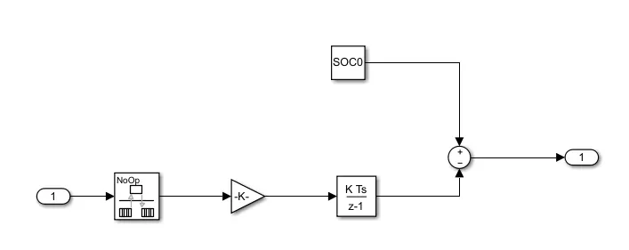
(f)SOC unit:
This unit is used to monitor the charging and discharging of battery.
The input current values are given to a seperate battery externally by using controlled current source.The current values from sensor given to a rate transition block to convert current values to per unit rated value. That is multiplied by gain(1/AH*3600) to find charge consumed at one second.After that a discrete time integrator converte energy to percentage form,compared with SOC value 100 gives the remaining result in percentage for every current value of every second from current sensor.
(g) Current sensor:
This block measure the current flow at every second.
(h)Voltage sensor:
This block is used to sence the voltage between two terminals for every second.
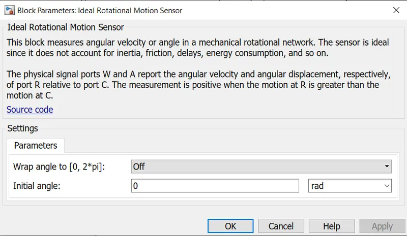
(i)Ideal rotational motion sensor:
This block will measure the speed of rotational mechanical input in rad/s.
(4)Vehicle body:
(a)Tire:
This block represents the tire of the vehicle body customised by magic formula where B,C,D,E coefficient values should be given.
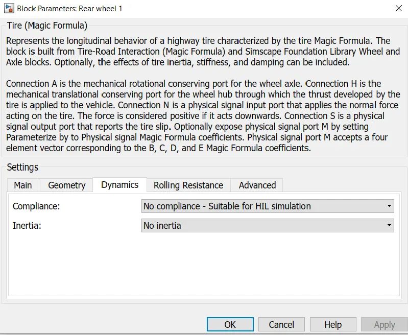
In geometry tab wheel radius should be given.In dynamics tab stiffness,damping,inertia,initial velocity values are given if required.
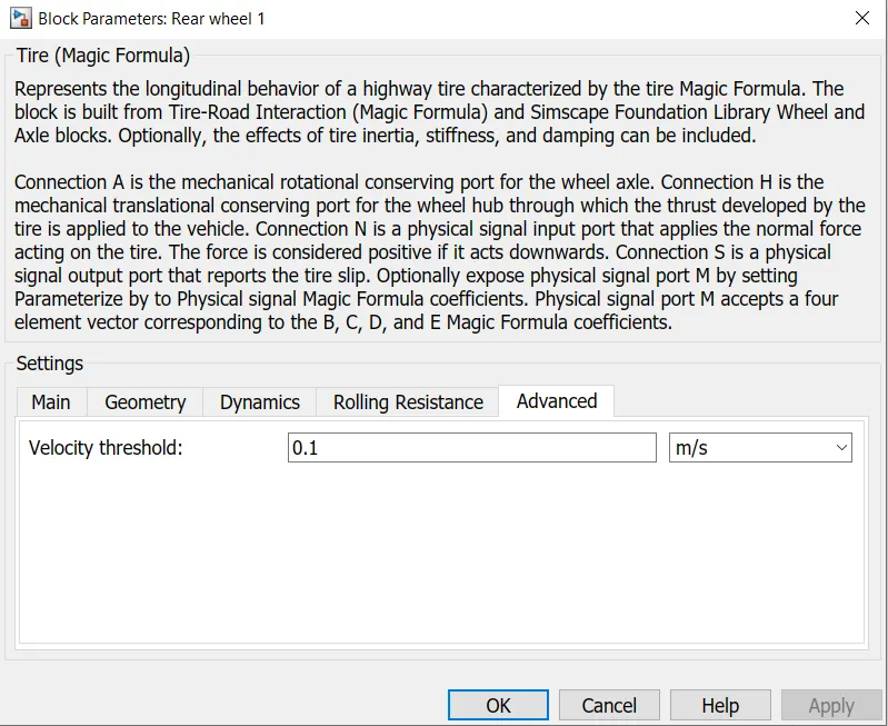
Rolling resistance value should be given if required.In advance tab velocity thershold value is given.
For our model we are having the default vales as shown below.In dynamics tab, no compliance and no inertia is given by default.

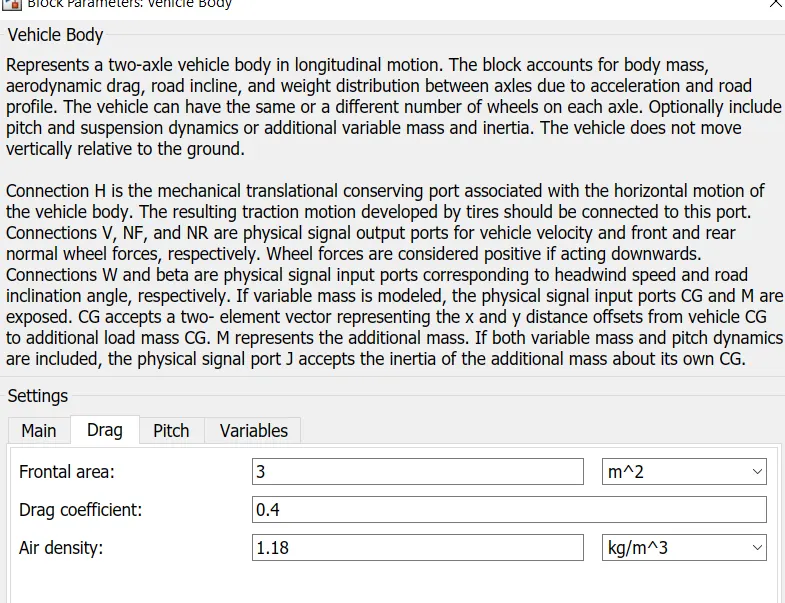
(b)Vehicle body:
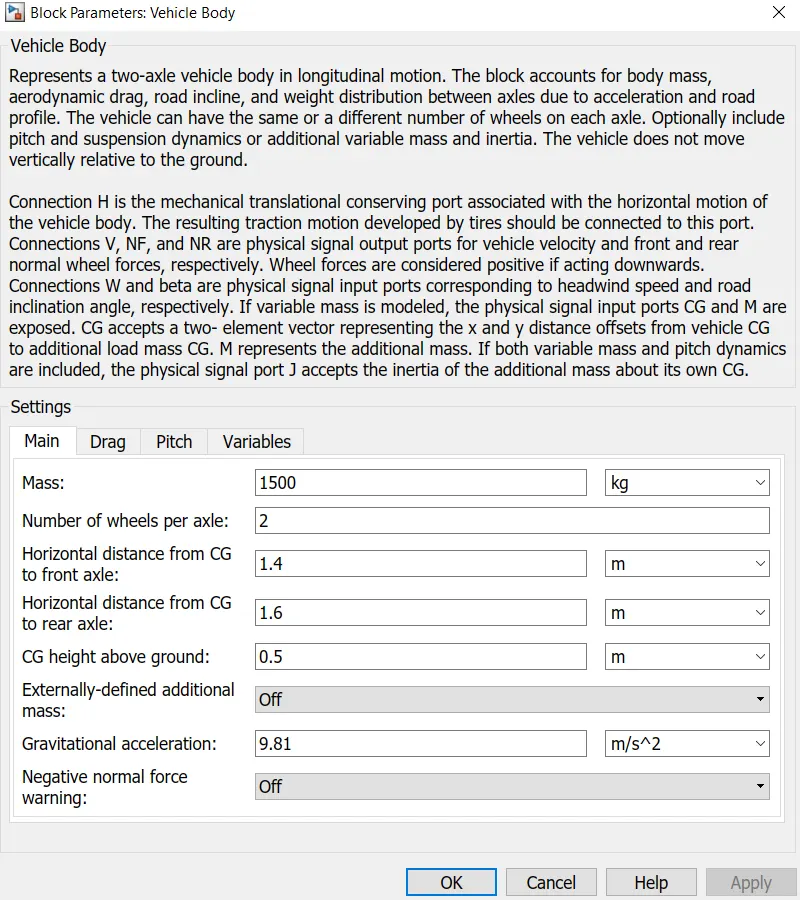
This is two axle longitudinal motion vehicle body.
Here mass of vehicle,no.of wheels per axle,horizontal distance of front and rear axle from CG,CG height above ground, acceleration due to gravity are assigned in main tab.
Vehicle drag values,pitch value if required are given .
For our model, our vehicle parameter values are shown below.
(c)Simple gear:
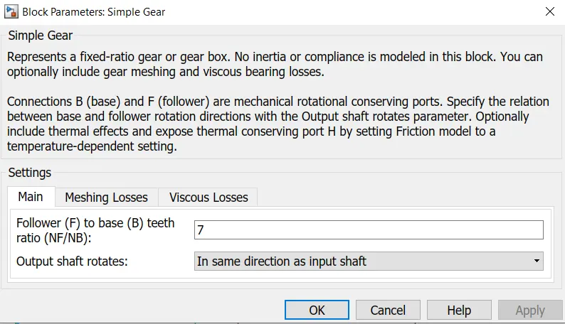
This block couples motor shaft with vehicle axle with gear ratio.
The motor shaft side as base and axle side as follower.
For our model we had given gear ratio as 7:1.We have assumed as no meshing loss and 0 viscous losses.
Working of model:
- Initially the velocity data with respect to time from drive cycle FTP75 given as referance to longitudinal drive "velref" input.
- The driver feedback velocity input is given as speed from vehicle body output. It compare both the velocities,give output pulses as acceleration and deceleration commands.
- In our model let as assume no slope is present on ground surface, vehicle moves in flat surface as grade given as 0. The main condition in this block is the drive sycle referance speed and feedback speed should be in same unit for comparing using PI controller.
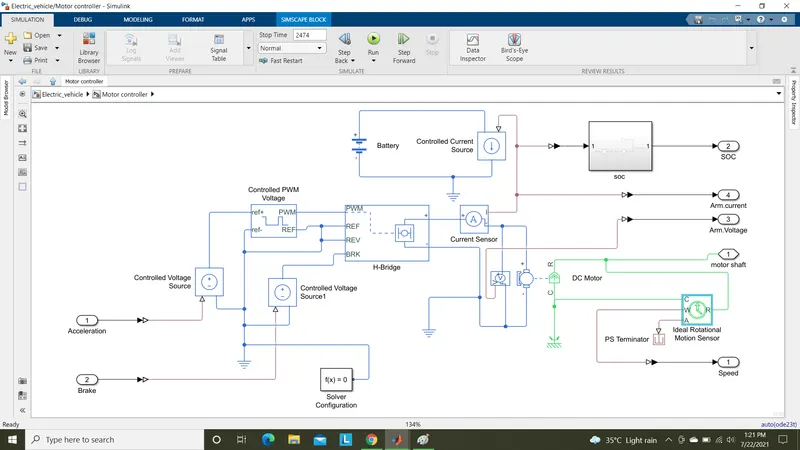
- The acceleration and deceleration commands are in simulink signals.So we have to convert to physical signals using Simulink-PS converters.
- The converted physical signals are given as input variable signals to controlled voltage sources for inputs to controlled PWM signal block and break input to H-bridge.
- The acceleration Voltage source values are given to controlled voltaage source and given to PWM port of H-bridge.
- The deceleration voltage source is directly conected to break port of H-bridge.
- All referance ports are grounded with electrical referance.Here in the drive cycle we are not reversing the vehicle,so rev port also connected to electrical referance.
- In H-bridge circuit the input power supply source from battery is given as internal power supply mode,as voltage assigned as rated voltage output of H-bridge.The output of H-bridge connected to a DC brush type motor terminals through current sensor block for measuring armature current of motor. A voitage sensor is connected across two terminals of motor for measuring armature voltage of motor.
- Here the motor is rated as 400V and rated load capacity as 45KW. No-load rpm as 9000rpm and rated rpm at rated load as 5000rpm.The motortype is selected as permanent magnet.
- The mechanical output through the shaft is coupled with the axle of vehicle body through a simple gear.A ideal rotational motion sensor is connectes across R and C ports of Shaft to find the angular speed of motor shaft.
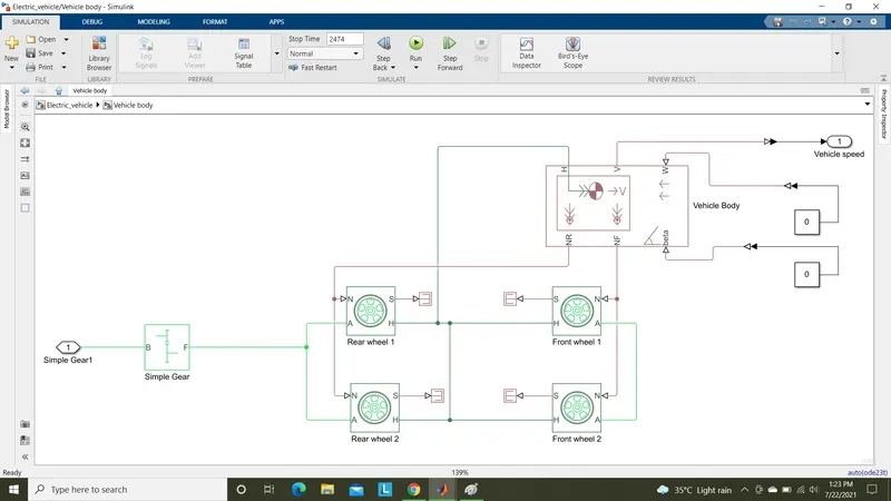
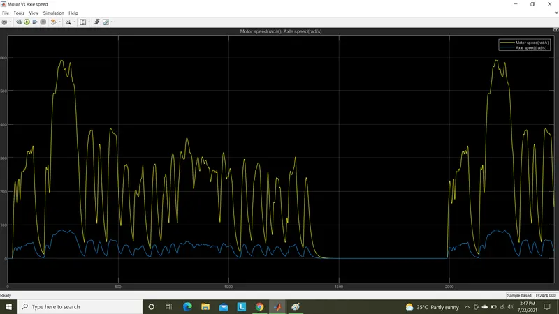
- In vehicle body, the simple gear ratio is given as 7 for our model.Which means & times the base speed equals the follower speed.Here base speed as motor shaft speed and follower speed as Axle speed.
- Tire parameters are configured for front and rear wheels.The forces for both front and rear wheels are connected through NR,NF ports.All H ports of wheels are connected to hub of vehicle body.
- All S (slip) ports of wheels are connected to ps-terminator blocks as no slips are considered in our model.The grade angle and wind drag values are given through W,beta ports.
- The output velocity of vehicle can be viewed by V port.
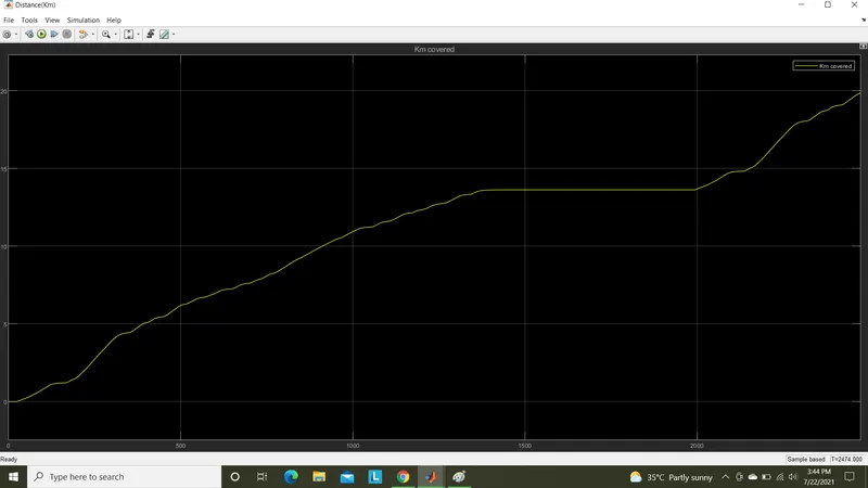
- For finding the distance travelled by the vehicle the speed value multiplied by 3.6 for Kmph and then integrated.The integrated values are divided by 3600 for converting to distance travelled in per second.
- The vehicle velocity output given as feedback to longitudinal driver for comparison with referance drive cycle speed.
- For every second the vehicle velocity is compared with referance drive cycle velocity, based on that vehicle speed is controlled.
Results:
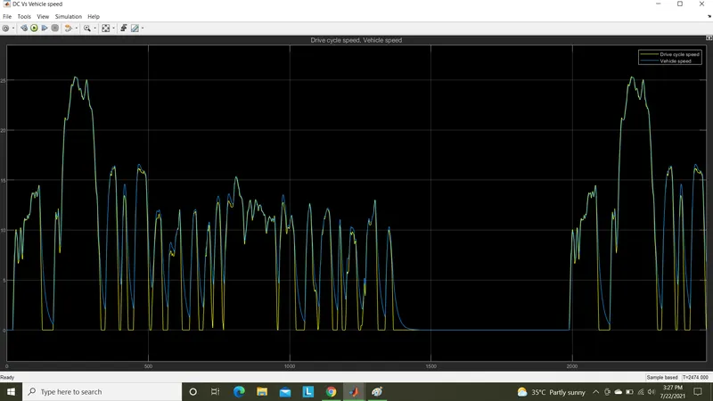
The vehicle velocity controlled to referance drive cycle volocities as shown below scope result.
The distance covered by vehicle is 19.84 Kms from display & scope.
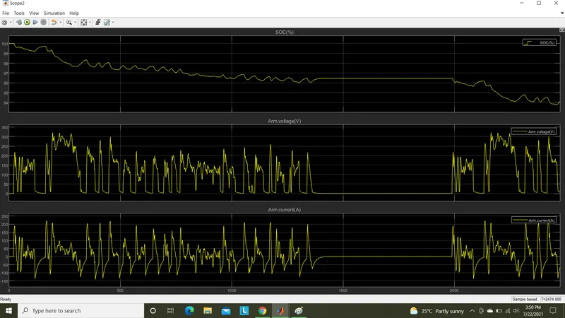
The Soc,armature voltage and currents are shown below,
The motor speed & axle speed in rad/s varies by 7:1 ratio is shown below,
Conclusion:
From the above results we justified that,
- The vehicle velocities is controlled with drive cycle velocities.
- The Soc of battery charged during deceleration periods and discharges during acceleration period.
- For this drive cycle the the charge reduced to 94% from 100% for the distance covered of 19.84 Kms.
- The motor shaft rpm is 7 times of axle side rpm.
- The armature current are in +positive direction when accelerating and in -negative direction during deceleration as it charging the battery.
- The armature voltages varies accordingly to switching pulses from H-bridge.
- We can also change the motor ratings accordingly with gear ratios to increase the vehicle ranges.
All result images and model file are attached in google drive link and outside.
Drive link:https://drive.google.com/drive/folders/15EsbzeGQ8qcIjqpFgE6AoJBQWpZnsoW-?usp=sharing
Thank you
Submitted by,
Praveen Kumar L V,
Date:22/07/2021.