Vehicle Dynamics - Roll Bar Selection & Understeer Budget
AIM: To select roll bar and prepare an understeer budget sheet for a light weight sporty vehicle.
OBJECTIVES:
1. Select roll bar diameters to meet target roll gradient
2. Select kinematic and compliance parameters to meet target understeer gradient
GIVEN DATA:
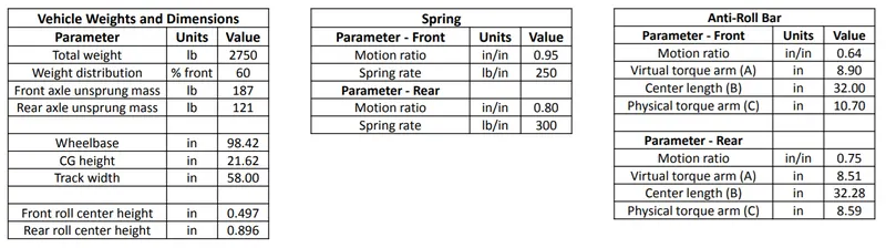
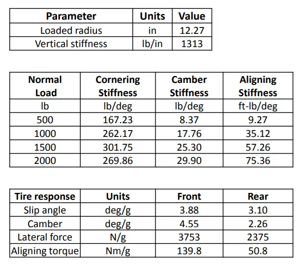
TARGETS & CONSTRAINTS:
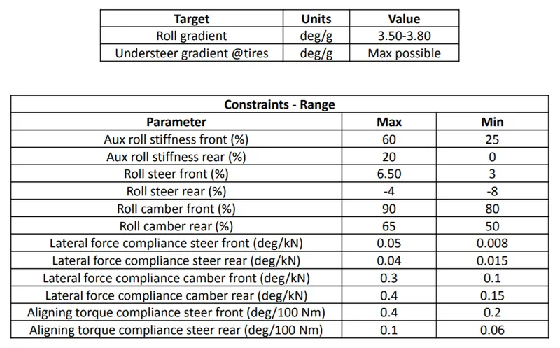
SOLUTION:
1. Roll Bar Calculations:
i) The CG distance from front and rear is calculated using the weight distribution.
Front axle to CG distance,
`a = (m_(s_r)* WB)/m`
Rear axle to CG distance,
`b = (m_(s_f)*WB)/m`
where,
`WB ->` wheelbase (in)
`m ->` Total sprung mass (lbs)
`m_(s_f) ->` Front sprung mass (lbs)
`m_(s_r) ->` Rear sprung mass (lbs)
ii) Sprung mass roll moment arm length,
`h_(arm) = h - (Z_(RC_f)*b + Z_(RCr)*a)/(WB)`
where,
`h ->` CG height (in)
`Z_(RC_f) ->` Front Roll Centre height (in)
`Z_(RC_r) ->` Rear Roll Centre height (in)
iii) The lateral load transfer is calculated using the following procedure-
Total load transfer,
`LT_(lat) = (W*h)/T`
where,
`W ->` Total weight (lbs)
`T ->` Trackwidth (in)
Load transfer at front is needed to be 5% more for achieving understeer.
`LT_f = LT_(lat)*(%W_f + 5)/100`
Front load transfer due to unsprung mass,
`LT_u = (m_(u_f)*r_t)/T`
where,
`m_(u_f) ->` Front unsprung mass (lbs)
`r_t ->` tire radius (in)
Front load transfer due to forces on sprung mass,
`LT_s = (m_(s_f)*Z_(RC_f))/T`
where,
`m_(s_f) ->` Front sprung mass (lbs)
Front load transfer due to roll,
`LT_(phi) = LT_f - LT_s -LT_u`
iv) The roll moment has two components, lateral component and gravity component.
Lateral component,
`M_(phil) = m_s*h_(arm)`
where,
`m_s ->` Total sprung mass (lbs)
Gravity component,
`M_(phig) = m_s*h_(arm)*(phi)/A_y *pi/180`
where,
`phi/A_y ->` Roll gradient (deg/g)
Total roll moment,
`M_(phi) = M_(phil) + M_(phig)`
v) Roll stiffness
Total roll stiffness due to roll gradient,
`k_phi = M_phi/phi`
Front roll stiffness at tire,
`k_(phif) = (LT_phi*T)/phi`
Rear roll stiffness at tire,
`k_(phir) = k_phi - k_(phif)`
Roll stiffness due to wheel rate contribution,
`k_(phiw) = k_w* (TW^2)/2`
Roll stiffness due to tire rate contribution,
`k_(phit) = k_t*(TW^2)/2`
Roll stiffness at wheel centre (removing tire effect),
`k_(phiWC) = (k_(phit)*k_phi)/(k_(phit) - k_phi)`
Auxiliary roll stiffness,
`k_(arb) = k_(phiWC) - k_(phiw)`
% auxiliary roll stiffness,
`%k_(arb) = (k_(arb)*100)/k_phi`
vi) Anti-roll stiffness calculations-
Anti-roll stiffness `=(500000*D_o^4)/(0.4422*A^2B+ 0.2264*C^3)`
Anti-roll stiffness for one wheel jounce `=(500000*(D_o^4 - D_i^4))/(0.4422*A^2B+ 0.2264*C^3)*MR^2*(TW^2)/2`
where,
`D_o, D_i ->` Outer and Inner diameter of anti-roll bar respectively
`A ->` Virtual torque arm length
`B ->` Centre length
`C ->` Physical torque arm length
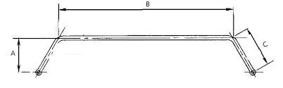
vii) We need a solid anti-roll bar, hence we set the inner diameter to zero. The outer diameter value was altered till we get a good anti-roll stiffness.
2. Understeer Gradient Calculations:
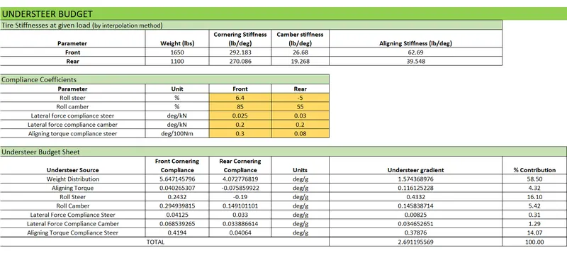
The total understeer gradient of a vehicle is the sum of number of effects as given below-
i. Weight Distribution:
`K_(weight) = W_f/C_(alpha_f)-W_r/C_(alpha_r)`
ii. Aligning Torque:
`K_(at) = W_f/(2*C_(alpha_f))*p_r/b+W_r/(2*C_(alpha_r))*p_f/a`
where,
`p_f, p_r =>` Front and Rear pneumatic trail respectively
iii. Roll Steer:
`K_(rollsteer) = (epsilon_f-epsilon_r)(dphi)/(da_y)`
where,
`epsilon_f, epsilon_r =>` Front and Rear Roll Steer coefficient
`(dphi)/(da_y) =>` Roll gradient
iv. Roll Camber:
`(C_(gamma_f)/C_(alpha_f)*(delgamma_f)/(delphi) - C_(gamma_r)/C_(alpha_r)*(delgamma_r)/(delphi))(delphi)/(dela_y)`
where,
`C_gamma =>` Camber stiffness
`(delgamma)/(delphi) =>` Roll Camber Coefficient
v. Lateral Force Compliance Steer:
`K_(lfcs) = A_fW_f-A_rW_r`
where,
`A_f, A_r =>` Lateral Force Compliance Steer Coefficient
vi. Lateral Force Compliance Camber:
`LFCgamma_f*C_(gamma_f)/C_(alpha_f)*F_(y_f) - LFCgamma_r*C_(gamma_r)/C_(alpha_r)*F_(y_r)`
where,
`LFCgamma =>` Lateral Force Compliance Camber Coefficient
`F_y =>` Lateral Force
vii. Aligning Torque Compliance Steer:
`ATCS_f*AT_f - ATCS_r*AT_r`
where,
`ATCS =>` Aligning Torque Compliance Steer Coefficient
`AT =>` Aligning Torque
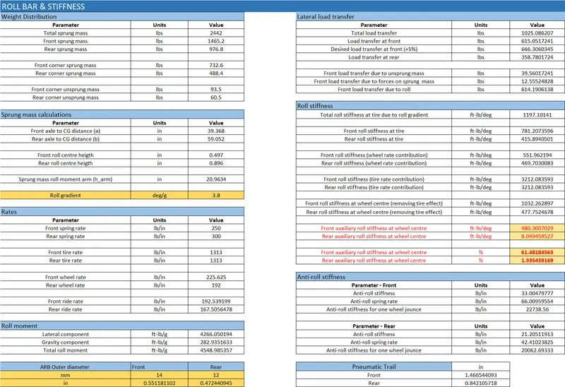
The calculations were done in an excel sheet.
Excel Sheet (snapshots):
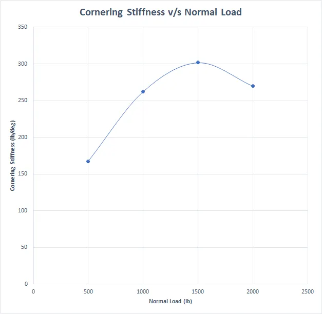
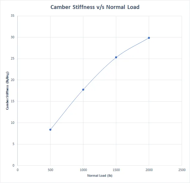
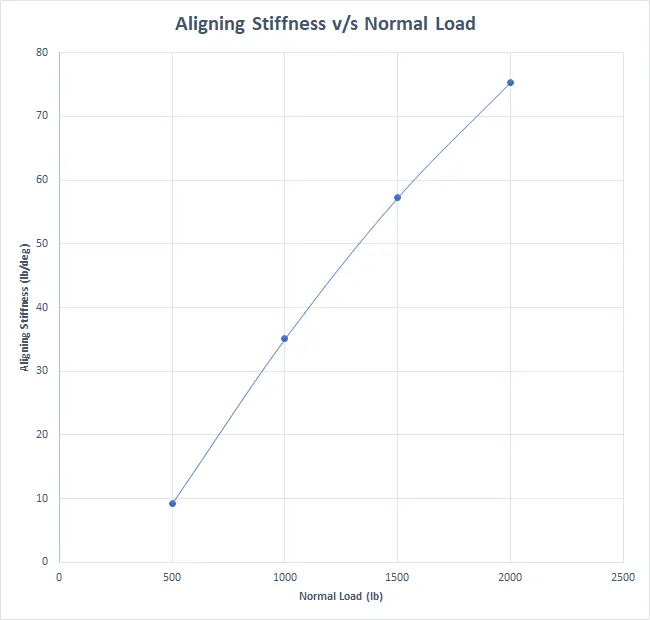
Tire Stiffness Plots:
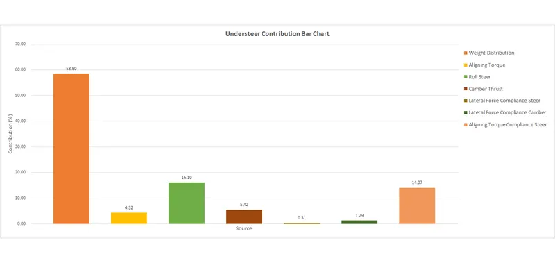
Understeer Bar Chart:
The excel sheet can be found in the following Google Drive link:
(https://drive.google.com/file/d/1HBtMphZOjaTcK6ozsbjLdxxyW6Z9BvXn/view?usp=sharing)
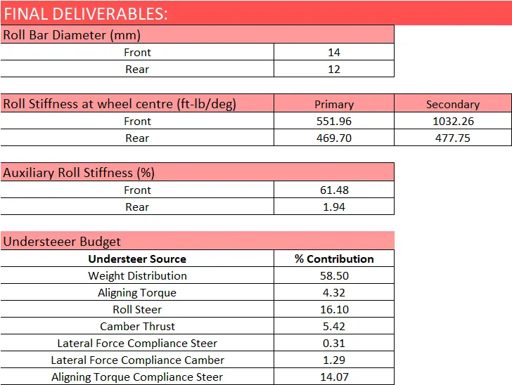
FINAL DELIVERABLES:
| Roll Bar Diameter (mm) | ||
| Front | 14 | |
| Rear | 12 | |
| Roll Stiffness at wheel centre (ft-lb/deg) | Primary | Secondary |
| Front | 551.96 | 1032.26 |
| Rear | 469.70 | 477.75 |
| Auxiliary Roll Stiffness (%) | ||
| Front | 61.48 | |
| Rear | 1.94 | |
| Understeeer Budget | ||
| Understeer Source | % Contribution | |
| Weight Distribution | 58.50 | |
| Aligning Torque | 4.32 | |
| Roll Steer | 16.10 | |
| Camber Thrust | 5.42 | |
| Lateral Force Compliance Steer | 0.31 | |
| Lateral Force Compliance Camber | 1.29 | |
| Aligning Torque Compliance Steer | 14.07 |
CONCLUSION: The roll bar diameter was determined and the understeer budget sheet was generated. All the parameters calculated are well and good withing the limits.