FINAL INDEPENDENT PROJECT
Phase 1
- Pick up a physical system or setup which you want to analyze using simulation tools, design software or computer programs - Stapler
- Explain what you plan on calculating through this simulation/program/design - to design a Stapler in solidwoks from scratch. research for geometry and dimensions. generate parts and assemble in Solidworks assembly. Render the parts and assembly using PhotoView 360.
- Explain the engineering significance of your project - A stapler is an under-rated product. it is a fine piece of mechanical engineering which is often taken for granted. the product comes handy in plenty of situations. it is a wonder how such small useful piece actually is an assembly of 7 different parts.
Independent project Solidworks
Title of the Project
Stapler design in Solidworks
Objective
to design a Stapler in solidwoks from scratch. research for geometry and dimensions. generate parts and assemble in Solidworks assembly. Render the parts and assembly using PhotoView 360.
Introduction
Solidworks is used by many small scale businesses due to its affordability and the ease of design and the simple User Interface it offers. Rendering capability is a cherry on top of cake.
in this project, a stapler is designed from scratch. dimensions of parts are referred from online. the parts made are put into an assembly for a wholesome view and idea of how the product functions.
to see how it looks in the real world, PhotoView 360 is used to render the parts and assembly.
Motivation for Project
A stapler is an under-rated product. it is a fine piece of mechanical engineering which is often taken for granted. the product comes handy in plenty of situations. it is a wonder how such small useful piece actually is an assembly of 7 different parts.
Name of Parts
stapler base mounts the pin, stapler top and stapler holder. stapler pusher is insrted into the stapler holder. extruder is mounted on stapler top. plastic part is attached to the stapler base and top.
Explanation for Assembly
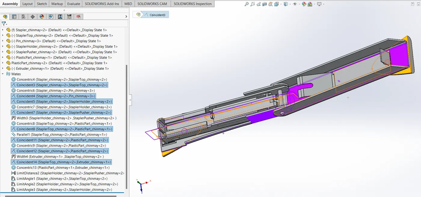
the stapler base is the first part imported. it is set to fixed by default by the software.
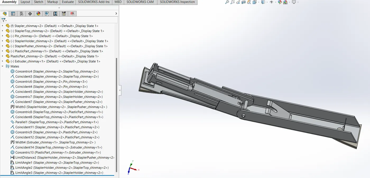
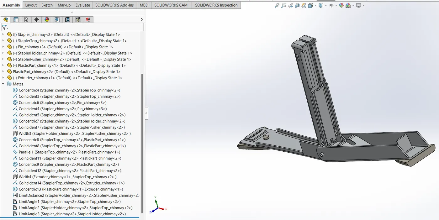
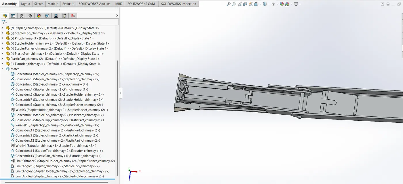
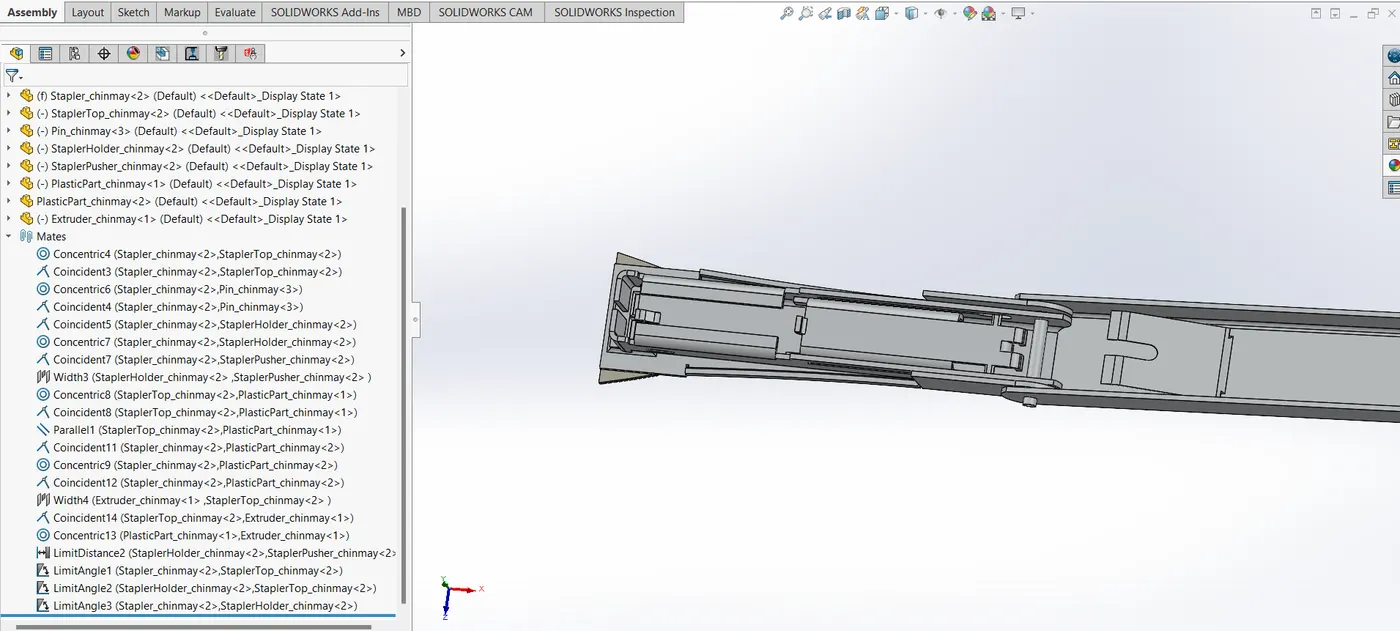
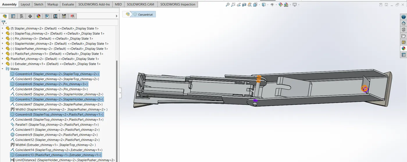
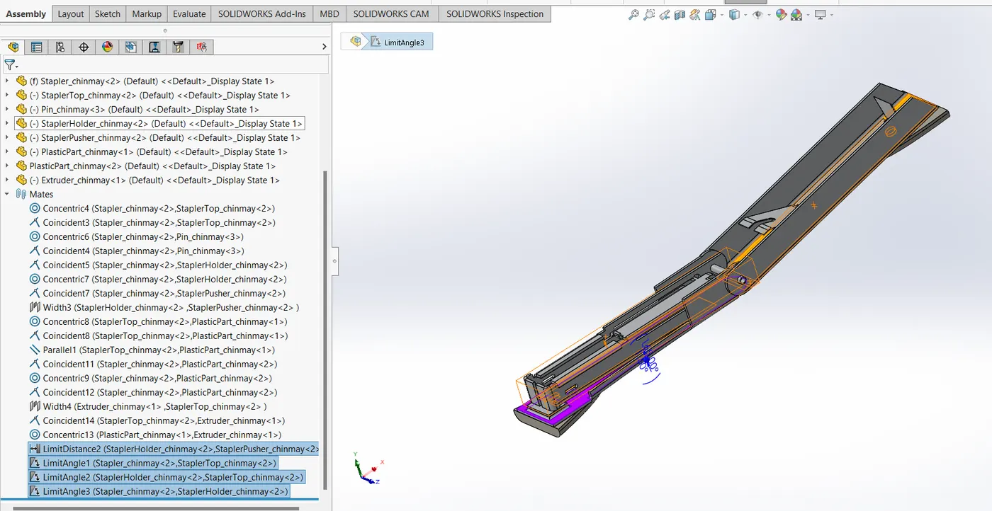
then stapler top is imported. is made concentric mate with base. angle limitation is applied on the two faces as shown in the assembly and images. the maximum travel is constrined to 170 degrees
and the minimum travel to 0 degrees. its mid plane is made coincident with that ofthe stapler base.
then the pin is imported and is applied a concentric mate. this facilitated the angular motion between the earlier two imported parts. the mid plane of pin is made coincident with that ofthe stapler base.
the next part imported is the stapler holder. it is again concentric mated and coincident mid plane mated with the stapler base. an angular mate is applied to this and the stapler base, a minimum of
1.5 and maximum of 165 degrees. it is also angle mated with the stapler top with minimum angle of 5 degrees and the maximum angle of 167 degrees.
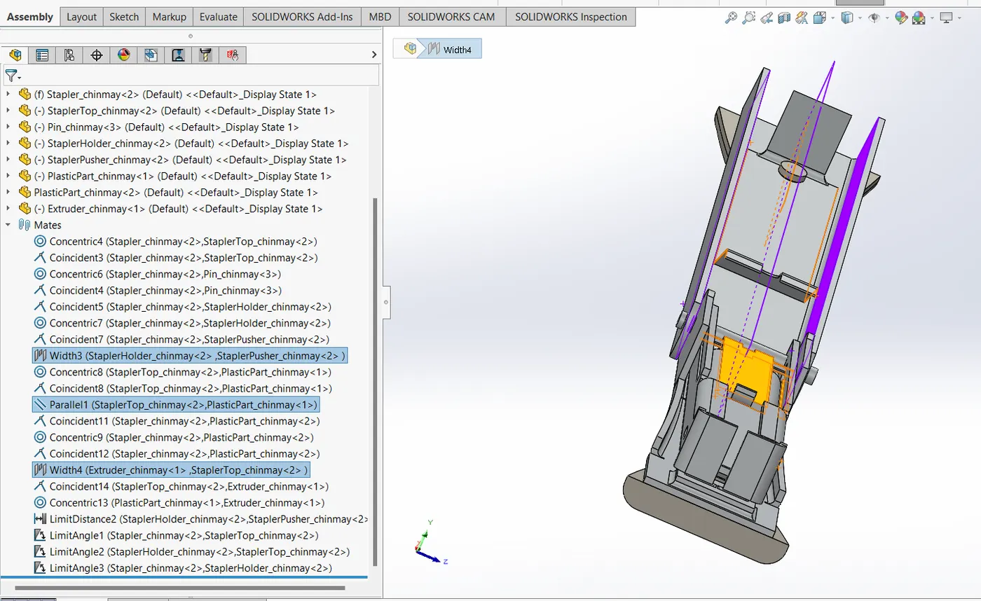
the next part imported is teh stapler pusher. it is made a width mate with the holder, so as to lie within the boundary contrains all the time. it is also applied a limit distance mate with stapler holder
front of a minimum distance of 0 mm and a maximum of 30 mm.
the lat pasrt imported is the extruder. is is coincident mated to the surface of stapler top. then concentric mated with the hole in which the plastic part goes into. then its mid plane is made coincident
with that ofthe stapler top.
these are all the assembly contrains which go into the assembly of stapler. when we set the stapler base to float, all the parts float together as an assembly. this implies the successful constrains
given in the assembly.
Explanation for Rendering
stapler can be genereally used in many applications. some of them could be in the kitchen or making handy projects, parts of which could be scattered all accross the floor. so renders are done one pertaining
to the kitchen and the other to the floor. images are attached.
Design methodology / approach
Overall flowchart -
(1)sketch - (2)part - (3)assembly - (4)render
(1)Sketch -
use line, circle, arc, spline, slot, trim entities, convert entities, offset entities, mirror entities, linear sketch pattern, blocks , dimension etc. to make a fully defined skectch.
(2)Part -
use features on the drawn sketches, to make a part. use features like extruded boss, revolved boss, swept boss, extruded cut, revolved cut, swept cut, fillet, pattern, mirror, reference geometry, curves, split etc. to make parts.
(3)Assembly -
import parts one by one in an assembly file and add constraints over them to align them into an assembly. use mates like coincident, tangent, distance, limit angle, width, parallel, angle, concentric etc. to align and fix parts. mirror them if necessary.
(4) render -
we use solidworks add-in Photo View 360 to render the image. when we want to see how the CAD model looks in real life with all the nuances of light playing on its surface, we go to render a model.
there are numerous setting options in rendering. you can add decals, which can be seen in the models attached with this report as well. appearances can be edited. so can the scene in which the CAD model is to be placed.
we see integrated previews to have a wuick look on how the model behaves in conditions to lighting adn overall look. preview windows does a similar job. final render shows us how the image is going to be after wverthing is kept in check.
when we want to select a specific region to render, we use render region option. ther are a lot of choices offered by SOlidworks to select the lighting conditions, camera positions, adding decals on thg decals on the parts etc.
there is an Options setting where we choose output image size, render quality - good, best, maximum; bool options, contour/cartoon rendering, direct caustics, network rendering and more.
if the render is expected to take a lot of time, we can schedule it. also recalling last render is one of useful options to play with.
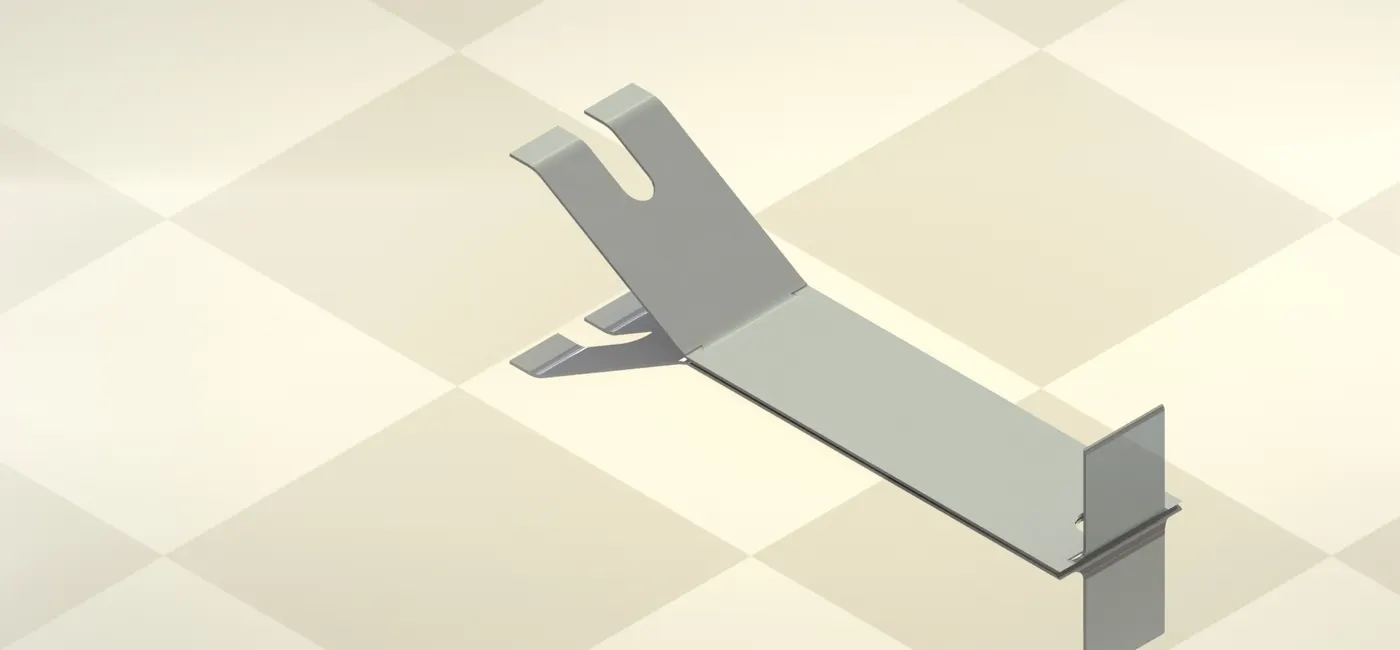
Description (Need to explain tools/ Features used while designing) along with the images of Part files
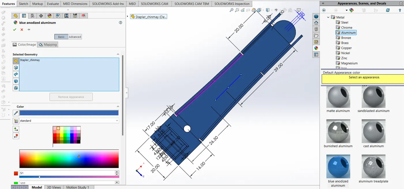
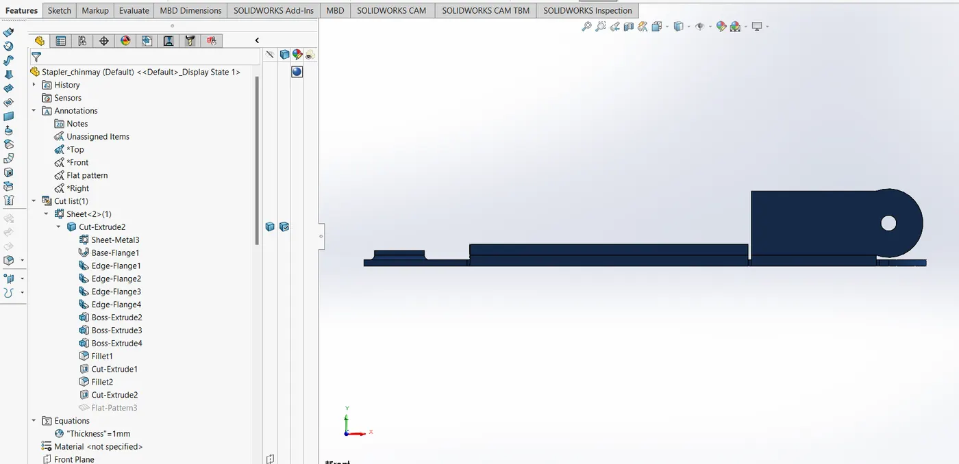
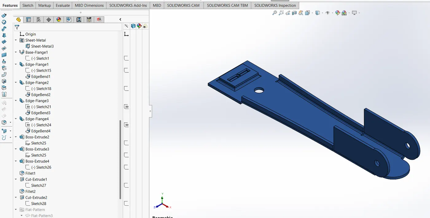
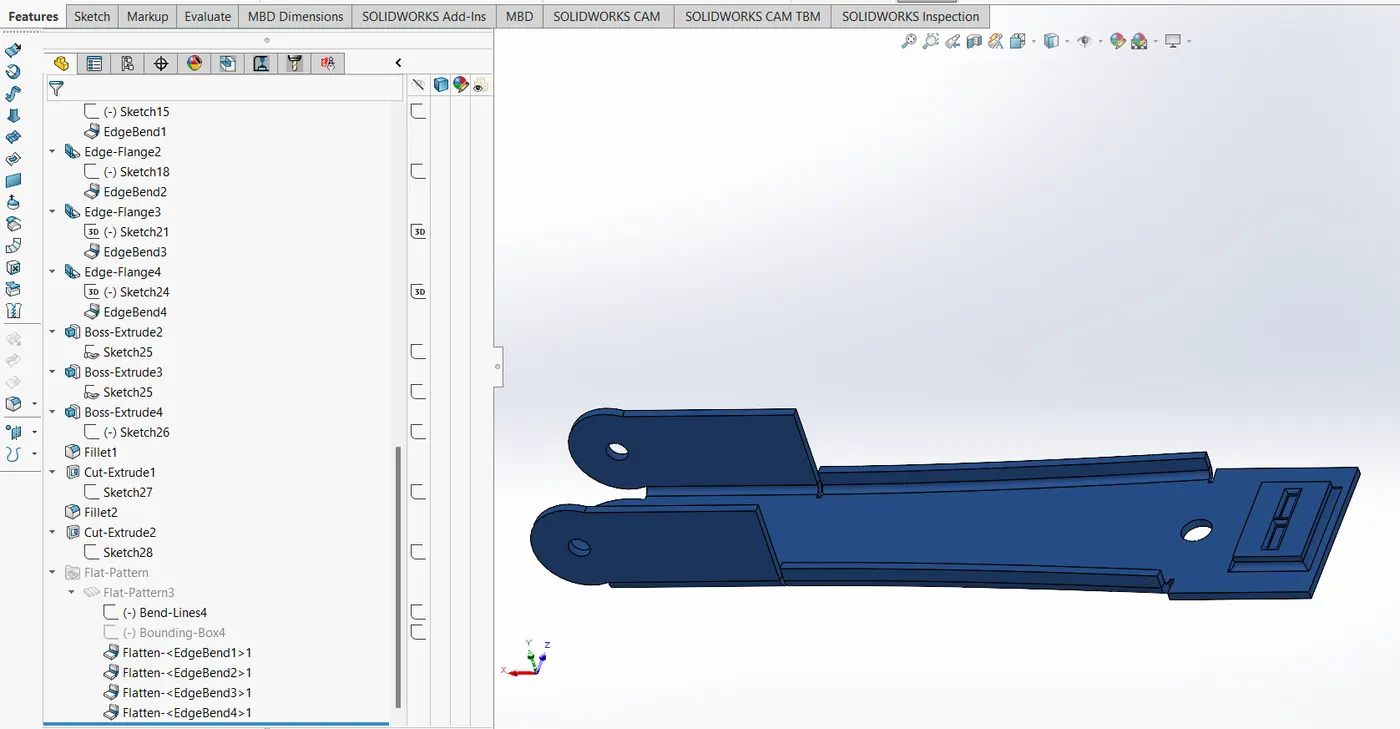
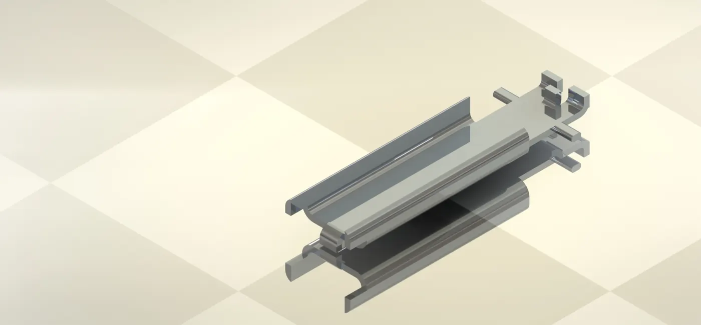
Stapler base (aluminium):
features used- sheet metal feaures are mainly used here - base flange, edge flange, boss-extrude, fillet, cut-extrude
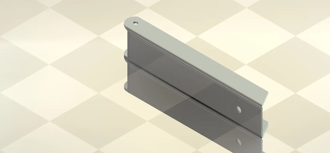
Stapler top (aluminium):
features used- sheet metal feaures are mainly used here - base flange, sketched-bend, cut-extrude
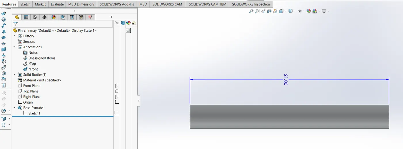
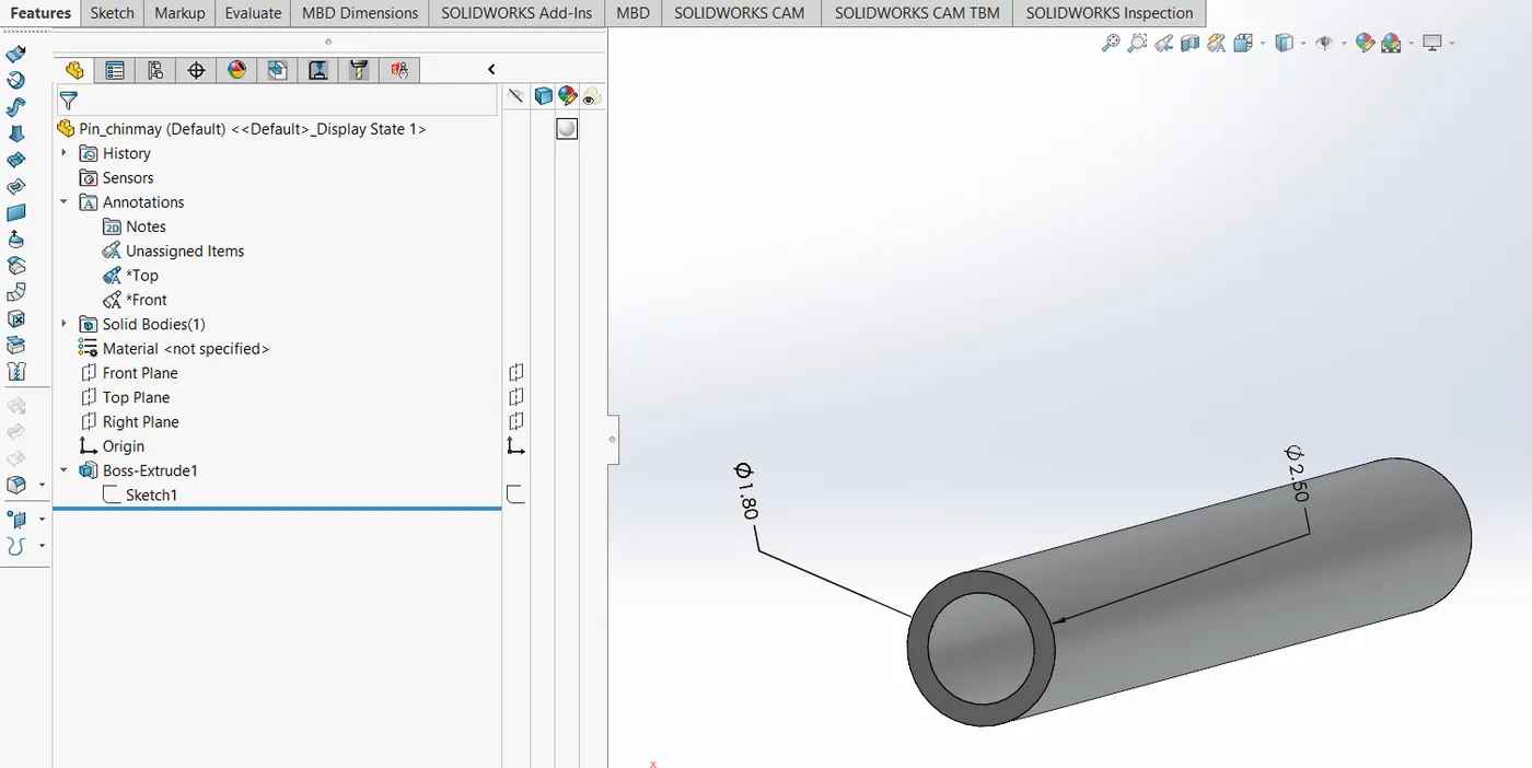
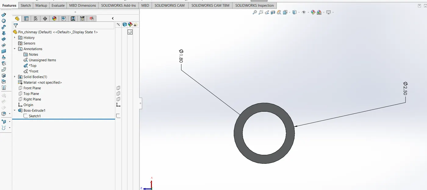
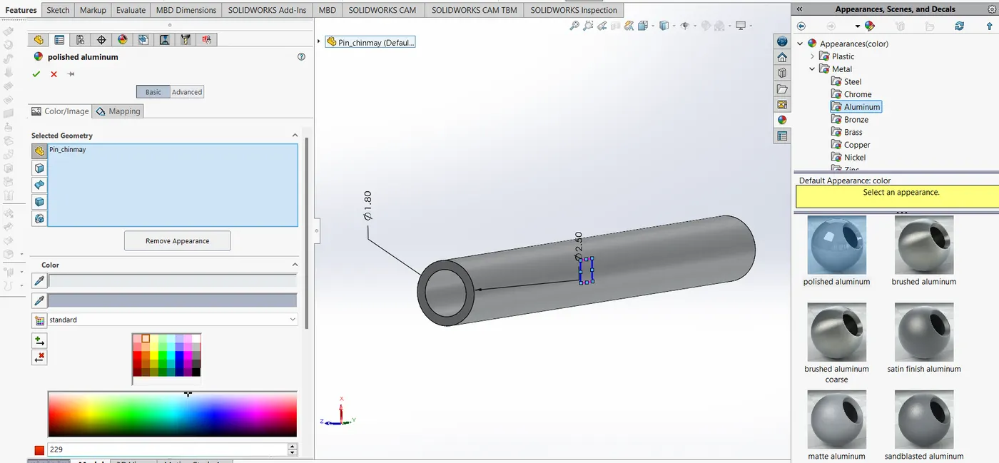
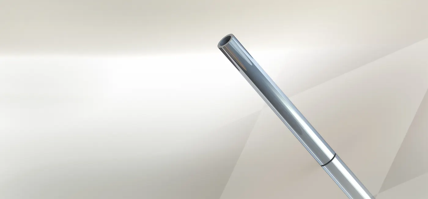
Pin (aluminium):
features used- sheet metal feaures are mainly used here - boss-extrude
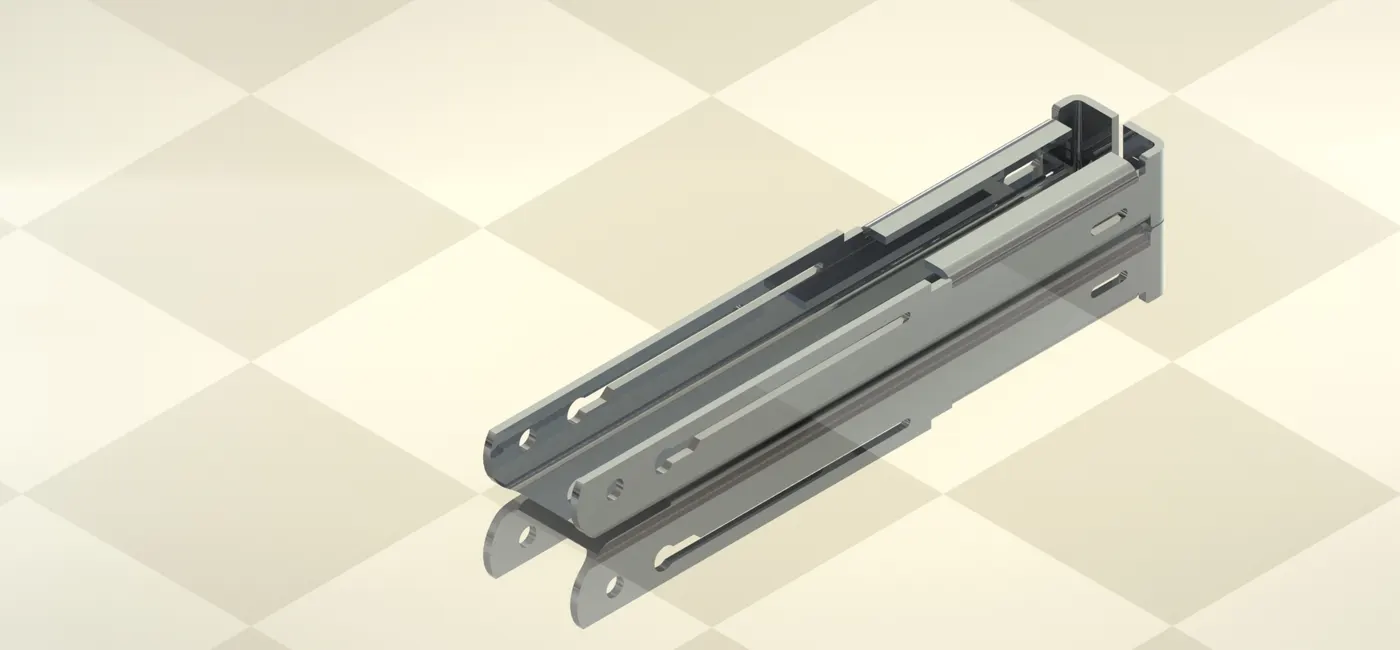
Stapler holder (aluminium):
features used- sheet metal feaures are mainly used here - base flange, edge flange, boss-extrude, fillet, cut-extrude
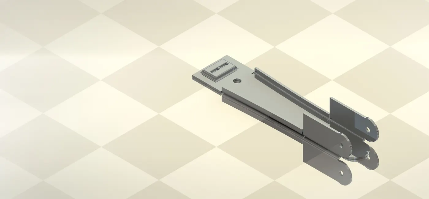
Stapler pusher (aluminium):
features used- sheet metal feaures are mainly used here - base flange, edge flange, boss-extrude, fillet, cut-extrude
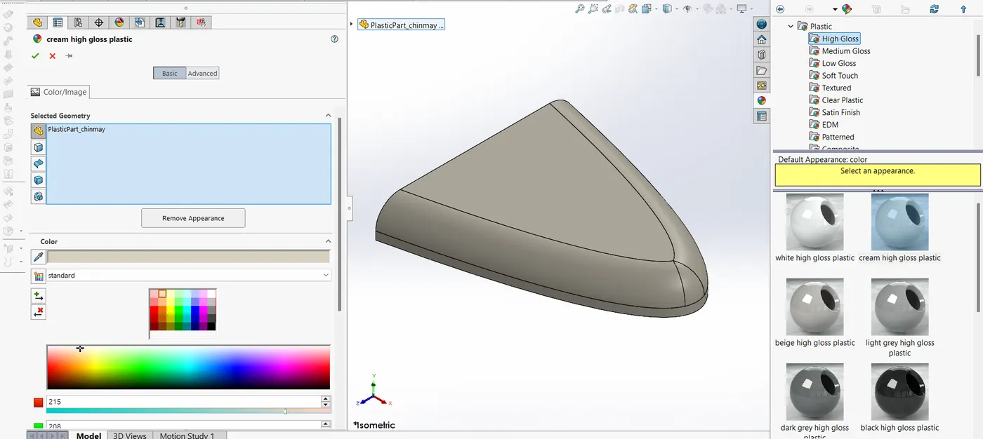
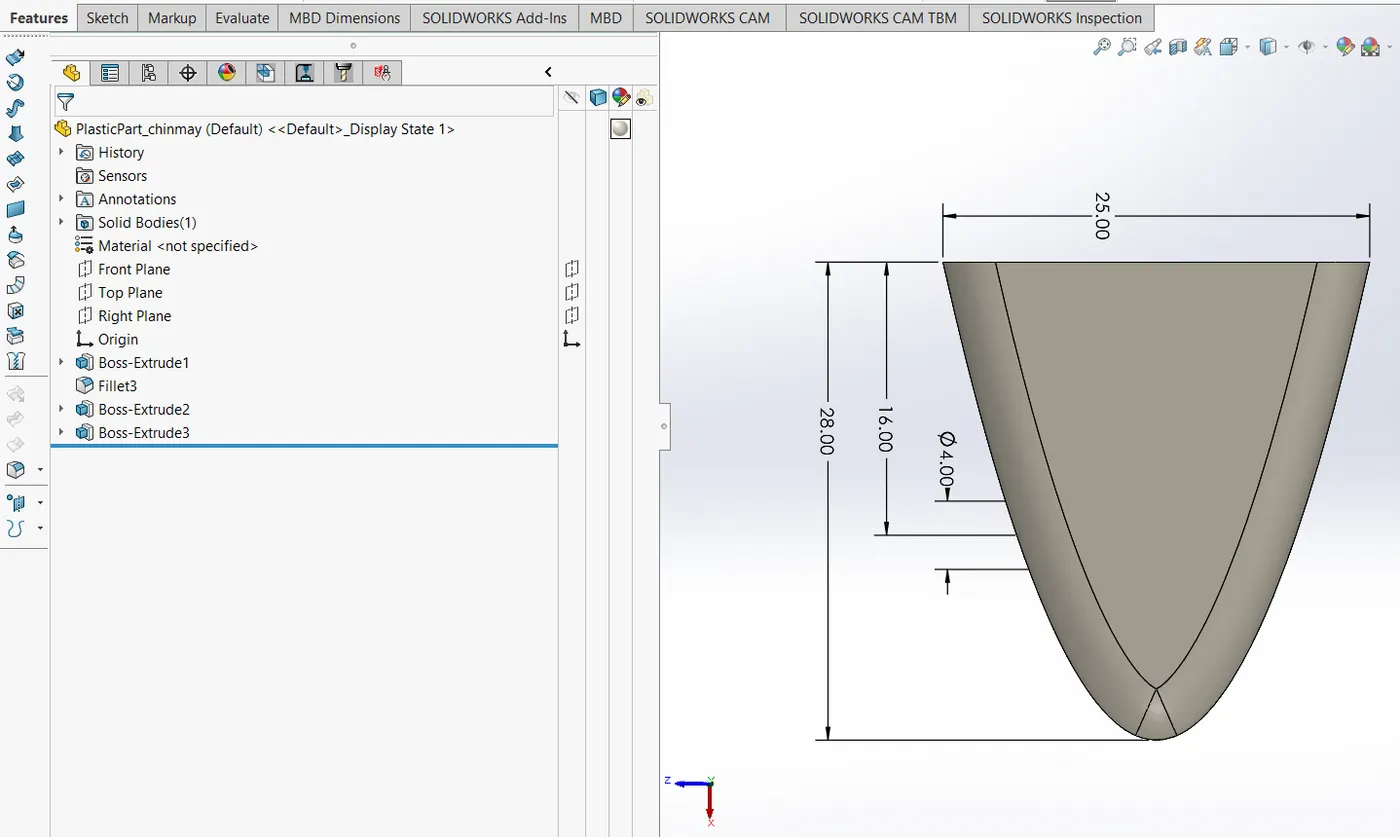
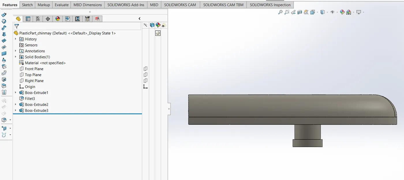
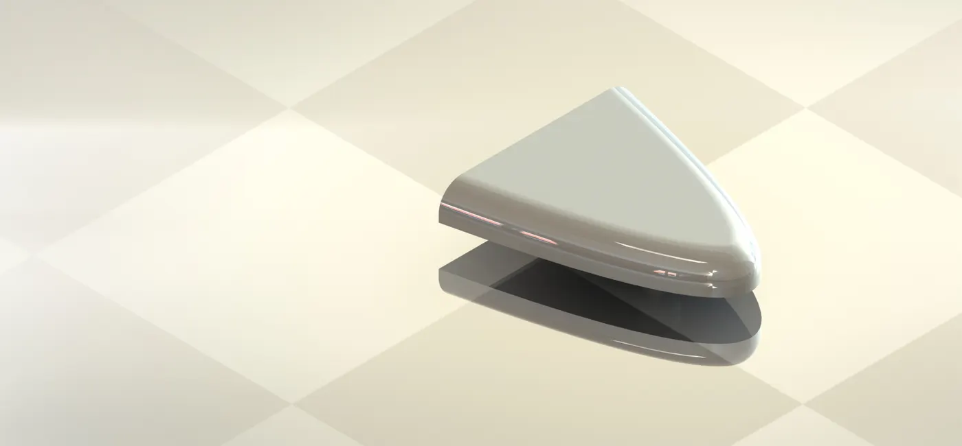
plastic part (plastic):
features used- sheet metal feaures are mainly used here - boss-extrude, fillet
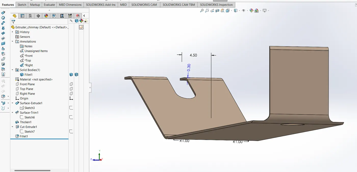
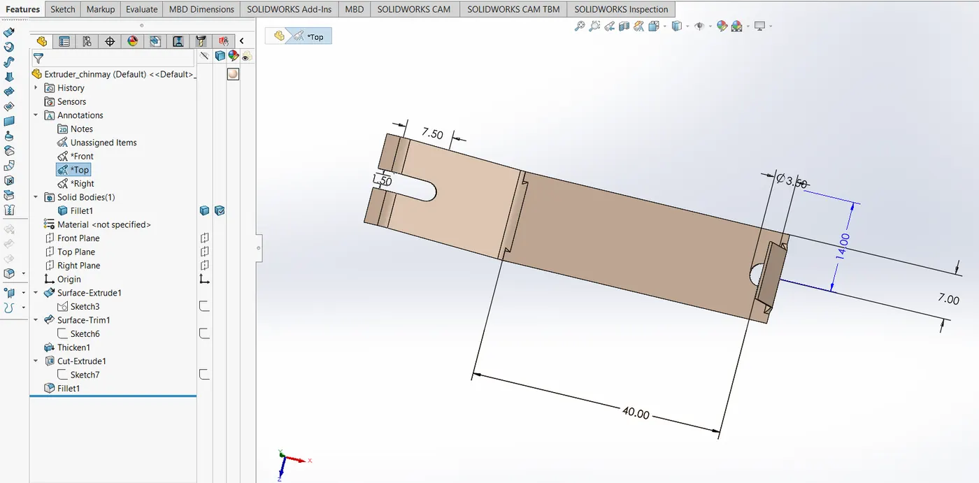
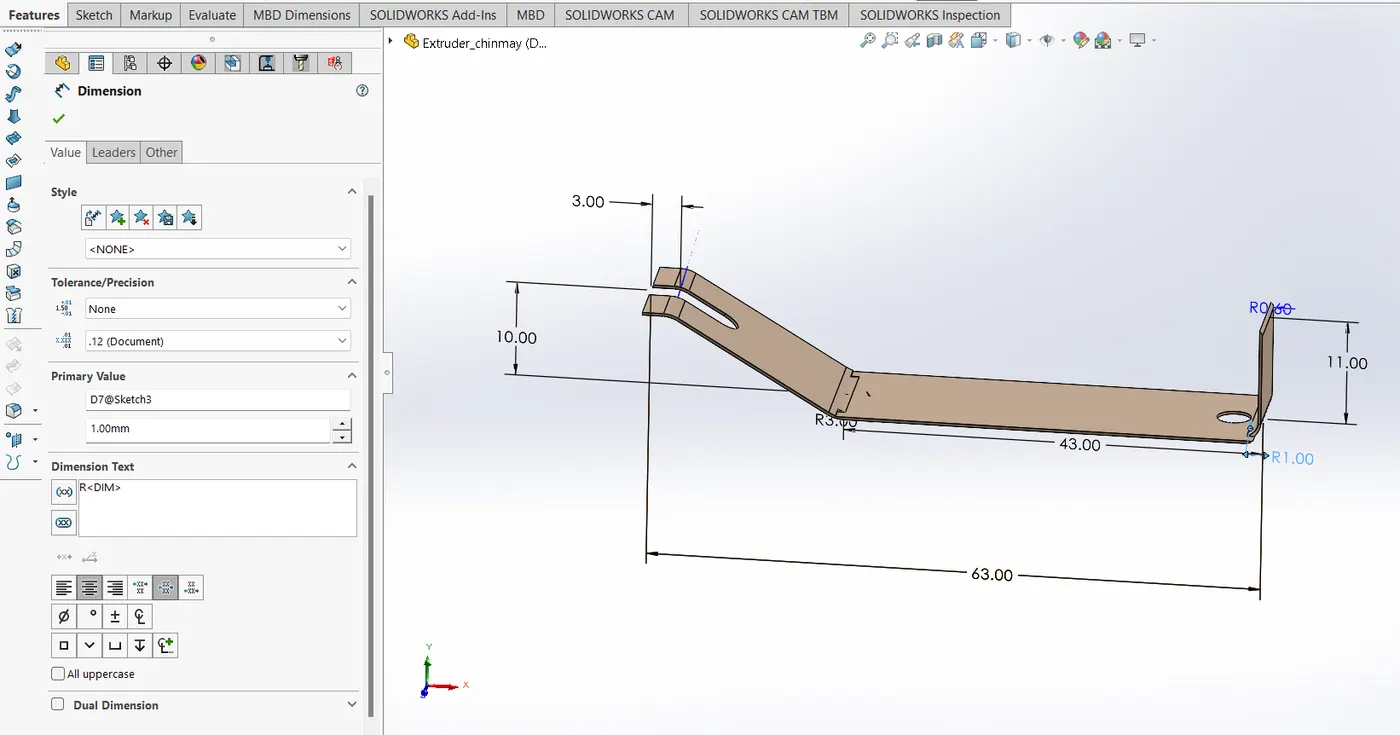
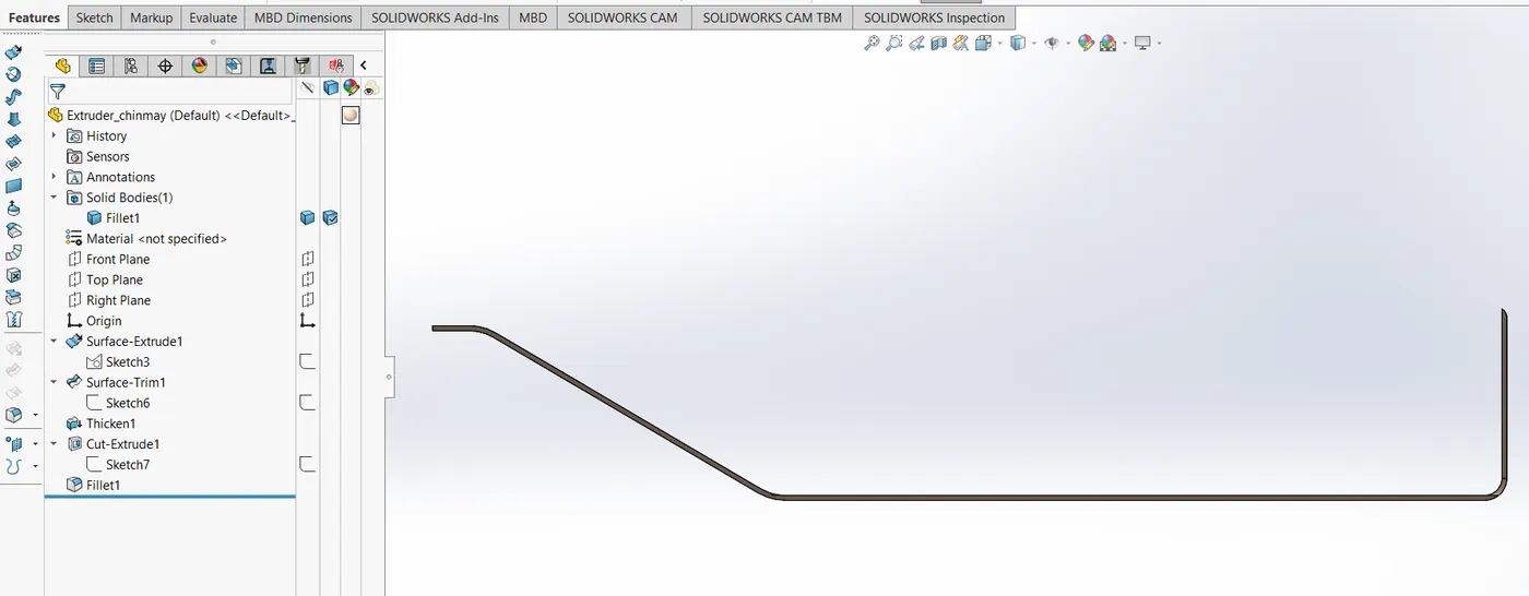
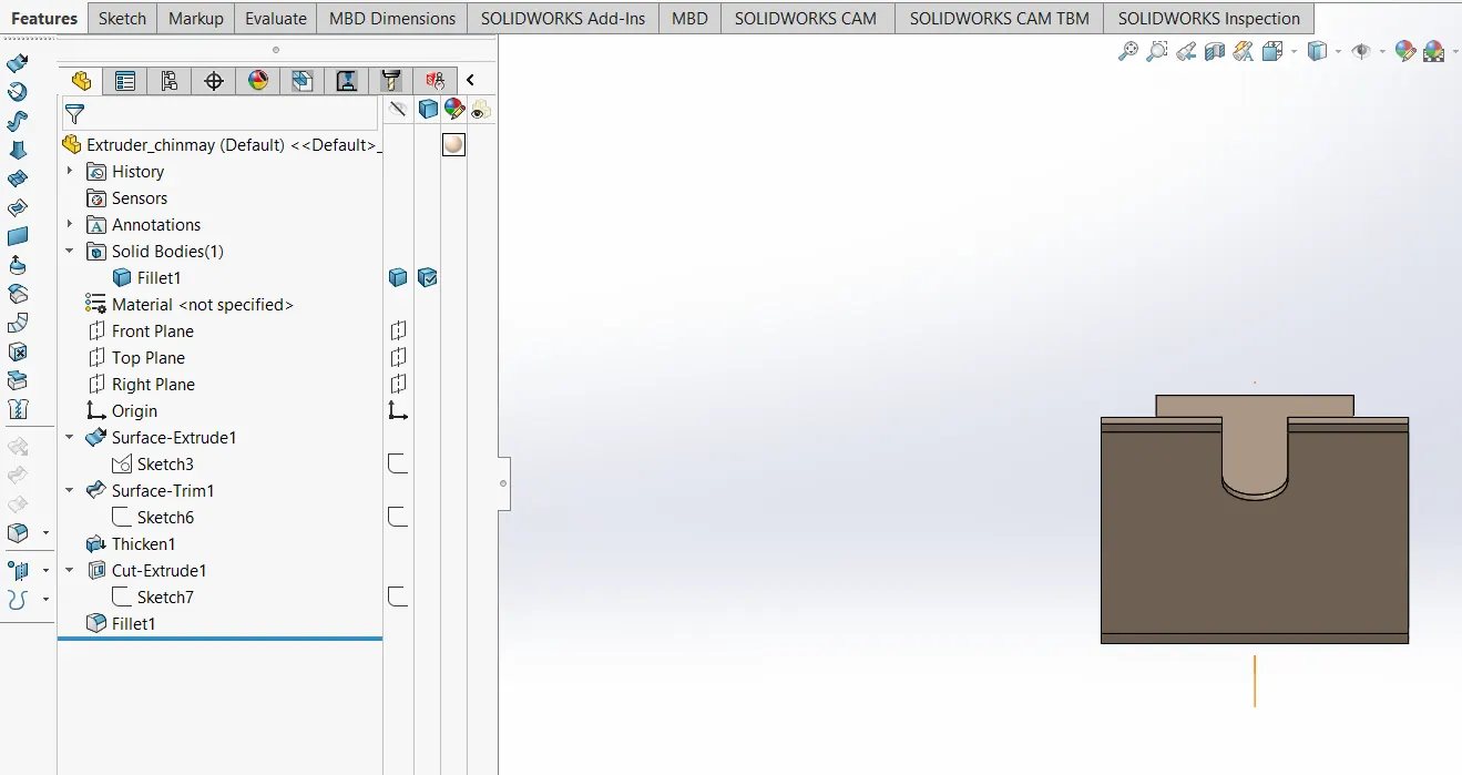
extruder (aluminium):
features used- sheet metal feaures are mainly used here - surface extrude, surface trim, thicken, fillet
feature explanations-
base flange - a starting sketch is converted into a base flange with a given thickness. this is similar to extrude but in teh context of sheet metal applications.
edge flange - after the base flange is set and reasy to use, edge flange is applied on it. it can be for any edge. more options are provided as to how you want the edge to be customised and built.
boss-extrude - extrudes a given geometry to a certain distance (more options are available).
fillet - smoothes out a sharp edge taking input a radius.
cut-extrude - cuts a solid when a geometry and distance (more options are available) is given as input.
Upload parts
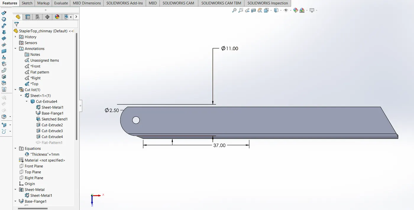
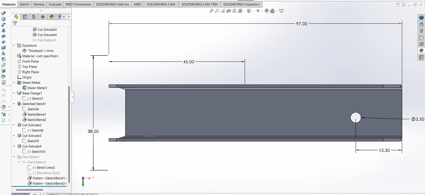
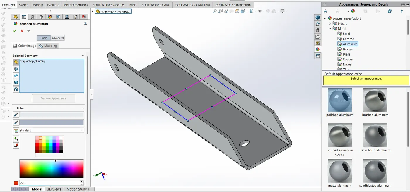
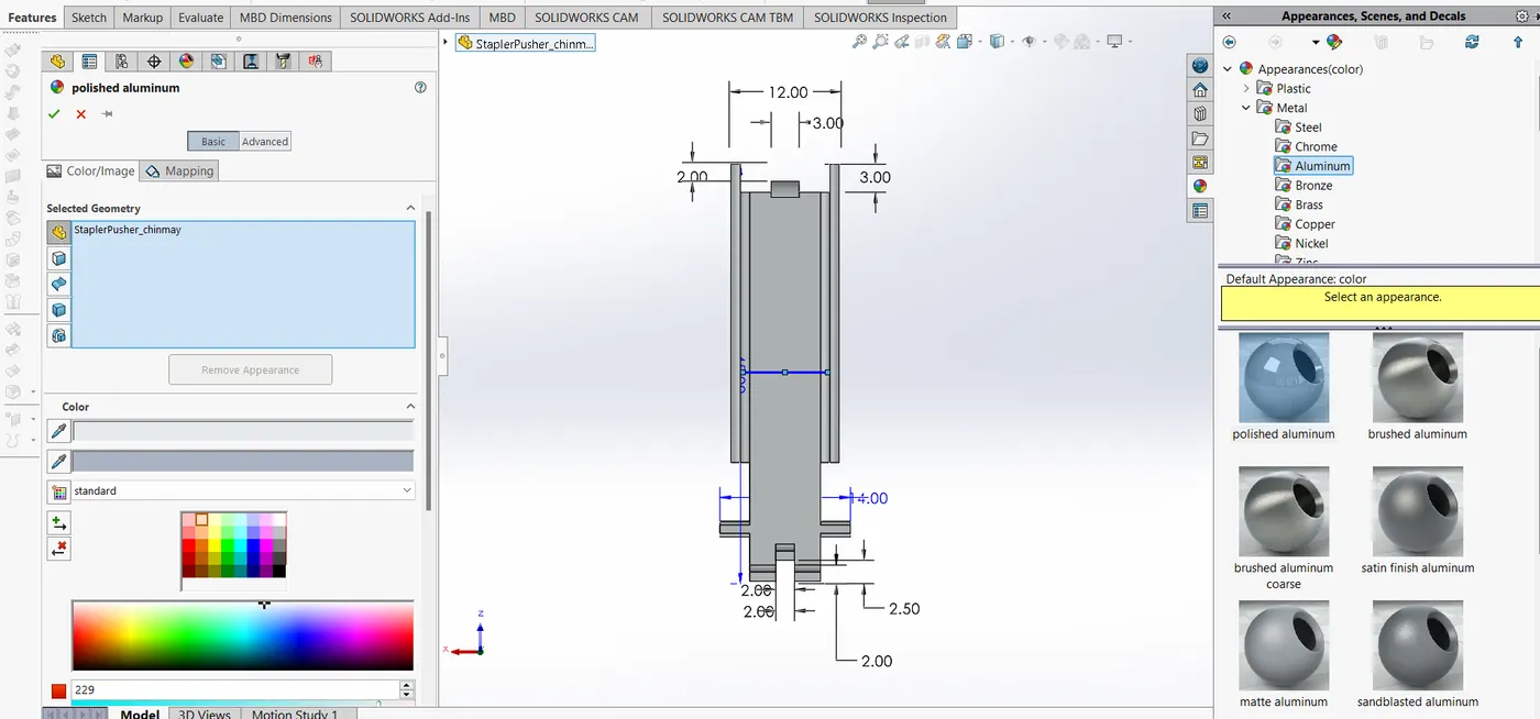
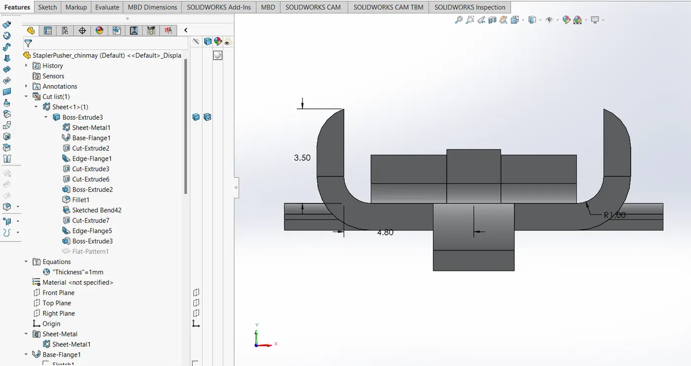
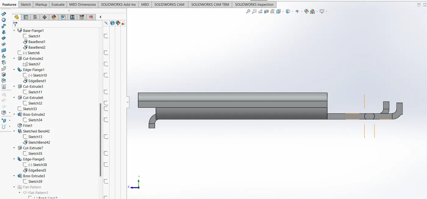
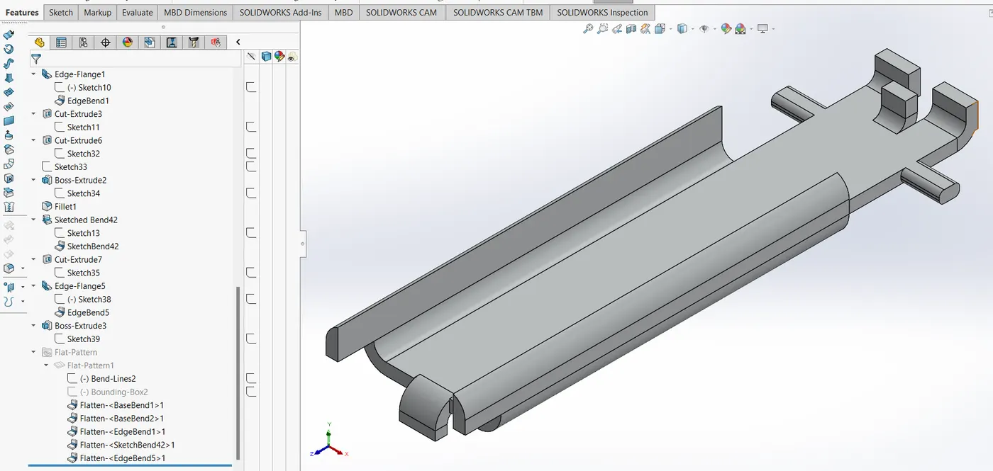
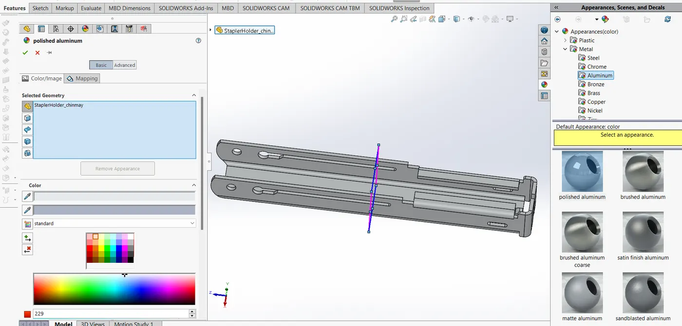
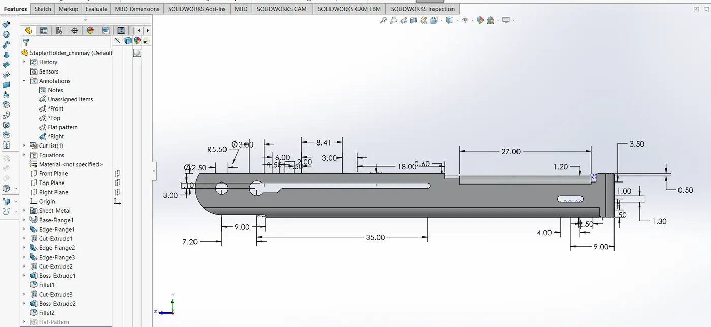
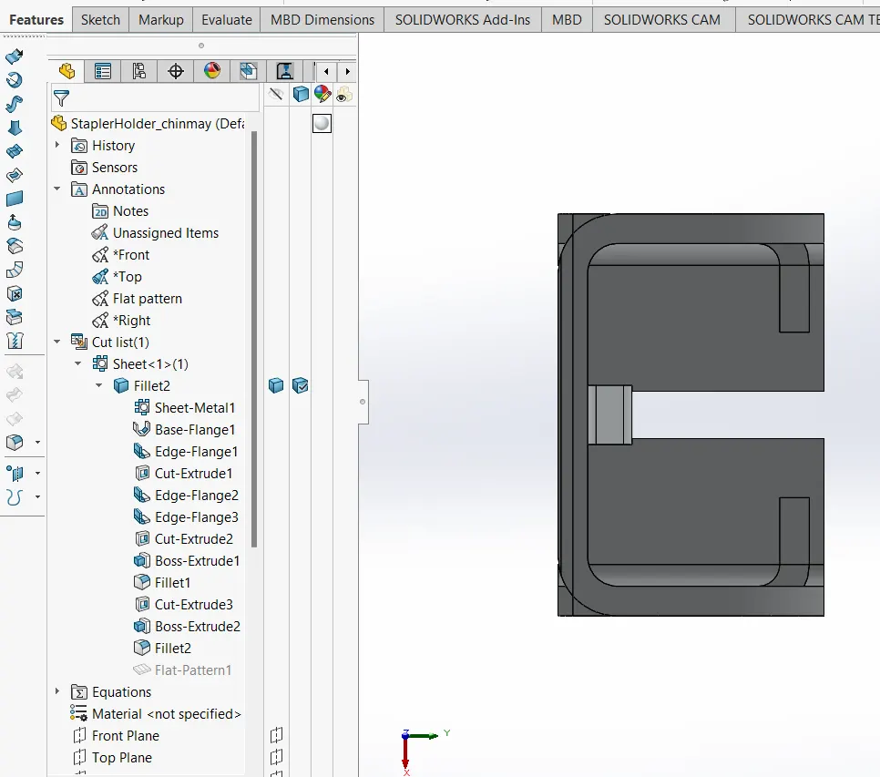
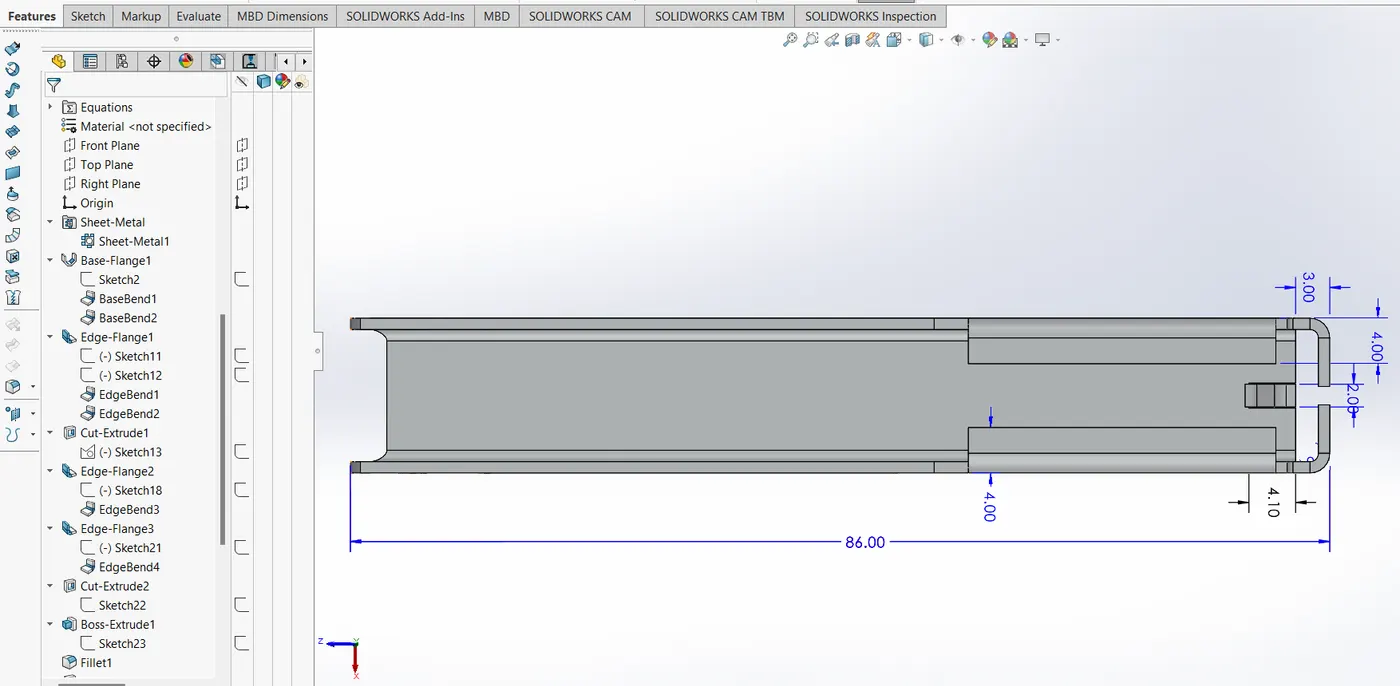
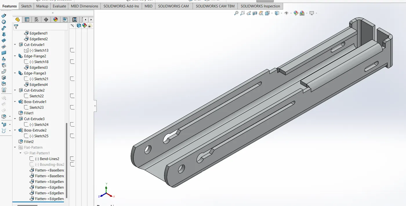
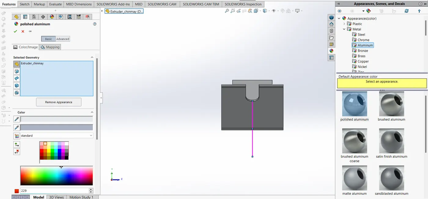
Upload a min of five screenshots of Assembly Model in the report. (For eg:-Front View, Side View, Isometric View, Camera Setup View and the Top View)
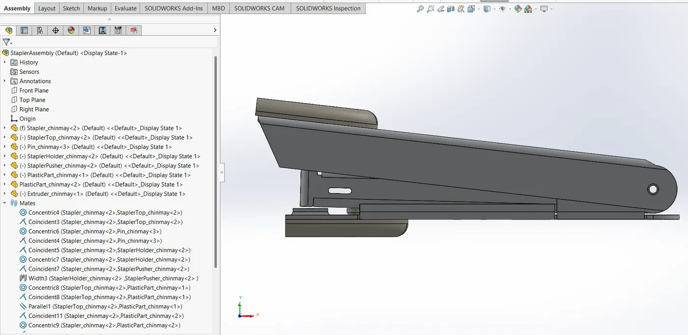
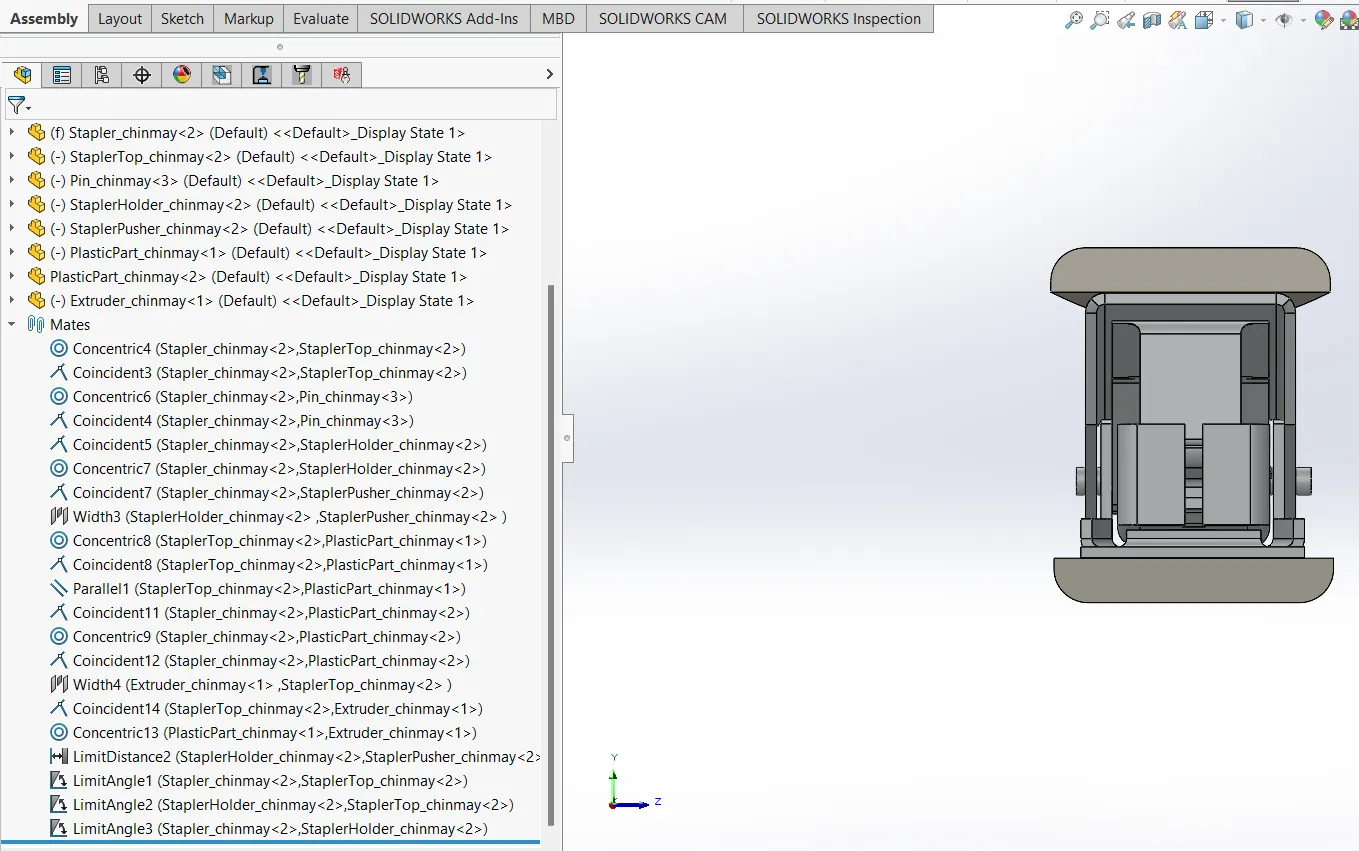
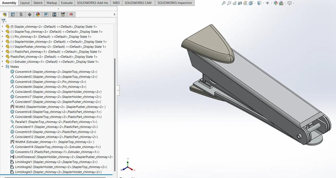
Attach Detailed Rendering Images of Assembly (If possible you can do the rendering of each part and attach snaps of same in report.)
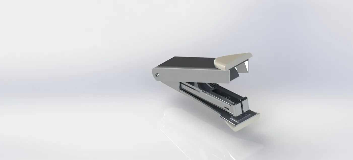
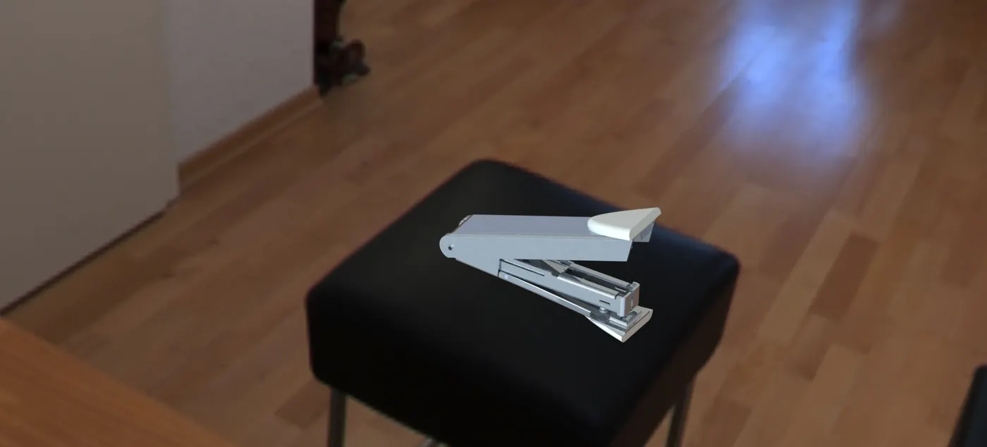
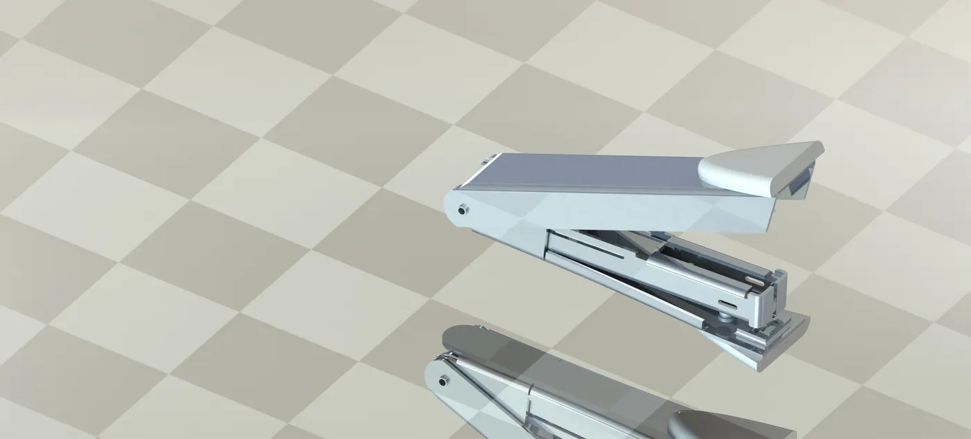
Part renders
Conclusion
A Stapler is designed in solidwoks from scratch on the basis of research on its geometry and dimensions. parts are generated and assembled in Solidworks assembly. Rendering of the parts and assembly is done using PhotoView 360.
the parts and assembly is attached in a zip file.
the final presentation is also attached.