FINAL INDEPENDENT PROJECT
HYDRAULIC HAND FORKLIFT
Aim:
- To create model and assemble the Hydraulic hand forklift assembly and analyze the piston & fork movement.
Objective:
- To create the 3D part of the Hydraulic hand forklift parts using part workbench.
- Then assemble the parts of forklift assembly using assembly workbench.
- Simulate the piston & forklift movement to the required angle value using motion analysis workbench.
- solve for the maximum displacement of piston & fork movement as required.
Theory:
- A hydraulic forklift is a machine that uses hydraulic lifting devices to raise or lower heavy objects.
- Hydraulic pistons are cylinders that are filled with a liquid, usually some type of oil, that can be pressurized to expand or depressurized to contract.
- A hydraulic forklift will use more than one cylinder mounted on the machine to lift a fork mechanism, which generally features two blades or tines, which slide into a pallet.
- A forklift can lift objects without a pallet, though the pallet makes lifting more stable and safer.
- Most hydraulic forklift models feature a drive system, and the driver will sit in or on the unit.
- Some models require the driver to walk behind the unit, controlling the hydraulic forklift using a hand yoke or lever.
- The tires of the lift can either be pneumatic tires filled with air or solid rubber tires.
- The type of tires used on the lift will depend on where the lift is most likely to be driven: a lift with solid rubber tires will usually only be used on flat surfaces such as warehouse floors, while pneumatic tires will be used outdoors or on uneven surfaces.
- The design of the hydraulic unit of the forklift will vary depending on the size and function of the lift.
- Many hydraulic forklift models feature a vertical lift system that raises the forks straight up.
- Other models may feature a telescoping boom arm that extends upward and outward from the body of the machine.
- This latter model is often known as a telehandler, and it is used for lifting objects much higher or farther out than a standard vertical lift model can accommodate.
- Forklifts can be powered in several ways: smaller models are often powered with electricity and will feature one or more batteries to control operations.
- Larger forklifts may feature gasoline powered engines for more power and torque.
- The largest versions of the hydraulic forklift will be diesel powered for the most power and torque.
- Diesel lifts are usually only used outdoors or in very well-ventilated areas, since diesel engines can produce a significant amount of exhaust; they also tend to be quite noisy and can make working conditions quite difficult when used indoors.
- Narrow forklifts are often used in warehouses or even retail establishments that have narrow aisles; these are usually electric-powered, though some are gas-powered as well.
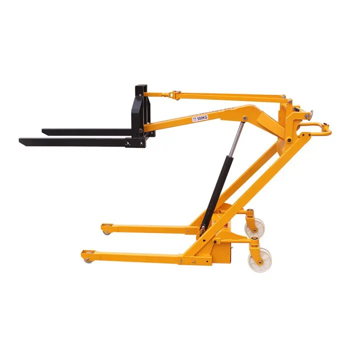
Parts of Hydraulic hand forklift:
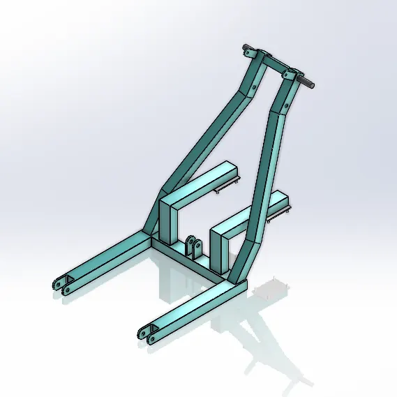
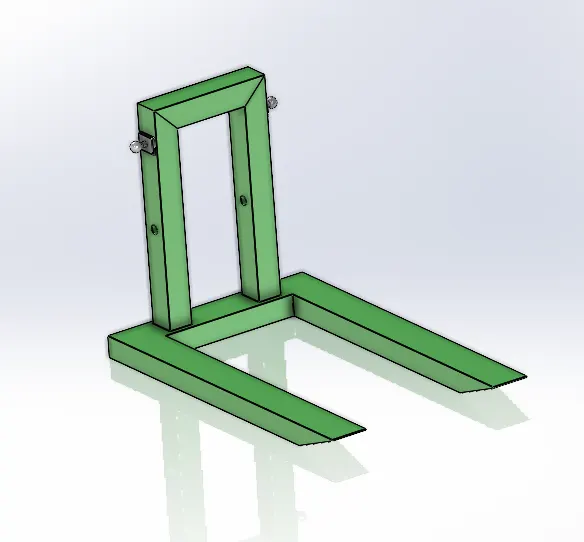
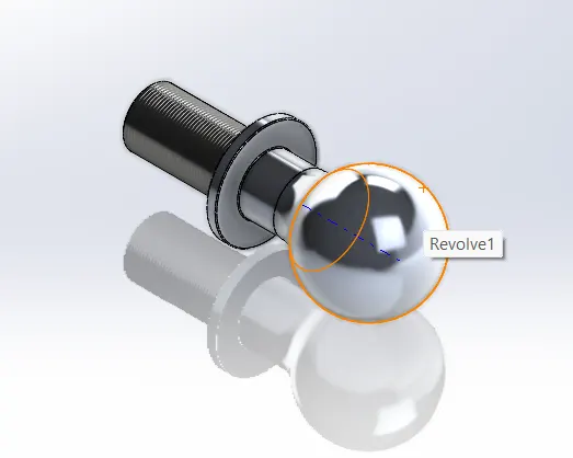
The required parts are created with the proper dimensions using part modelling workbench in SolidWorks software.
Base frame:
Lifting arm:
Ball end:
Connecting arm:
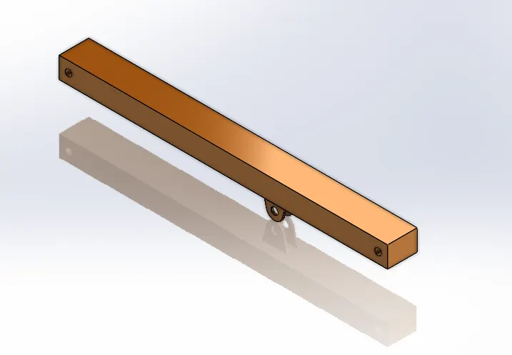
Cylinder:
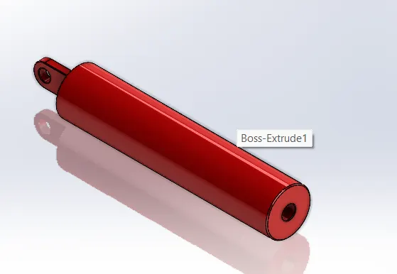
Front wheel:
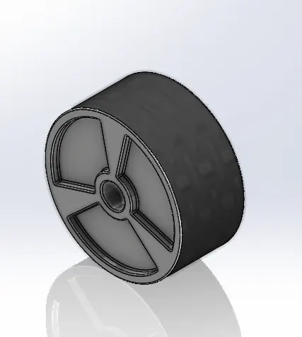
Piston:
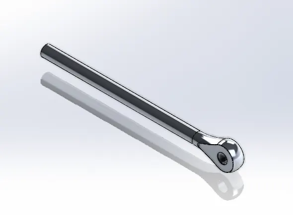
Rear wheel:
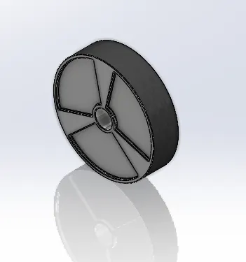
Rear wheel mount:
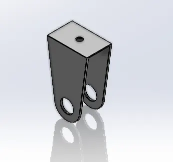
Rectangular plate:
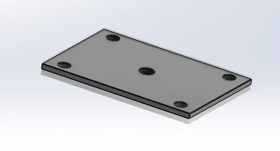
Rod:
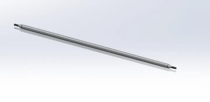
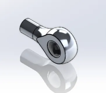
Rod end:
Fastners:
- A fastener is a broad range of mechanical tools/elements used to hold two or more objects together as a rigid attachment. Fasteners allow for the separation or dismantling of the pieces without suffering any damage. However, they can be used as permanent joints as well. Screws, nuts, bolts, nails, washers, etc
Fastners used for Hydraulic hand forklift are,
- Connecting rod front pin
- Connecting rod rear pin
- Cylinder pin
- Front wheel pin
- Nut
- Piston pin
- Rear wheel mount pin
- Rear wheel pin
- Washer
Assembly of Hydraulic hand forklift:
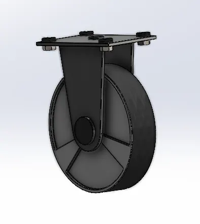
Rear wheel assembly:
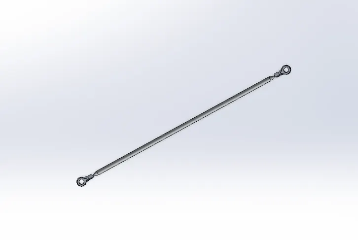
Anti rotation rod assembly:
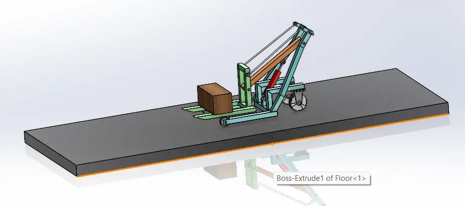
Hydraulic hand forklift assembly:
Motion analysis:
- The next step is to analysis the Hydraulic hand forklift assembly using the motion analysis workbench in SolidWorks. To analysis the Linear, angular displacement of the piston and the fork.
- And also, reaction force of lift arm & connecting rod.
Starting setup for motion analysis:
- Motion setup frame rate set as 60fps for this setup.
- Attach the linear motor to the piston.
- The motor speed set as 15mm/sec rpm.
- Make contact between all parts in the assembly.
- Total time of analysis in 5 second.
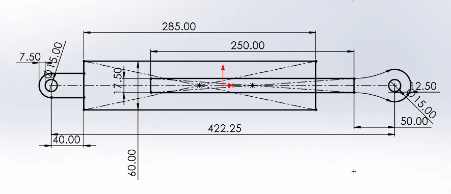
Case 1: (250 mm)
- For this case 1 the piston distance is maintained as 250 mm and then run the simulation by using the above motion study stating setup.
Result plots:
Linear displacement
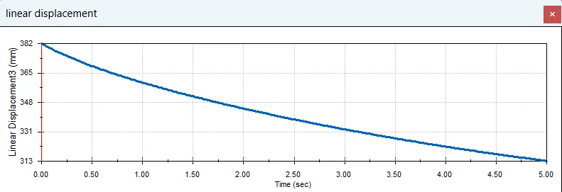
- This plot is drawn for the linear displacement of the piston from the cylinder.
- Time (sec) in x direction, total duration is 5 sec. And linear displacement in y direction.
- By this plot the displacement by the piston is from 313 to a maximum of 382.
- So the total displacement by the piston is 69 mm.
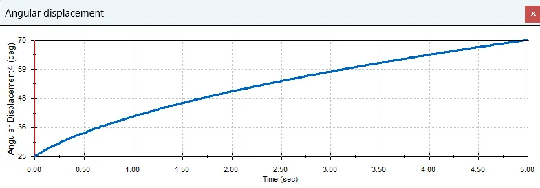
- This plot is drawn for the angular displacement of the piston and the connecting rod.
- Time (sec) in x direction, total duration is 5 sec. And angular displacement in y direction.
- By this plot the displacement by the piston and connecting rod is between 25 to 70 deg.
- So, the total displacement between them is 95 deg.
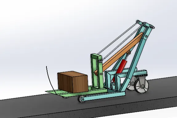
Case 2: (260mm)
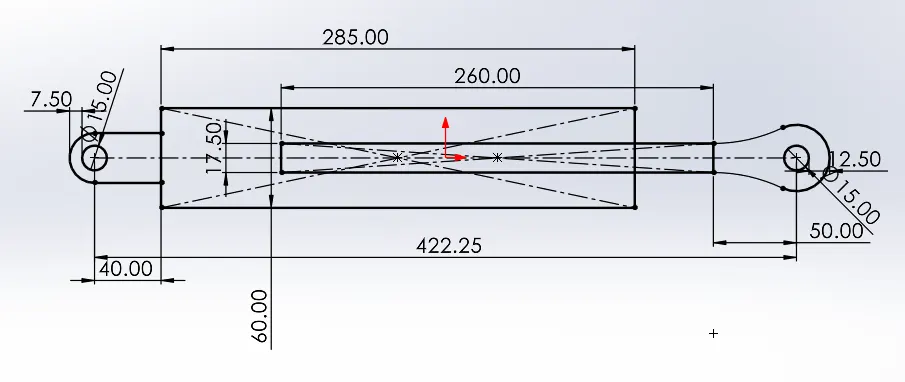
- Previous case 1 the angle value is not satisfied so here we increase the distance furthermore.
- For this case 1 the piston distance is maintained as 260mm and then run the simulation by using the above motion study stating setup.
Linear displacement
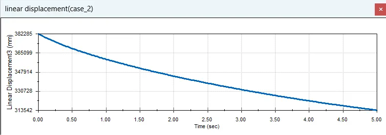
- As the length is increased there is increase in displacement .
- So, it makes no difference in increasing the value.
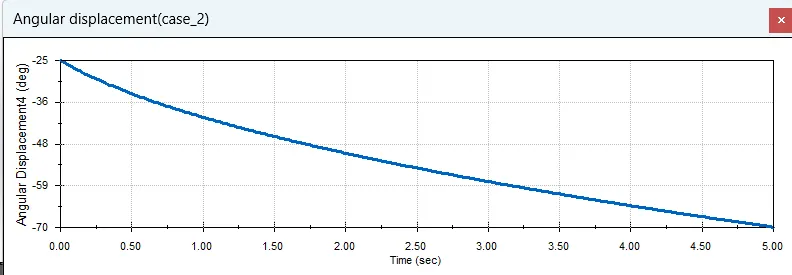
- This plot is drawn for the angular displacement of the piston and the connecting rod.
- Time (sec) in x direction, total duration is 5 sec. And angular displacement in y direction.
- By this plot the displacement by the piston and connecting rod is between -70 to -25deg.
- So, the total displacement between them is 95 deg.
Observation and result
- From this Hydraulic hand forklift motion study, we can understand that the piston distance is not much related to the angle.
- When the piston distance is increased only the linear displacement increase.
- And due to the increase in length the lift height is increased