FINAL INDEPENDENT PROJECT
Phase 1:
Objectives of the Design
1. Accurate 3D Modeling
- Objective: Create precise 3D models of each engine component.
- Details: Using SolidWorks design tools to model each part to exact specifications, ensuring that all dimensions and features are accurately represented.
- Tools Used:
- Sketch tools for initial profiles.
- Extrude, Revolve, Sweep, and Loft features for creating 3D shapes.
- Fillet, Chamfer, and Hole Wizard for detailed features.
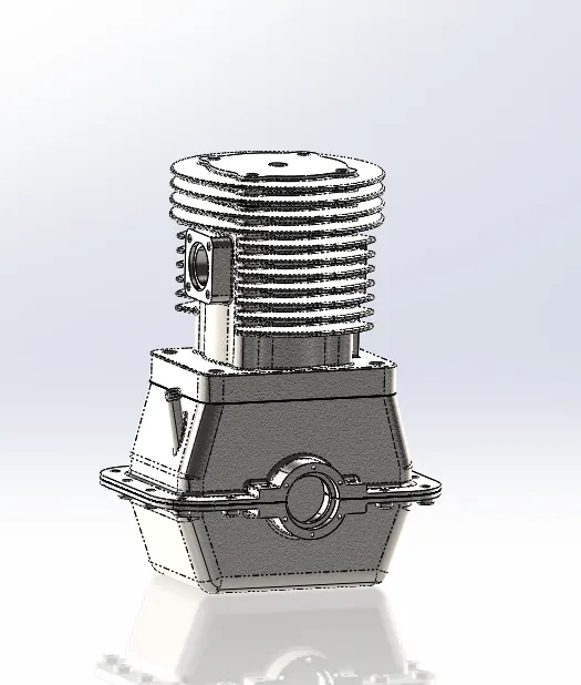
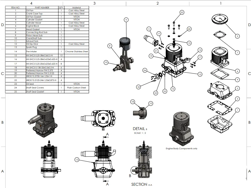
- Outputs: Detailed 3D models of the cylinder, piston, connecting rod, crankshaft, camshaft, and other related components.
- Objective: Assemble the individual components to form the complete engine.
- Details: This involves using mating tools to ensure that all parts fit together correctly and move relative to each other as they would in a real engine.
- Tools Used:
- Mate tool for aligning and connecting parts.
- Advanced Mates for simulating motion and interactions.
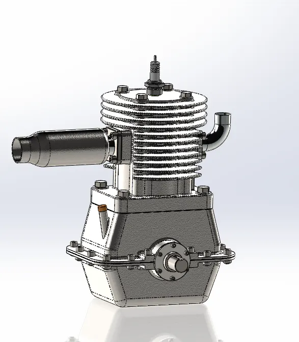
- Outputs: A fully assembled 3D stroke engine model with all components correctly positioned and constrained.
- Objective: Demonstrate the basic motion of engine components.
- Details: This involves setting up a basic motion study to show how the piston moves within the cylinder, how the connecting rod transfers this motion to the crankshaft, and how the crankshaft rotates.
- Tools Used:
- Motion Study feature in SolidWorks.
- Basic motors and constraints to simulate the engine's motion.
- Outputs: A visual simulation of the engine's moving parts, illustrating the basic operational cycle.
1. Visualization and Concept Validation
- Significance: Creating a detailed 3D model helps visualize the engine’s design and validate the concept before moving to the production phase. This ensures that the design is feasible and meets the intended functional requirements.
- Significance: The detailed SolidWorks model is a valuable tool for communicating the design to stakeholders, including engineers, designers, and manufacturers. It aids in collaborative efforts by clearly and precisely representing the engine.
- Significance: The initial 3D design allows for easy modifications and iterations. Engineers can refine the design by adjusting dimensions, geometry, and assembly constraints, producing an optimized final product.
- Research: Studied the structure and function of stroke engines, focusing on components and their interactions.
- Sketching: Created initial sketches of the engine layout, identifying key dimensions and relationships between components.
- Specifications: Defined the specifications and constraints for each component based on typical stroke engine designs.
- Sketching the Cylinder:
- Created a new part file.
- Sketched a cross-section of the cylinder on the front plane.
- Used the Extrude Boss/Base feature to give the cylinder its three-dimensional shape.
- Adding Details:
- Added cooling fins, ports, and mounting holes using the Extrude Cut and Fillet features.
- Creating the Assembly File:
- Created a new assembly file.
- Inserted the cylinder part as the base component.
- Inserting and Mating Components:
- Inserted the piston into the cylinder, using the Mate feature to constrain its movement along the cylinder axis.
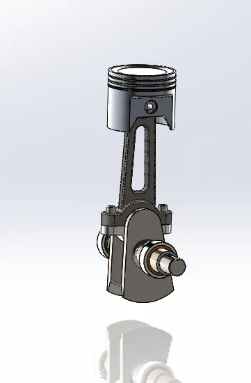
- Inserted the connecting rod and mated it to the piston and crankshaft.
- Positioned the crankshaft and added rotational constraints to ensure realistic movement.
- Added the camshaft and ensured proper timing with the crankshaft using gear mates.
- Testing the Assembly:
- Simulated the engine operation by rotating the crankshaft and observing the movement of the piston, connecting rod, and camshaft.
- Ensured that all components moved smoothly and without interference.
- Interference Detection:
- Used SolidWorks’ Interference Detection tool to identify and resolve any clashes between components.
- Adding Fasteners and Accessories:
- Added bolts, nuts, and other accessories using the SolidWorks Toolbox.
- Material Assignment and Rendering:
- Assigned appropriate materials to each component for accurate mass properties and visual appearance.
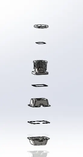
- Created renderings and exploded views for documentation and presentation.
- Documentation:
- Created detailed drawings of each component and the overall assembly.
- Included dimensions, tolerances, and annotations.
- Simulation:
- Conducted basic motion analysis to verify the operation of the engine.
- Review and Iteration:
- Reviewed the design for any improvements and made necessary adjustments.
Introduction
This report outlines the design process of a stroke engine created using SolidWorks. The objective was to design a functional model that accurately represents the components and operations of a stroke engine. This includes the assembly of parts such as the cylinder, piston, connecting rod, crankshaft, and camshaft, and ensuring their correct interaction to simulate engine operation.
Design Process
1. Planning and Conceptualization
Before beginning the design in SolidWorks, the following steps were taken:
2. Creating Individual Components
Each engine component was designed separately, ensuring accurate dimensions and functionality. Below are the steps for designing major components:
Cylinder
Piston
o Created a new part file.
o Sketched the piston profile on the front plane.
o Used the Revolve Boss/Base feature to create the piston shape.
o Added the piston rings and wrist pin holes using the Extrude Cut and Hole Wizard features.
Connecting Rod
o Created a new part file.
o Sketched the side profile of the connecting rod on the front plane.
o Used the Extrude Boss/Base feature to create its 3D shape.
o Added the crankshaft and piston pin holes using the Hole Wizard.
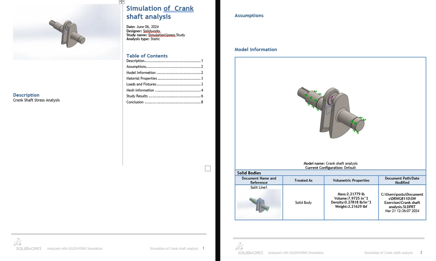
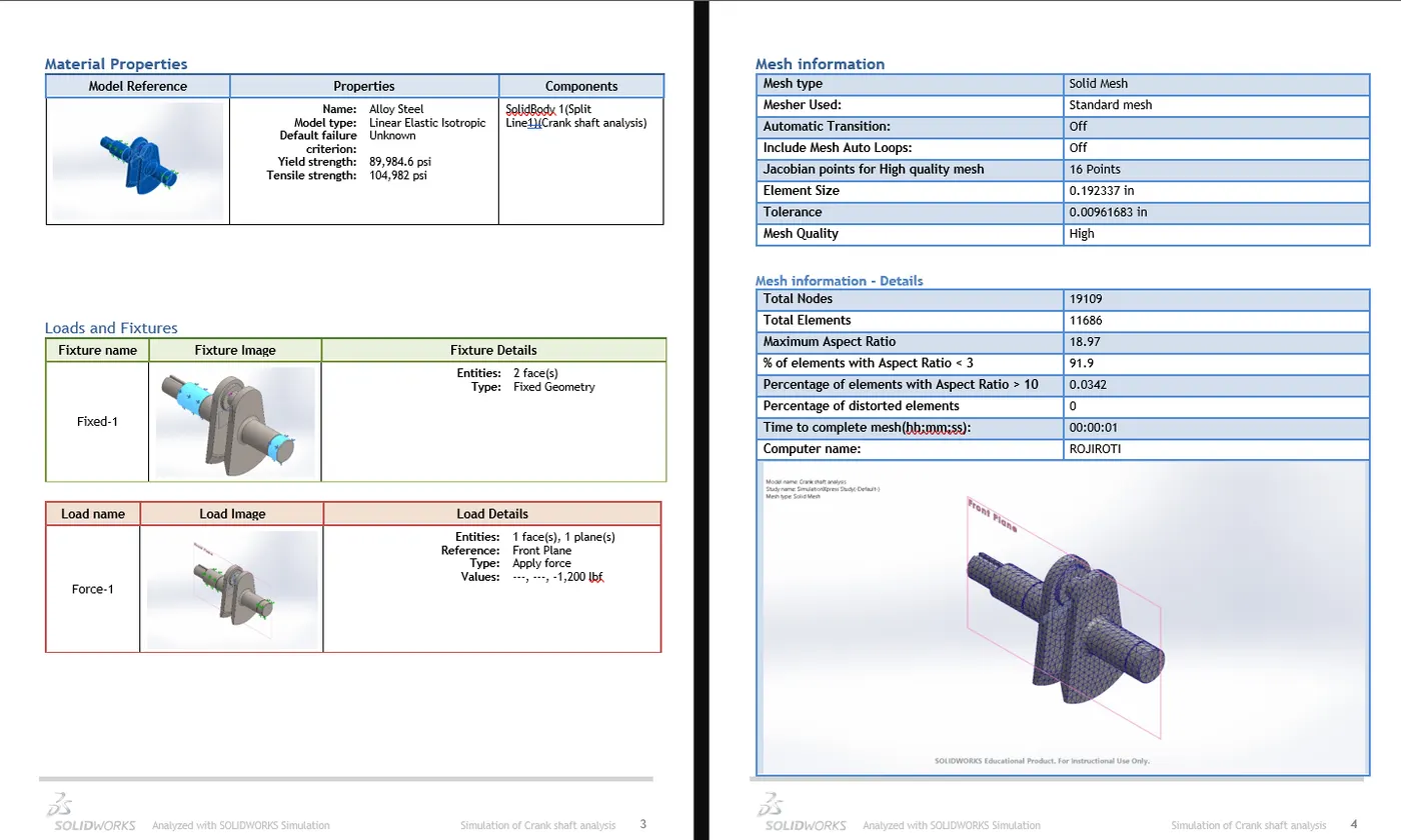
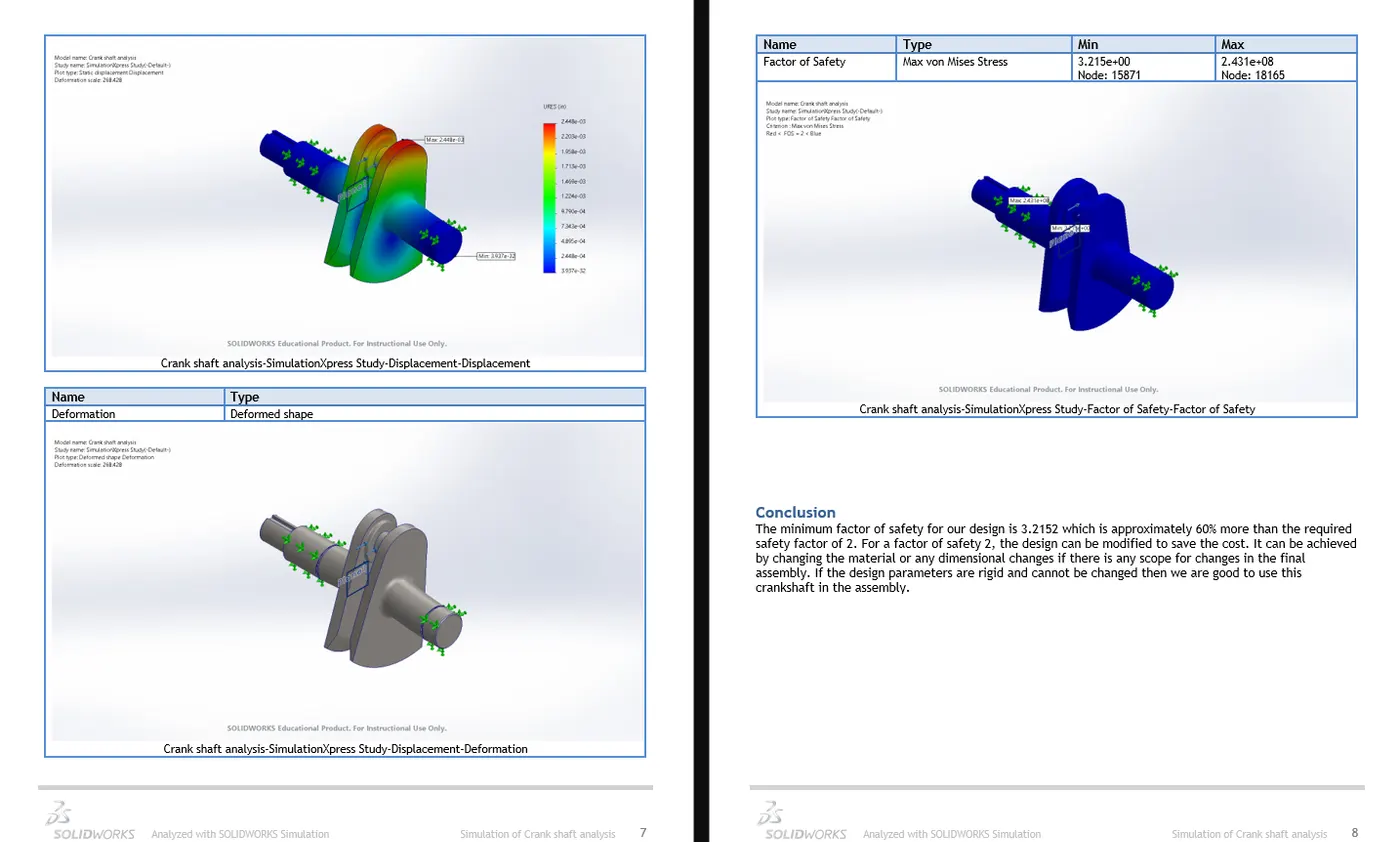
Crankshaft
o Created a new part file.
o Sketched the crankshaft profile on the front plane.
o Used the Revolve Boss/Base feature to generate the main shaft.
o Added the crank throws and counterweights using the Extrude Boss/Base and Fillet features.
Camshaft
o Created a new part file.
o Sketched the camshaft profile on the front plane.
o Used the Revolve Boss/Base feature to create the camshaft shape.
o Added the cam lobes using the Extrude Boss/Base feature, ensuring correct placement and orientation.
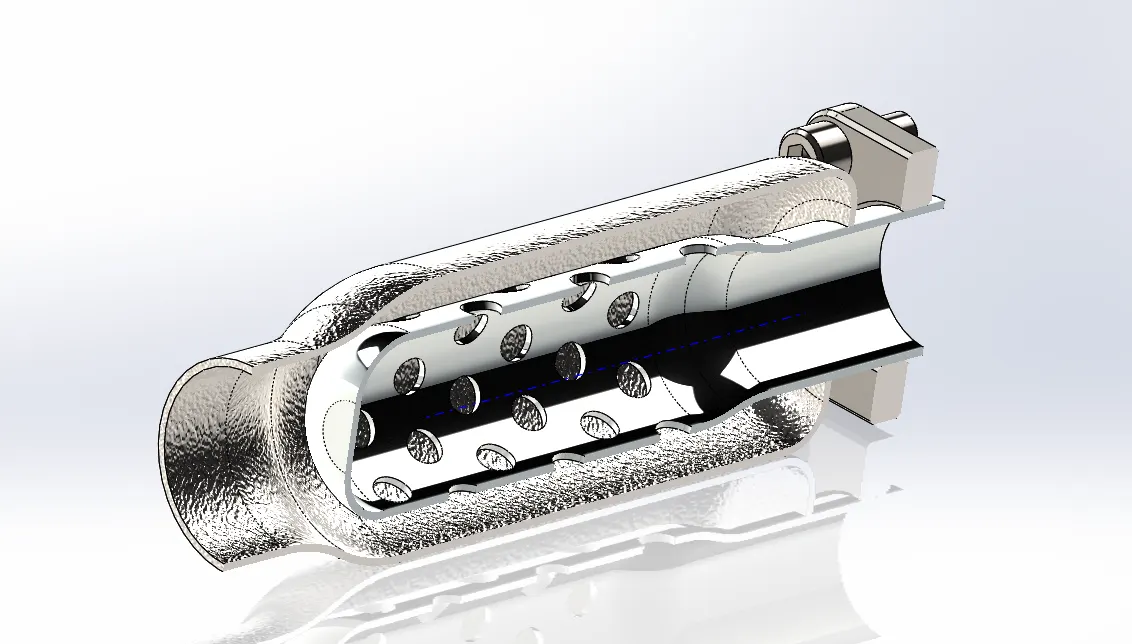
Exhaust
o Exhaust subassembly is made of a muffler, cover, and base.
o Used the Revolve Boss/Base feature, wrap command, and circular pattern to create Exhaust.
Other components: Oil Pan, Gaskets, Spark Plug
3. Assembling the Engine
Once all individual components were designed, the assembly process began:
4. Detailing and Refining
5. Finalizing the Design
Conclusion
Designing a stroke engine in SolidWorks involved planning, creating individual components, assembling them, and ensuring proper interaction. The resulting model accurately represents the functionality of a real stroke engine, providing a valuable tool for further analysis and education. This project significantly enhanced skills in 3D modeling, assembly, and simulation within SolidWorks.