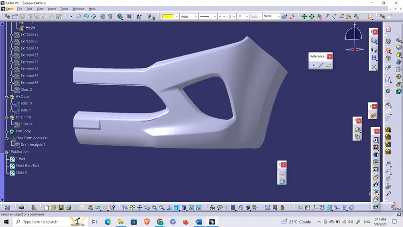
Week 9 - Challenge 3 - Bumper
Draft Analysis
Draft analysis is a technique to verify the tool ability or manufacturability of the component designed. In molding, a draft has to be given to the component to ensure easy removal of the manufactured part between the core and cavity. This draft is to be made sure while designing the component and draft analysis verifies it. If the component clears the draft analysis, it is ok to go.
Draft analysis and tooling axis of Bumper
To create a tooling axis:
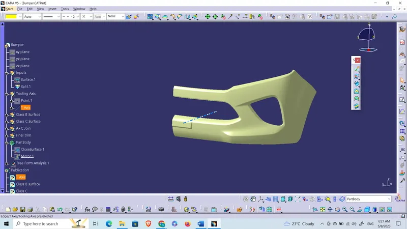
- By analyzing the class A surface the tolling axis is to be made in the direction of the X-axis.
- Insert another geometrical set with the name tooling axis and insert a point with a point-type curve. Select the centre of the curve for the placement of the point.
- Now construct a line with point and direction type. Chose the point we just placed on the center of the curve and chose the direction as the X-axis.
- On performing the draft analysis, the class A surface is clearing the draft analysis. So, this line is the TOOLING AXIS.
This axis gives us the direction along which the core and cavity have to open to take out the molded component.
How to do Draft Analysis:
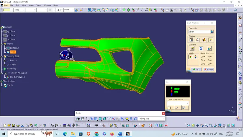
- Chose the view mode to shade with material mode.
- Now select the feature draft analysis tool and select the compass symbol from the direction toolbar. Drag the compass to the tooling axis and drop it. Click anywhere on the class A surface.
- The whole class A surface turns to green color which shows the component has cleared the draft analysis and the component has a 3-degree draft as per design requirements.
Class B surface
Class B surface is a surface which contains all the engineering features of a component. Unlike Class A surface it is not visible and doesn’t contribute to the aesthetic look of a component.
Creating Class B surface for Bumper
- Class B surfaces can be made by offsetting the class A surface. Extract the respective surfaces then offset them or the whole surface can be offset.
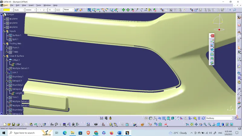
- Click on the offset command and select the class A surface. Chose the direction and give a offset value of 3mm. As a result of this, an offset surface with some open profiles would be formed. Now the task is to close the profiles by extrapolating and trimming them together.
Open Profile 1 and 2:
Open Profile 3:
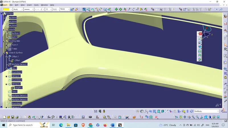
*Use multiple extract command to extract the surfaces as different entities. Because to extrapolate and then to trim them together we need different surfaces.
Class C surface
Class C surface is the surface that joins Class A and Class B surface.
Creating Class C surface for Brace Bracket
- To create the C surface, we are going to use the sweep command. This can be done by using the sweep command with reference to the draft direction and with reference to the surface.
With reference to the draft direction: Whenever the C surface is in a direction which is parallel to the tooling axis.
b. With reference to the surface: Whenever the C surface is perpendicular to the tooling axis. - In this case we need to use both approaches to make C surface.
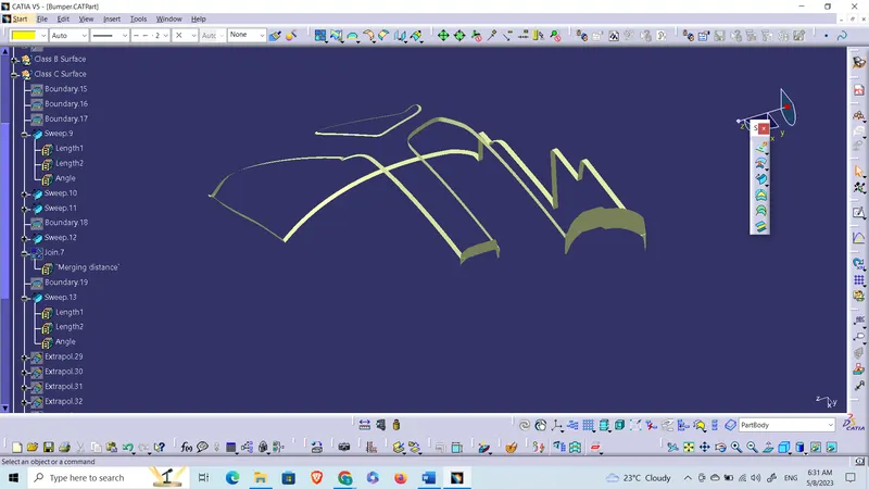
The final step is to close the surface in the part workbench. Toggle to the part workbench and select the close surface and the final component is deigned.
Repeat the draft analysis on the part with the same procedure as mentioned above.
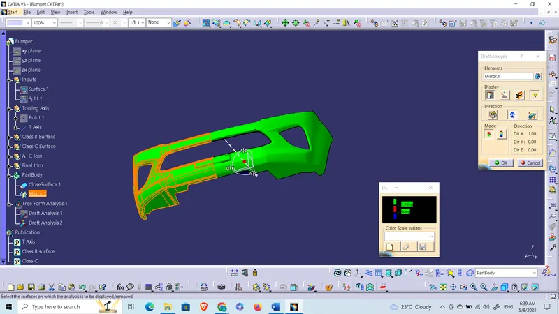
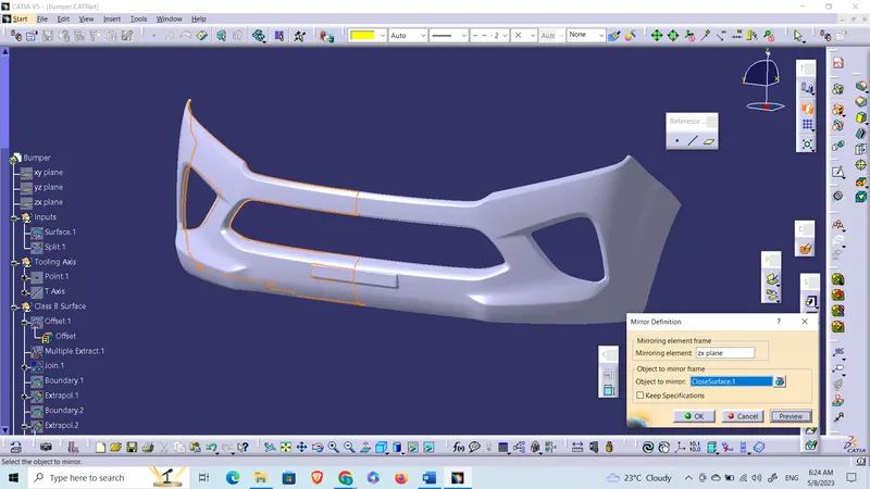
You can use the mirror command to auto-construct the left symmetrical part of the bumper.