Week 9 - Challenge 2 - Switch Bezel Design
Creation of Tooling Axis:
Step 1: Creation of Reference Point.
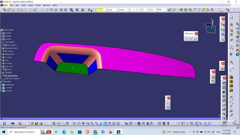
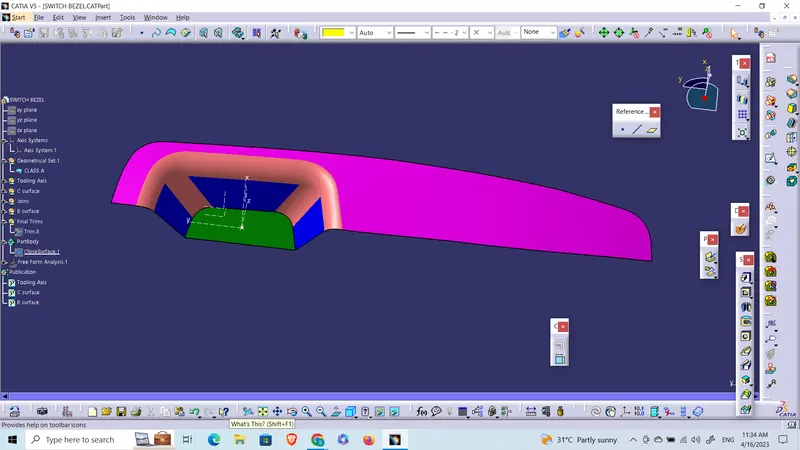
Step 2: Creation of Axis System at the reference point
Step 3: Creation of Intersections
Chose the surfaces that are not normal to Z direction and create intersections with the corresponding supporting planes.
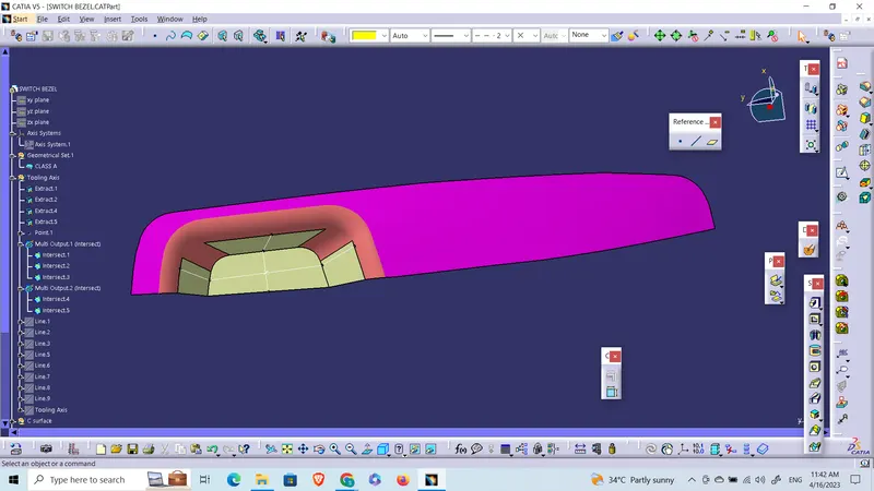
Step 4: Creation of Tooling Axis with Bisecting Lines
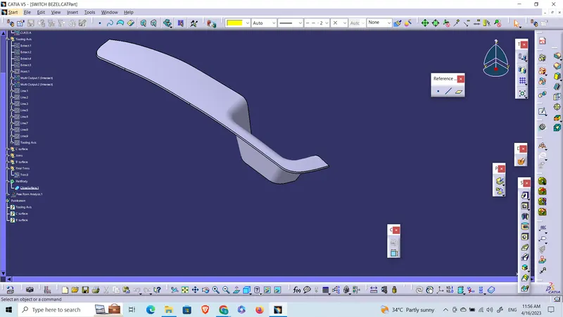
Now create bisecting lines with lines tangential to the surfaces on the intersections. And create a tooling axis with bisecting these two lines.
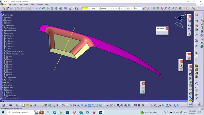
Drafting Analysis:
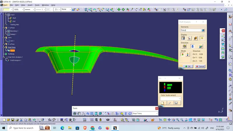
After the creation of the tooling axis, the closed surface is to be analysed for the surface draft. Chose the Draft analysis command and Click on the compass symbol. Drag the compass and drop it on the tooling axis. Now lock the orientation and click on the closed surface. The green colour all around shows the clearance of the draft analysis. In most cases, we can give a tolerance value of .1 in the draft angle in the analysis.