Photo Realistic Rendering
Title: Project report of Design of American Chopper in Solidworks.
Objective: Modeling and writing the Report on the Assembly of the Chopper Model.
Introduction: This project explains the assembly of the American Chopper and the rendering of the different views.
Methodology:

<!--[endif]-->
The parts of the American Chopper are modeled and assembled on SolidWorks. The assembly and parts are rendered using the add-in Photo View 360.
Description of Parts and features used in Part modeling along with rendered images:
<!-- [if !supportLists]-->1Chain:
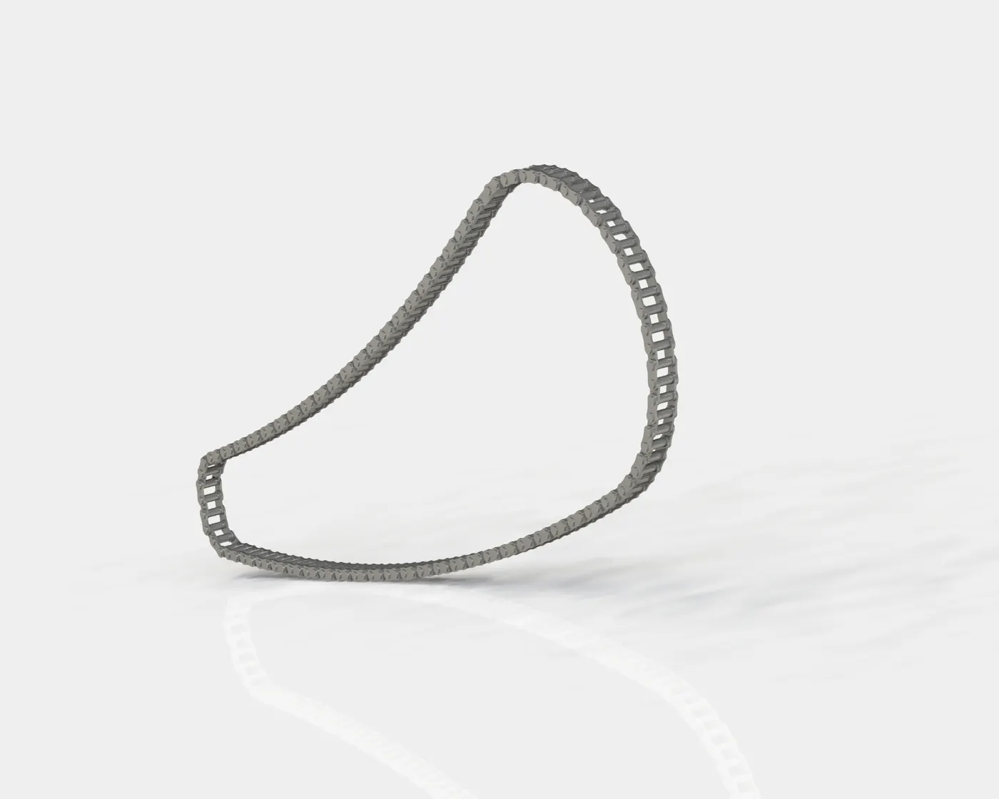
Features used:
<!-- [if !supportLists]-->· <!--[endif]-->Extrude boss.
<!-- [if !supportLists]-->· <!--[endif]-->Curve Driven pattern.
<!-- [if !supportLists]-->· <!--[endif]-->Blocks
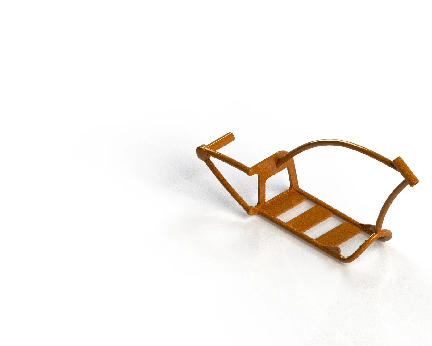
<!-- [if !supportLists]-->2 <!--[endif]-->Chassis
<!--[endif]-->
Features used:
<!-- [if !supportLists]-->· <!--[endif]-->Revolve Cut
<!-- [if !supportLists]-->· <!--[endif]-->Extrude boss.
<!-- [if !supportLists]-->· <!--[endif]-->Projected Curve
<!-- [if !supportLists]-->· <!--[endif]-->Trim entities
<!-- [if !supportLists]-->· <!--[endif]-->Swept boss
<!-- [if !supportLists]-->· <!--[endif]-->Split
<!-- [if !supportLists]-->· <!--[endif]-->Fillet
<!-- [if !supportLists]-->· <!--[endif]-->Combine
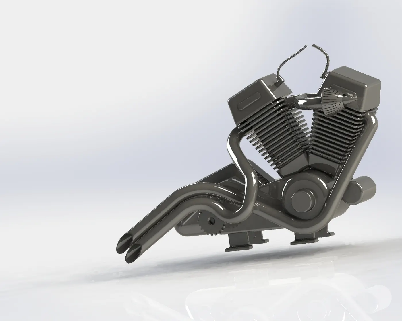
EEngine
<!--[endif]-->
Features used:
<!-- [if !supportLists]-->· <!--[endif]-->Trim entities
<!-- [if !supportLists]-->· <!--[endif]-->Revolve Boss
<!-- [if !supportLists]-->· <!--[endif]-->Extrude Cut
<!-- [if !supportLists]-->· <!--[endif]-->Offset entities
<!-- [if !supportLists]-->· <!--[endif]-->Fillet
<!-- [if !supportLists]-->· <!--[endif]-->Projected Curve
<!-- [if !supportLists]-->· <!--[endif]-->Composite Curve
<!-- [if !supportLists]-->· <!--[endif]-->Swept boss
<!-- [if !supportLists]-->· <!--[endif]-->Mirror
<!-- [if !supportLists]-->· <!--[endif]-->Circular pattern
<!-- [if !supportLists]-->· <!--[endif]-->Split
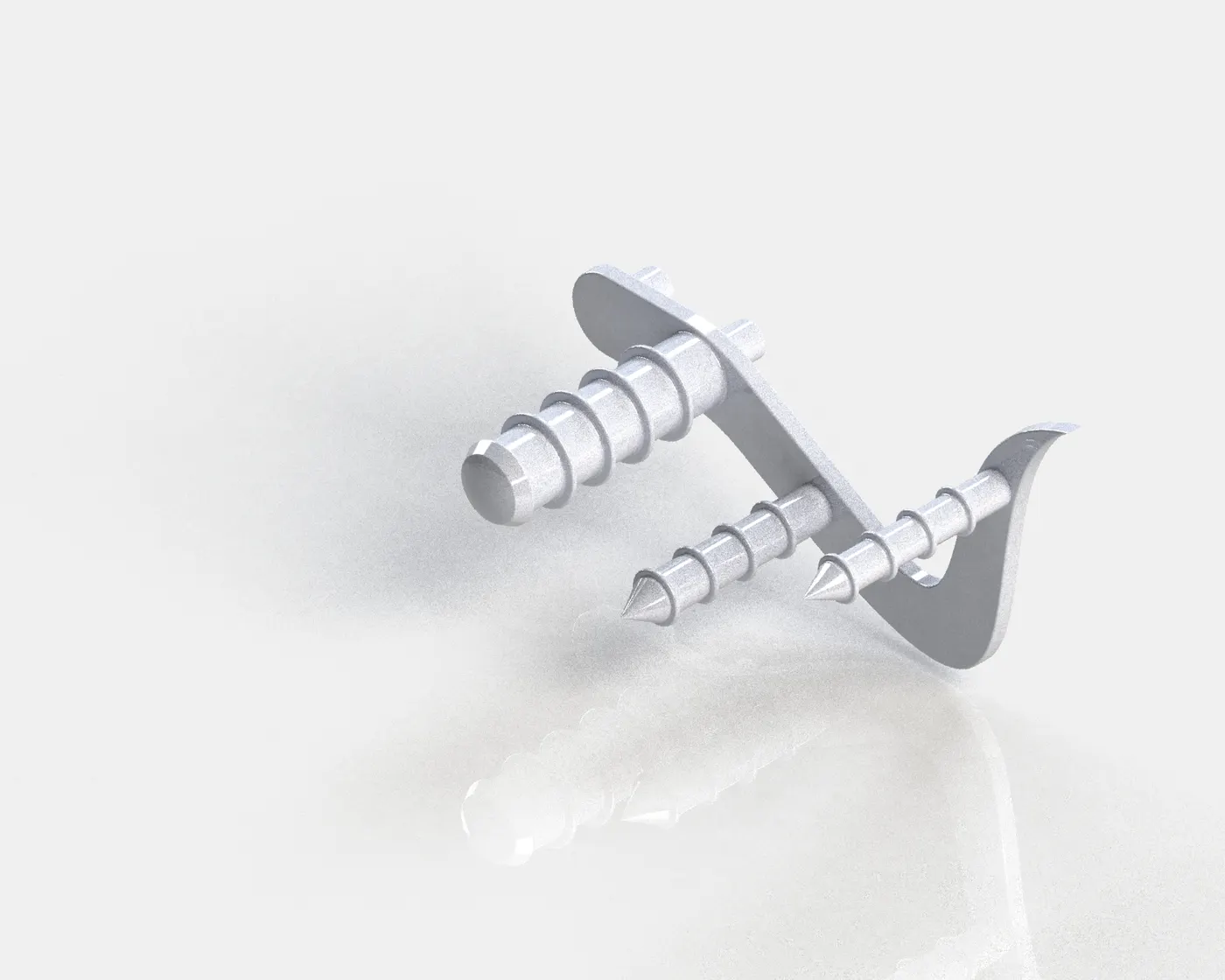
<!--[endif]-->Foot Pedal
<!--[endif]-->
Features used:
<!-- [if !supportLists]-->· <!--[endif]-->Extrude boss
<!-- [if !supportLists]-->· <!--[endif]-->Linear pattern
<!-- [if !supportLists]-->· <!--[endif]-->Fillet
<!-- [if !supportLists]-->· <!--[endif]-->Dome
<!-- [if !supportLists]-->· <!--[endif]-->Chamfer
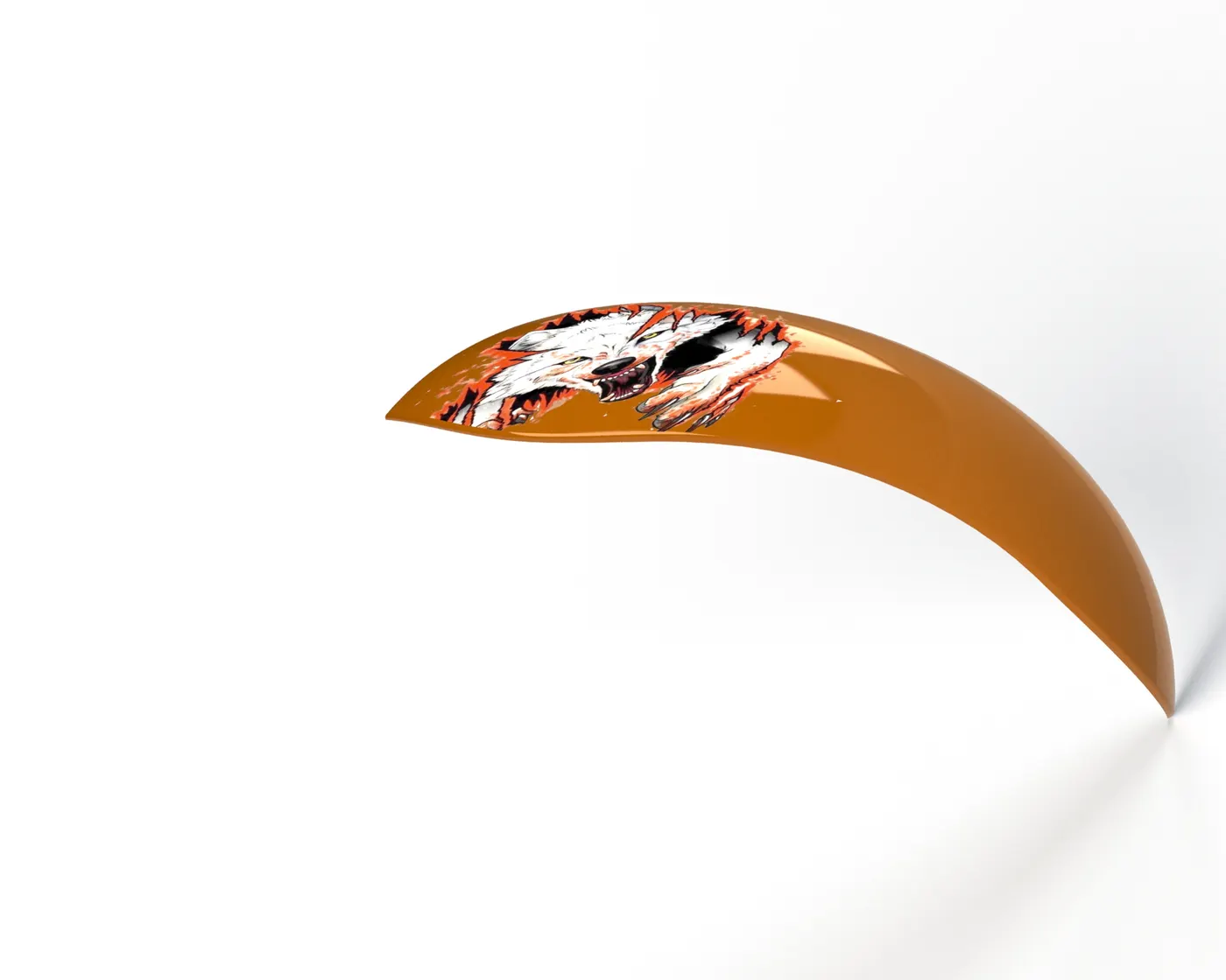
<!--[endif]-->Front Fender
<!--[endif]-->
Features used:
<!-- [if !supportLists]-->· <!--[endif]-->Offset entities
<!-- [if !supportLists]-->· <!--[endif]-->Trim entities
<!-- [if !supportLists]-->· <!--[endif]-->Revolve boss
<!-- [if !supportLists]-->· <!--[endif]-->Mirror
<!-- [if !supportLists]-->· <!--[endif]-->Split
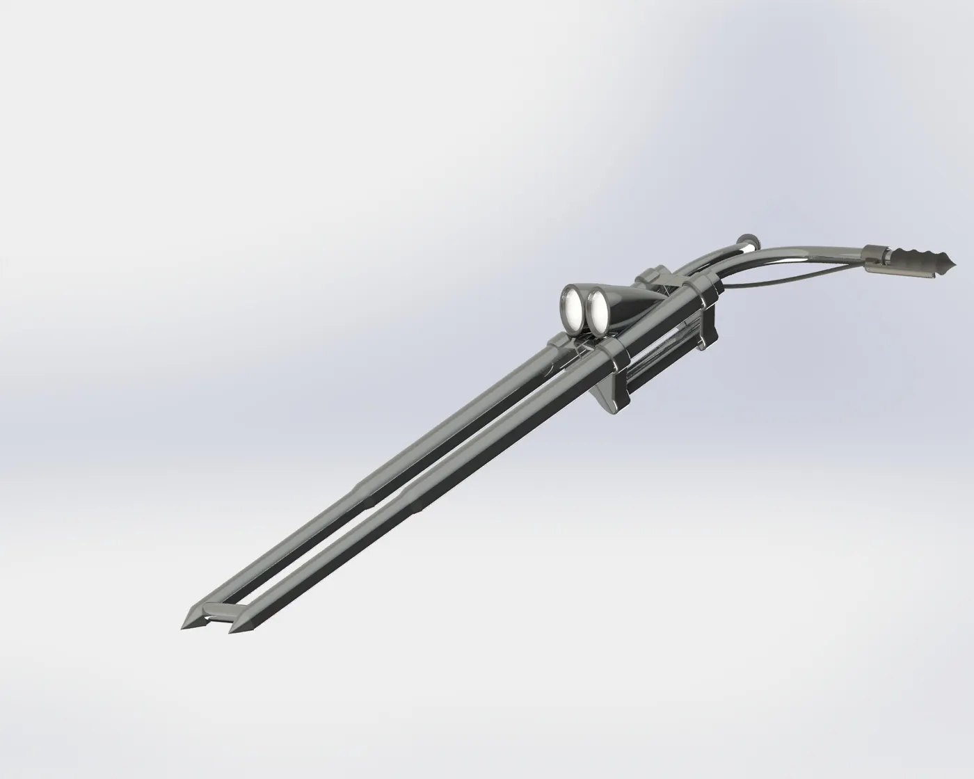
<!--[endif]-->Fork
<!--[endif]-->
Features used:
<!-- [if !supportLists]-->· <!--[endif]-->Extrude boss
<!-- [if !supportLists]-->· <!--[endif]-->Trim entities
<!-- [if !supportLists]-->· <!--[endif]-->Revolve boss
<!-- [if !supportLists]-->· <!--[endif]-->Split
<!-- [if !supportLists]-->· <!--[endif]-->Dome
<!-- [if !supportLists]-->· <!--[endif]-->Mirror
<!-- [if !supportLists]-->· <!--[endif]-->Combine
<!-- [if !supportLists]-->· <!--[endif]-->Projected curve
<!-- [if !supportLists]-->· <!--[endif]-->Swept boss
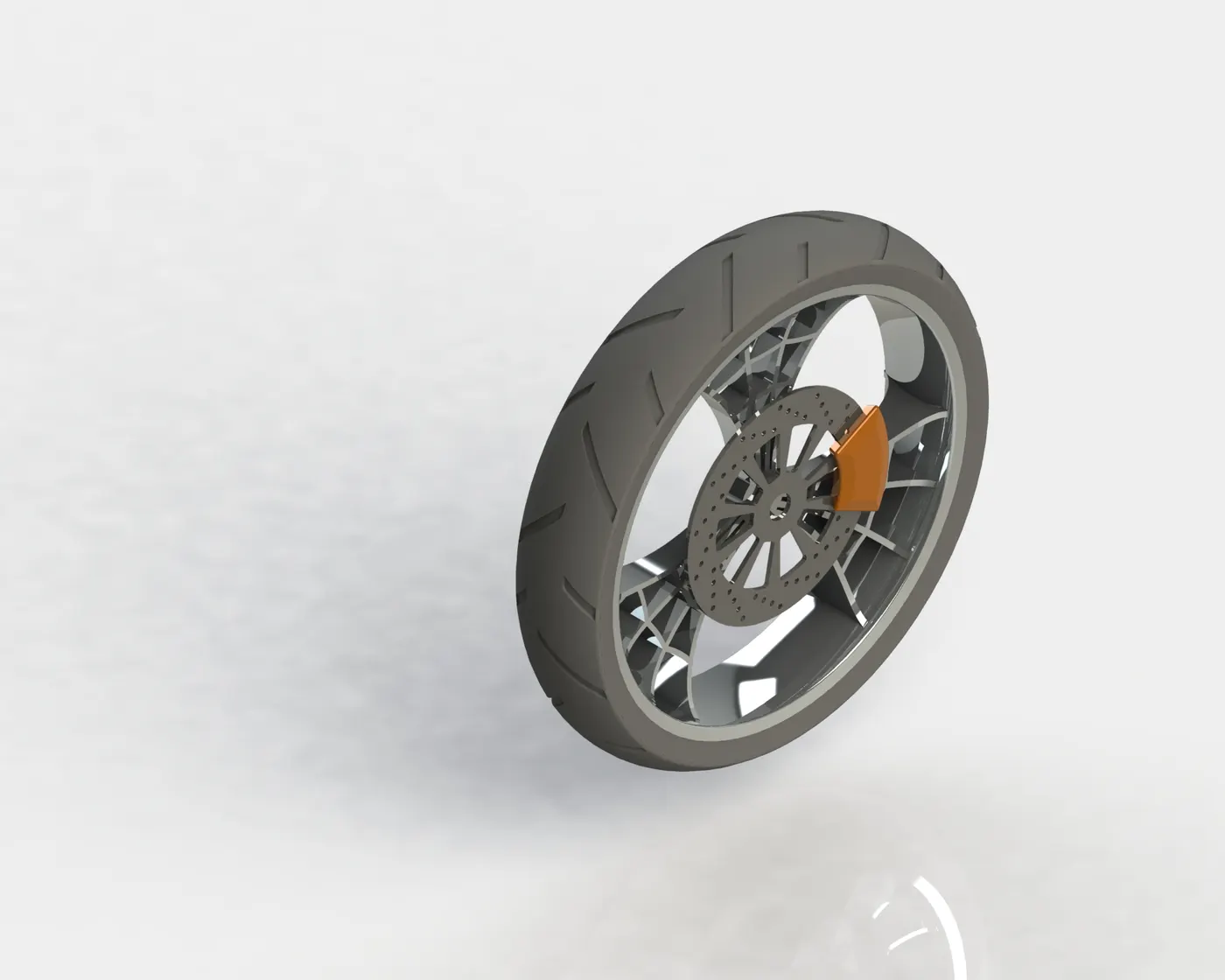
<!--[endif]-->Front Wheel
<!--[endif]-->
Features used:
<!-- [if !supportLists]-->· <!--[endif]-->Revolve boss
<!-- [if !supportLists]-->· <!--[endif]-->Trim entities
<!-- [if !supportLists]-->· <!--[endif]-->Boss Extrude
<!-- [if !supportLists]-->· <!--[endif]-->Revolve Cut
<!-- [if !supportLists]-->· <!--[endif]-->Linear Pattern
<!-- [if !supportLists]-->· <!--[endif]-->Chamfer
<!-- [if !supportLists]-->· <!--[endif]-->Cut Extrude
<!-- [if !supportLists]-->· <!--[endif]-->Circular Pattern
<!-- [if !supportLists]-->· <!--[endif]-->Fillet
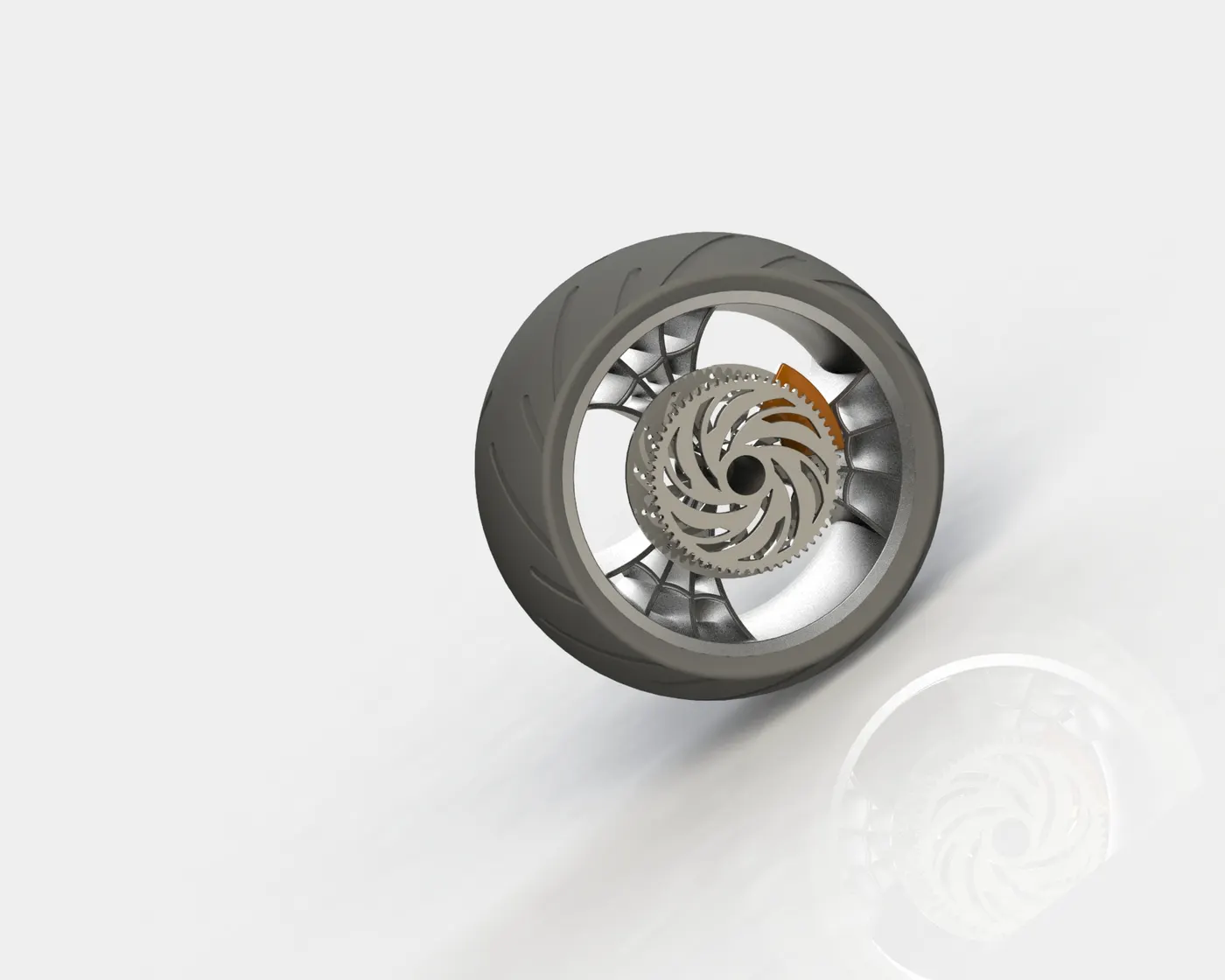
<!--[endif]-->Rear Wheel
<!--[endif]-->
Features used:
<!-- [if !supportLists]-->· <!--[endif]-->Revolve boss
<!-- [if !supportLists]-->· <!--[endif]-->Trim entities
<!-- [if !supportLists]-->· <!--[endif]-->Boss Extrude
<!-- [if !supportLists]-->· <!--[endif]-->Revolve Cut
<!-- [if !supportLists]-->· <!--[endif]-->Linear Pattern
<!-- [if !supportLists]-->· <!--[endif]-->Chamfer
<!-- [if !supportLists]-->· <!--[endif]-->Cut Extrude
<!-- [if !supportLists]-->· <!--[endif]-->Circular Pattern
<!-- [if !supportLists]-->· <!--[endif]-->Fillet
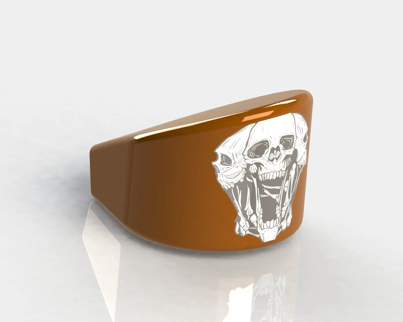
<!--[endif]-->Oil Tank
<!--[endif]-->
Features used:
<!-- [if !supportLists]-->· <!--[endif]-->Boss Extrude
<!-- [if !supportLists]-->· <!--[endif]-->Combine
<!-- [if !supportLists]-->· <!--[endif]-->Fillet
<!-- [if !supportLists]-->· <!--[endif]-->Shell
<!--[endif]-->Fuel Tank
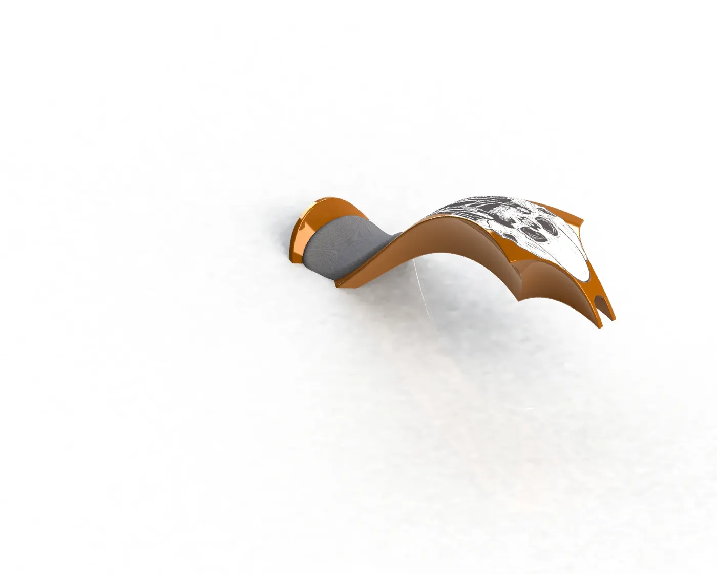
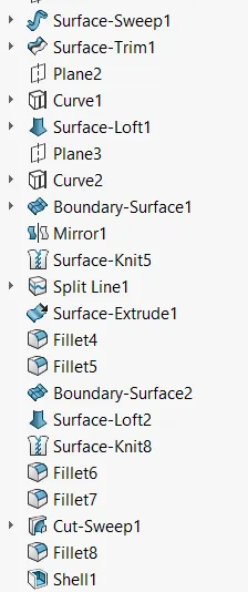
Features Used
Transmission Belt
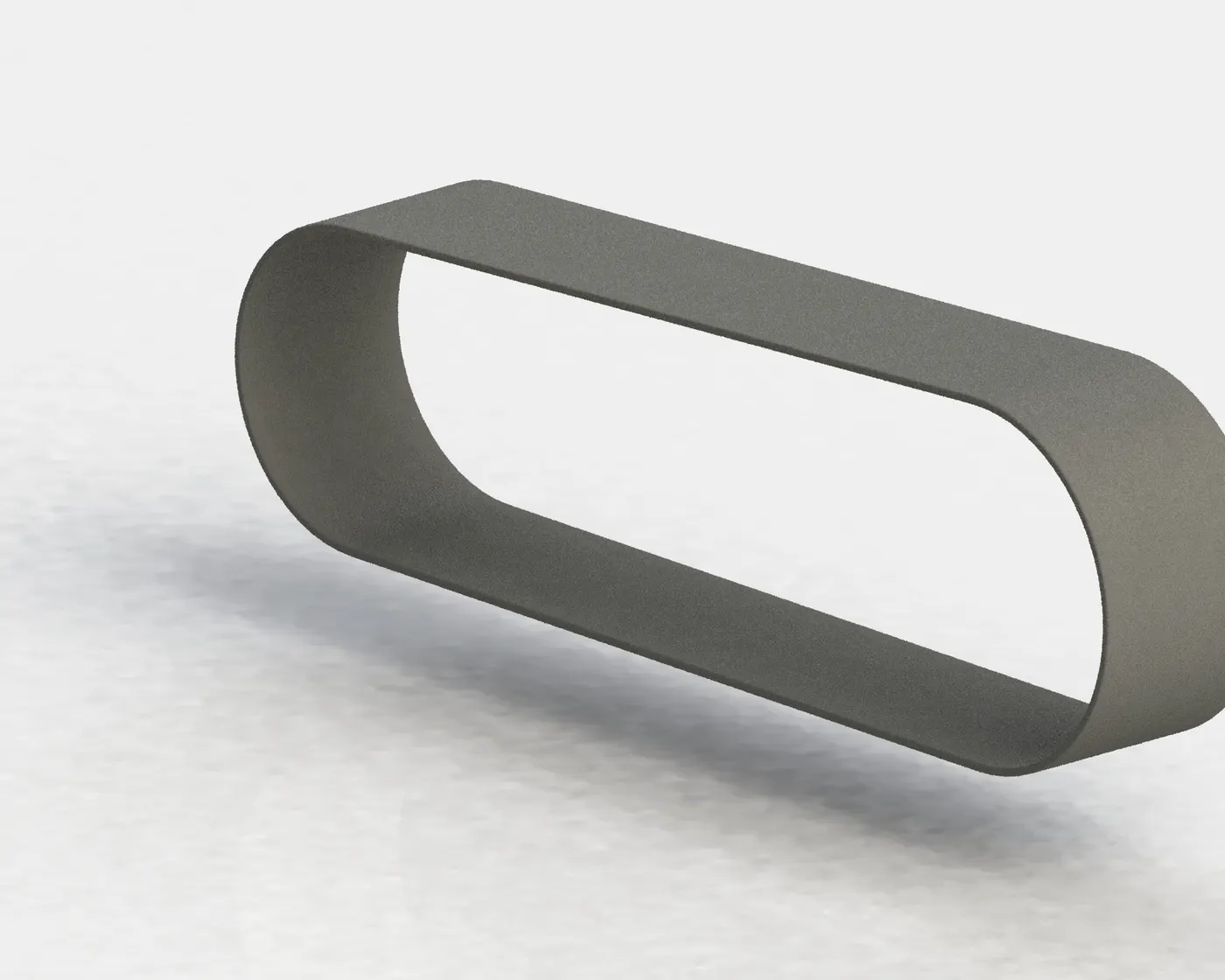
Features used:
· <!--[endif]-->Boss Extrude
<!-- [if !supportLists]-->· <!--[endif]-->Fillet
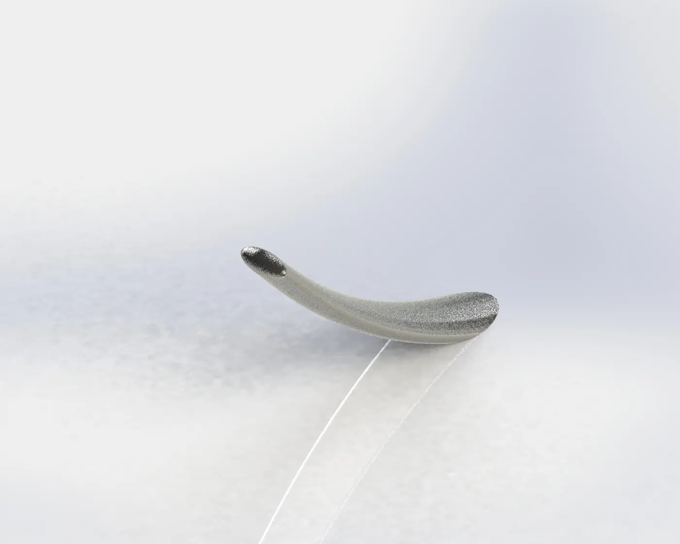
Side Stand
Features used:
· <!--[endif]-->Cut Extrude
· <!--[endif]-->Loft
<!-- [if !supportLists]-->· Split
<!-- [if !supportLists]-->· <!--[endif]-->Fillet
Assembly:
The first part taken into the assembly was the chassis, which provided the fixed base of the assembly. Later, different parts were imported into the assembly and constrained using suitable mates. Some post-assembly modifications and revisions were done in the exhaust of the engine and the chassis.
Rendered Images of Assembly
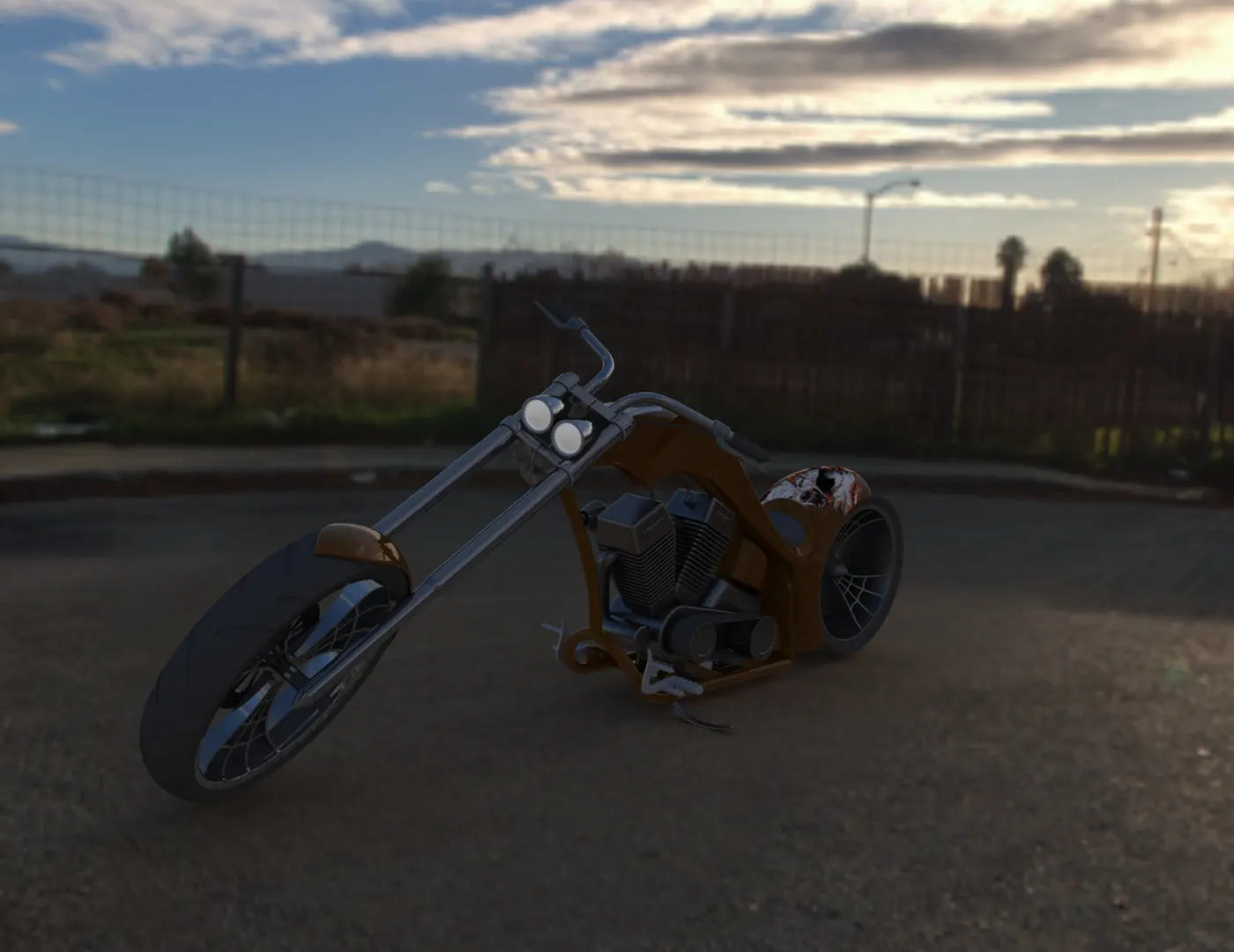
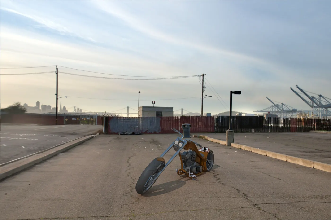
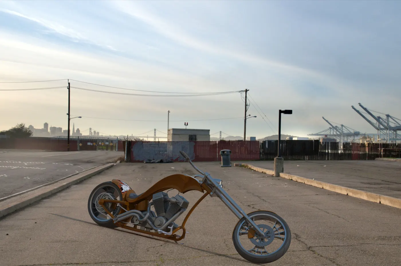
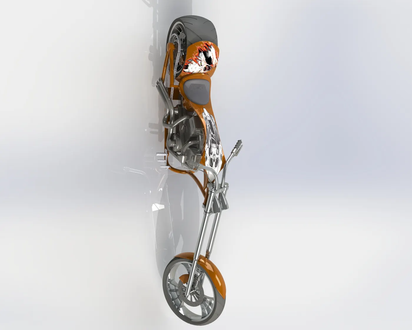
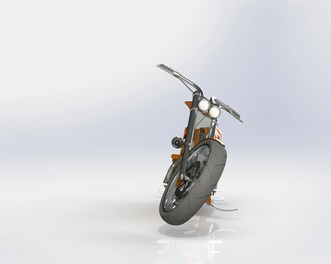
Photo View 360 Rendering
Photo view 360 is an internal add-in of Solidworks software that enables us to use rendering tools.
Tools used:
Scene
Decals
Cameras and Lights
Appearances
Scenes:
Two scenes used are: Urban 1 and Urban 2
Urban 1 and Urban 2 are embedded scenes with predefined backgrounds, Camera angles, and lights.
All the other scenes were customed to a color background and with custom floor offset according to the part.
Decals:
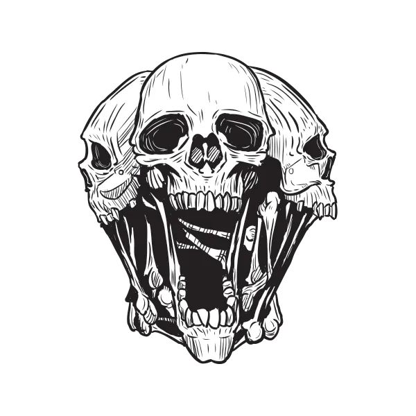
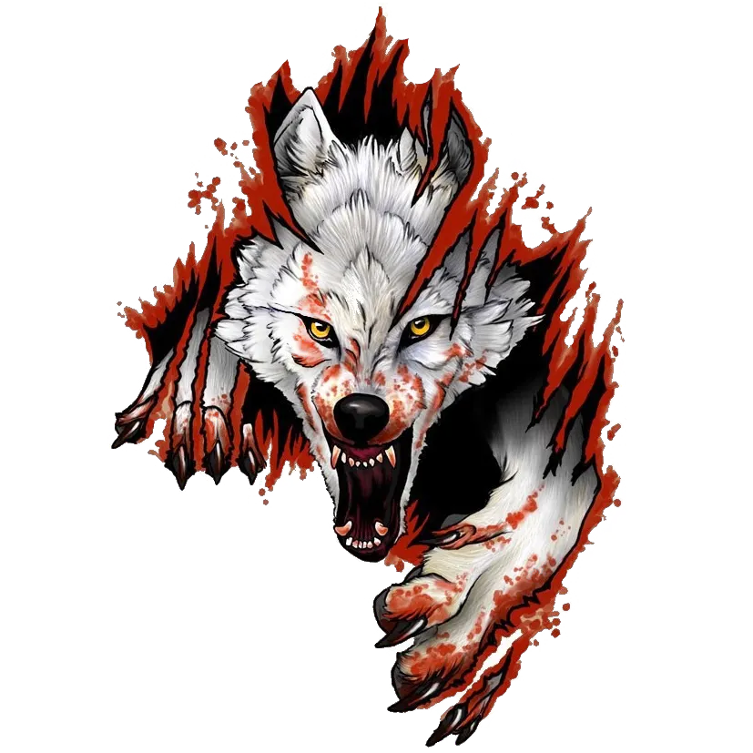
These are the graphics added to the tank and fenders. The decals used are:
Cameras and Lights
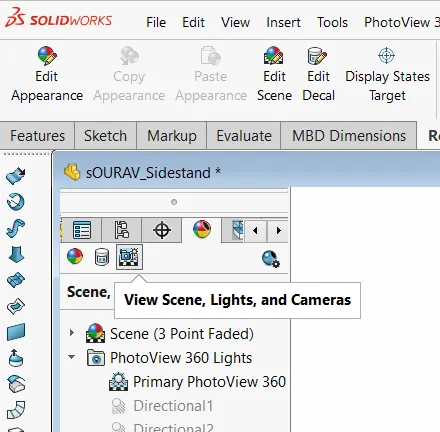
There are multiple ways to add or edit lights and cameras. One of them is to add them through the appearance manager.
Conclusion:
While Designing the American chopper, we got exposure to various part modeling tools and features with some surface modeling insights. We understood various mates used in assembly. The rendering was done using Photo View 360.
Note* The file size is limited to 20MB, so I couldn't upload the Zip file. I've uploaded individual parts here.