Designing, Modelling, Assembly and Photo realistic Rendering of Harley Davidson Motorcycle Engine in SOLIDWORKS
Designing, Modelling, Assembly and Photo realistic Rendering of Harley Davidson Motorcycle Engine.
Objective:
The main objective of this project is to ideate for Design and Assembly of a Harley Davidson Engine using Solid works 2020 & photo realistic Rendering of Assembly using photoview-360 and Solid works Visualize for understanding Mechanical Design process. Then Rendering is carried by adding proper cameras, lights and appearances.
Introduction:
In designing of any product first starts with an ideate and then convert these things into sketches by visualizing. Then these sketches are sent to designers for designing with proper dimensions by applying fundamentals of Engineering. These processes will be carried out until the design satisfies the proper requirements of customer needs and design parameters. Then these are modelled using Solid works by converting sketches into parts further these parts are joined together using Assembly for obtaining final product.
SOLIDWORKS is an 3D Modelling Computer-aided design software developed by Dassault systems. It uses a principle of 3d Parametric design and generates three kinds of interconnected files: the part, the assembly, and the drawing. It helps to perform easily Modelling by converting sketches(2D) to Parts(3D) easily using some Features. In Every part consists of sketches with appropriate dimensions using Required Geometries. Then by applying Features which are nothing but required shapes to be formed based on sketches. All these parts are to be separated in a new folder and then new assembly is selected to insert in this environment. In Assembly all these parts are assembled together by applying mates to two different parts on basis of planes and some relations like coincident, parallel and concentric. Then separate folder for mates is created to recognize easily relation between two parts.
An internal combustion engine (ICE) is a heat engine in which the combustion of a fuel occurs with an oxidizer (usually air) in a combustion chamber that is an integral part of the working fluid flow circuit. In an internal combustion engine, the expansion of the high-temperature and high-pressure gases produced by combustion applies direct force to some component of the engine. The force is applied typically to pistons, turbine blades, a rotor, or a nozzle. This force moves the component over a distance, transforming chemical energy into useful work. This replaced the external combustion engine for applications where weight or size of the engine is important.
In 2001, Harley made what was for it a radical move. A new engine called the “Revolution engine” was introduced, to be used in the upcoming motor cycles. The Revolution is still a V-twin, but it has a 60-degree V, is water-cooled, has 4 overhead camshafts and is high-revving (9,000 RPM redline). Beyond the engine, Harley motorcycles themselves have their own look and feel. Because of the big engines, Harleys tend to be big bikes. The biggest Harleys weigh close to a thousand pounds (453.6 kilograms).
Design process
1.Idea Generation:
The design process begins with understanding the customers and their needs.
2.Screening Ideas:
The purpose of screening ideas is to eliminate those ideas that do not appear to have high potential and
so avoid the costs incurred at subsequent stages.
3.Feasibility Study
Initial screening of the ideas is designed to stop the ideas, which are unsuitable for further considerations.
4.Preliminary Design:
Design engineers take general performance specifications and translate them in to technical specifications.
5.Testing:
Adjustments are made as needed before finalizing the design.
6.New Product Launch:
Marketing and production will work in a co-coordinated way during this phase.
Design Requirements
- Product should be designed innovatively.
- It should be designed by considering aesthetics.
- It should have good design in simple way.
- It must be also compact.
- It must be easy to repair at lower cost.
- It should be Renewable easily.
- The cost should be less for producing large in numbers.
- It must follow attention to details of product completely.
Design Intent
The intent of this project is to design Motor Bike Engine by using planes as reference for inserting components at required position. All components are designed and assembled by using required mates on basis of planes as their position.
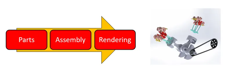
Design Methodology:
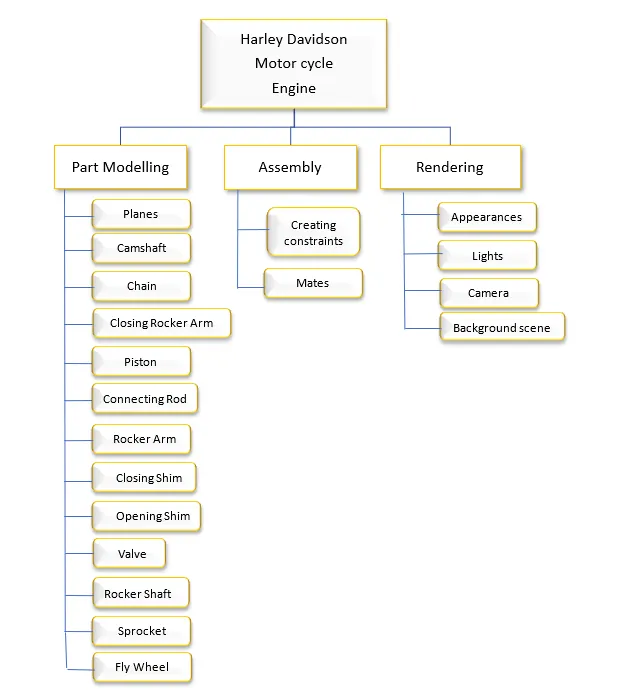
Working of Engine
A two-stroke engine is a type of internal combustion engine that completes a power cycle with two strokes of the piston during only one crankshaft revolution. This contrasts with a "four-stroke engine", which requires four strokes of the piston to complete a power cycle during two crankshaft revolutions. In a two-stroke engine, the end of the combustion stroke and the beginning of the compression stroke happen simultaneously, with the intake and exhaust functions occurring at the same time. Two-stroke engines often have a high power-to-weight ratio, power being available in a narrow range of rotational speeds called the "power band". Compared to four-stroke engines, two-stroke engines have fewer moving parts.
Overall, a two-stroke engine contains two processes:
- Compression stroke:The inlet port opens, the air-fuel mixture enters the chamber and the piston moves upwards compressing this mixture. A spark plug ignites the compressed fuel and begins the power stroke.
- Power stroke:The heated gas exerts high pressure on the piston, the piston moves downward (expansion), waste heat is exhausted.
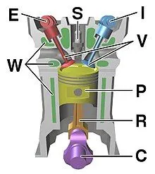
C – crankshaft
E – exhaust camshaft
I – inlet camshaft
P – piston
R – connecting rod
S – spark plug
V – valves. red: exhaust, blue: intake.
W – cooling water jacket
gray structure – engine block
Construction of a Harley Davidson Engine
As the name implies, the two-stroke engine only requires two piston movements (one cycle) to generate power. The engine is able to produce power after one cycle because the exhaust and intake of the gas occurs simultaneously. There is a valve for the intake stroke that opens and closes due to changing pressures. In addition, due to its frequent contact with moving components, the fuel is mixed with oil to add lubrication, allowing smoother strokes.
The thermal efficiency of these gasoline engines will vary depending on the model and design of the vehicle. However, in general, gasoline engines convert 20% of the fuel energy to mechanical energy in which only 15% will be used to move the wheels and rest is lost to friction and other mechanical elements.
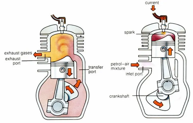
Piston – Piston transfers the expanding force of gases to the mechanical rotation of the crankshaft through a connecting rod.
Crankshaft – It converts the reciprocating motion to rotational motion.
Connecting Rod – It transfers motion from a piston to crankshaft and acts as a lever arm.
Flywheel – It is a mechanical device that is used to store energy.
Spark Plug – It delivers electric current to the combustion chamber and in turn ignites the air-fuel mixture leading to abrupt expansion of gases.
Counter Weight – Counterweight on the crankshaft is used to reduce the vibrations due to imbalances in the rotating assembly.
Inlet and Outlet Ports – These ports allow fresh air with fuel to enter and exit from the cylinder.
Two-Stroke Engine Cycle
Down Stroke
The piston moves from TDC (Top-Dead-Center) to BDC (Bottom-Dead-Center) letting the fresh air enter into the combustion chamber. The fresh air-fuel mixture gets into the combustion chamber through the crankcase. In this stroke, the crankshaft makes the rotation of 180 degress.
Up Stroke
The piston is pushed from BDC to TDC. As a result, the fuel-air mixture gets compressed and the spark plug ignites the mixture. The mixture expands, and the piston is pushed down. The inlet port is open during the upstroke. While the inlet port is opened, the mixture gets sucked inside the crankcase. When the mixture is pushed up into the combustion chamber during the previous upstroke, a partial vacuum is created as no mixture is left behind in the crankcase. This mixture is ready to go into the combustion chamber during downstroke but remains in the crankcase until the piston goes up till TDC. In this stroke, the crankshaft makes the rotation of 180 degrees.
Applications of Two-Stroke Engine
- Two-stroke engines are preferred when mechanical simplicity, lightweight, and high power-to-weight ratio are design priorities.
- They are lubricated by the traditional method of mixing oil into the fuel, they can be worked within any orientation as they do not have a reservoir dependent on gravity. This makes them desirable for their use in handheld tools such as chainsaws.
- Two-stroke engines are found in small scales propulsion applications such as motorcycles, Mopeds, and dirt bikes.
Otto Cycle
The pressure volume diagram (PV diagram) that models the changes the fuel-air mixture undergoes in pressure and volume in any gasoline engine is called the Otto cycle. The changes in these will create heat and use this heat to move the vehicle.
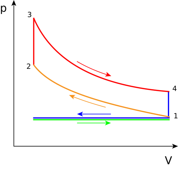
Process 1 to 2: During this phase, the inlet port opens, and the piston will be drawn up, so it can compress the fuel-air mixture that entered the chamber. The compression causes the mixture to increase slightly in pressure and temperature—however, no heat is exchanged. In terms of thermodynamics, this is referred to as an adiabatic process. When the cycle reaches point 2, it is when the fuel is met by the spark plug to be ignited.
Process 2 to 3: This is where combustion occurs due to the ignition of fuel by the spark plug. The combustion of the gas is complete at point 3, which results in a highly pressurized chamber that has lots of heat (thermal energy). In terms of thermodynamics, this is referred to as an isochoric process.
Process 3 to 4: The thermal energy in the chamber as a result of combustion is used to do work on the piston—which pushes the piston down—increasing the volume of the chamber. This is also known as the power stoke because it is when the thermal energy is turned into motion to power the machine or vehicle.
Purple line (Process 4 to 1): From process 4 to 1 all the waste heat is expelled from the engine chamber. As the heat leaves the gas, the molecules lose kinetic energy causing the decrease in pressure, However, there is no exhaust phase in a two-stroke engine, so the cycle begins (1 to 2) again by allowing a new mixture of fuel and air to be compressed.
Ideal cycle-green line: Referred to as the intake phase, a two-stroke engine does not go through this phase. This is because four stroke engines begin with the piston drawn up, so it must be drawn down to intake the fuel-air mixture. However, a two-stroke engine can proceed with intaking the fuel-air mixture right away as seen in Process 1 to 2.
Harley Davidson Engine:
In a two-cylinder, horizontally opposed engine, the pistons are timed so that one fires on one revolution of the crankshaft and the other fires on the next revolution -- so one of the two pistons fires on every revolution of the crankshaft. This seems logical and gives the engine a balanced feeling. To create this type of engine, the crankshaft has two separate pins for the connecting rods from the pistons. The pins are 180 degrees apart from one another.
A Harley engine has two pistons. The difference in the Harley engine is that the crankshaft has only one pin, and both piston rods connect to it. This design, combined with the V arrangement of the cylinders, means that the pistons cannot fire at even intervals. Instead of one piston firing every 360 degrees, a Harley engine goes like this:
- A piston fires.
- The next piston fires at 315 degrees.
- There is a 405-degree gap.
- A piston fires.
- The next piston fires at 315 degrees.
- There is a 405-degree gap.
Here are some of the distinguishing characteristics of the engine:
- In this two-cylinder V-twin design with a 45-degree angle between the cylinders has used.
- The engines are air-cooled.
- The engines have overhead valves that are activated by camshafts in the crankcase.
- Oil comes from a dry sump lubrication system
- Harley engines have a long stroke. This means that the engines are low-revving and have lots of torque. It is typically in the 5,000 RPM range.
- Harley engines have a single-pin crankshaft, giving these engines a unique sound.
List of Parts used in Assembly
- Flywheel
- Connecting rod
- Piston
- Camshaft
- Closing Rocker Arm
- Rocker Shaft
- Rocker Arm
- Valve
- Opening Shim
- Closing Shim
- Sprocket
- Chain
Planes
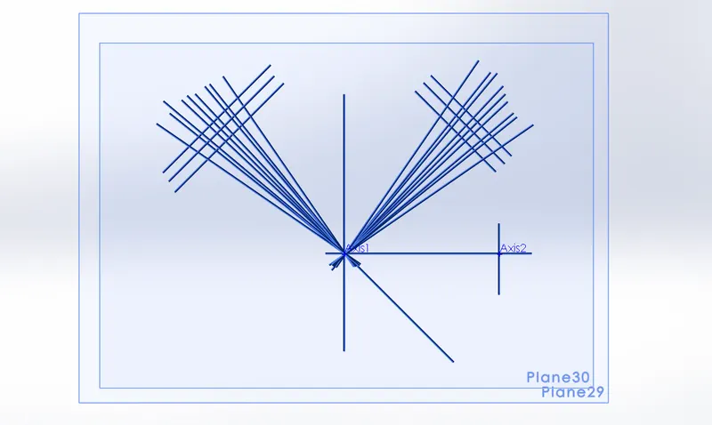
Initially all the planes are arranged in a way on basis of inserting parts at certain positions. Then these planes are extended that intersects each other for placing part by taking their axis as a reference for applying coincident relation with all required planes. In this way all parts are constrained in a particular position for getting proper assembly as a result.
Description about Parts
Camshaft
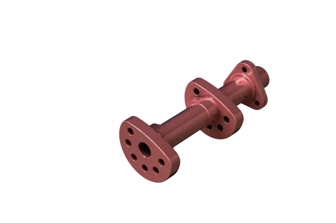
A camshaft is a rotating object, usually made of metal that contains pointed cams, which converts rotational motion to reciprocal motion. Camshafts are used in internal combustion engines mechanically controlled ignition systems and early electric motor speed controllers. Camshafts in automobiles are made from steel or cast iron, and are a key factor in determining the RPM range of an engine's power band.
Commands used in Sketch
- Line
- Circle
- Trim
- Polygon
- Fillet
Commands used in Features
- Extrude Boss
- Extrude cut
- Circular pattern
- Mirror
- Fillet
Steps for modelling Camshaft:
- Required plane is selected for sketching two circles that are coincident to each other by appropriate dimensions. Edges are removed by using trim command to Extrude these sketches.
- These Extrude surface is selected for sketching circle and Extrude cut is applied through it. Then these features selected for applying circular to increase the number of features.
- On this surface two circles which are coincident to each other are drawn and removed unwanted sketches for applying extrude boss. On this surface circle is drawn and applied Extrude Boss with required dimensions.
- One of the faces is selected and whole part is mirrored on basic of this face. Polygon is drawn on this surface and edges are removed by applying fillets.
- These sketches are selected for applying extrude boss. On one of the edges circles is drawn for applying Extrude cut though all. Required fillets are applied to all edges of part.
Chain
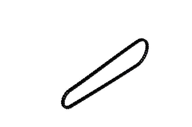
It is a roller chain that provides transfer of power from engine to wheels. The power driven by roller chain are known as drive chain or transmission chain. It causes the gear that drives a wheel to rotate more than one revolution. These chains are made of multiple pairs of steel both outer and inner plates and pins are inserted between them. The roller separates each pair of inner plates. Mostly chains are made of materials like plain carbon or alloy steel, but some are nickel plate to prevent from rust.
Commands used in sketch
- Circle
- Lines
- Properties
- Arc
- Trim
- Properties
Commands used in Features
- Boss Extrude
- Blocks
- Linear pattern
- Fillet
- Mirror
- Appearance
Steps for Modelling Chain:
- The required plane is selected then sketch is drawn with appropriate geometries like lines and Arcs with required dimensions.
- Two chain plates are drawn by using blocks command make them as separate in new folder. Then open the sketch and browse two plates then place them at required positions by using properties like concentric and coincident.
- Then use linear pattern select the pattern curve as required line with appropriate number of chain plates. Add fillet to edges of pins to remove sharp edges
- Select other geometry pattern and follow same as above steps. Then separate the pins into one folder and chain plates into other folder for easy selection.
- Then select chain plates and mirror it towards front plane to form chain plates at other side. By using Appearance add required material to chain.
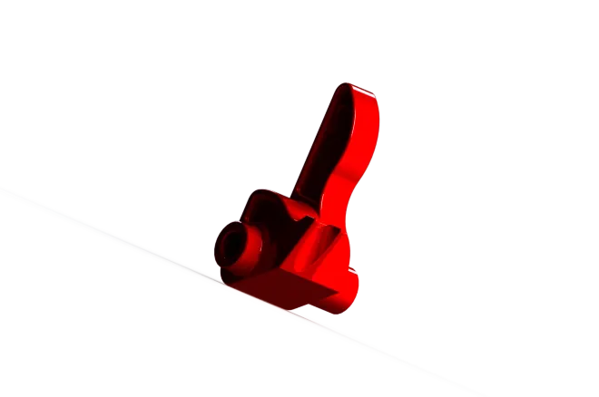
Closing Rocker Arm
Rocker arm controlled by camshaft through push rod, there is lobes on camshaft designed as per the timing of opening and closing of inlet and exhaust valves, valves open as per the timing which is decides by cam sensor which mounted just above the camshaft teeth.
Commands used in Sketch
- Line
- Arc
- Circle
- Slot
Commands used in Features
- Extrude Boss
- Convert Entities
- Offset
- Extrude cut
Steps for modelling Closing Rocker Arm:
- Required plane is selected for sketching using some geometric entities like line, arc and circle with appropriate dimensions for constraining sketch.
- These sketches is selected for applying Extrude Boss. Edges are selected for applying Convert Entities and Offset is selected for sketching the required sketches with dimensions.
- Surface of Extrude Boss is selected for sketching circle. These sketches are selected for applying Extrude Boss in both directions. Then earlier sketch is selected for applying Extrude Boss.
- Fillets are applied to all required edges of part. The required face is selected for sketching circle and applied Extrude cut to these sketches.
- Slot is drawn on one of the edges with required dimensions for applying Extrude cut to whole part. Fillets are applied to whole part at required edges.
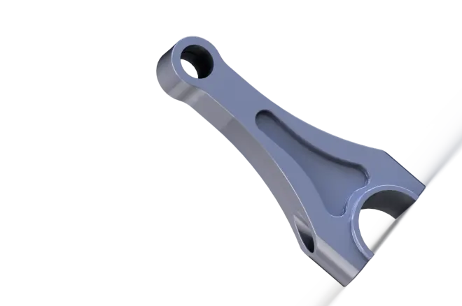
Connecting rod
The connecting rod is generally abbreviated to con-rod. The crankshaft con-rod mechanism transforms reciprocatively motion to rotational motion. The con-rod connects the piston to the crankshaft to transfer combustion pressure to the crankpin.
Commands used in Sketch
- Line
- Circle
- Rectangle
- Arc
- Trim
- Slot
Commands used in Features
- Extrude Boss
- Fillet
- Extrude cut
- Draft
Steps for modelling Connecting rod:
- At first rectangle is drawn on required plane and circle is drawn on coincident to this rectangle then unwanted sketches are removed.
- Then whole sketch is selected for applying Extrude boss. Draft is applied to all edges. Circle is drawn on its surface for applying extrude boss. Three slots are drawn that coincident to each other by removing unwanted sketches.
- Then Extrude cut is applied to these sketches. At bottom sketches using arcs are drawn and applied extrude cut through all the part. Fillets are applied to all required edges.
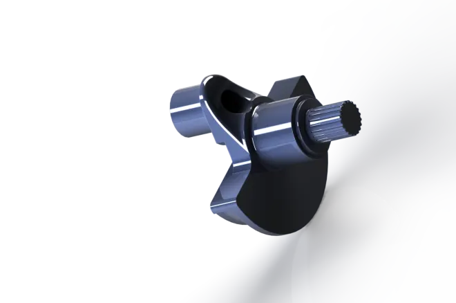
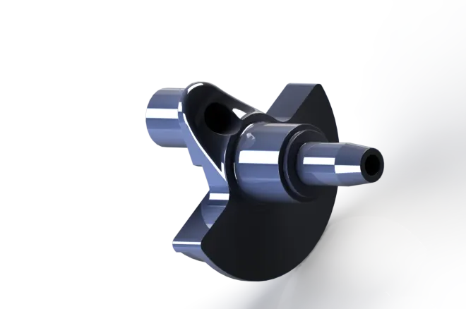
Flywheel
Flywheel, heavy wheel attached to a rotating shaft to smooth out delivery of power from a motor to a machine. The inertia of the flywheel opposes and moderates fluctuations in the speed of the engine and stores the excess energy for intermittent use. To oppose speed fluctuations effectively, a flywheel is given a high rotational inertia; most of its weight is well out from the axis
Flywheel(Spline shaft):
Flywheel(Tapered shaft):
Commands used in Sketch
- Lines
- Circle
- Arc
Commands used in Features
- Extrude Boss
- Revolved Boss
- Revolved cut
- Extrude cut
- Circular pattern
Steps for modelling Flywheel:
- At first required plane is selected and sketches are drawn by using lines and Circles with required dimensions. Then on basis of this part sketches are drawn on side for applying Revolve Boss.
- On this part sketches by using arcs with proper dimensions are drawn by applying relations for constraining sketch. Then Revolved cut is applied for this sketch. Revolved model is selected and drawn circle on this face for applying Extrude cut.
- Right plane is selected for sketching by using lines at bottom edge for applying Revolve cut. Fillets are applied at required edges.
- This file is saved and on taper shaft rectangle is drawn for applying Extrude cut. sketch is drawn on this surface for applying revolved cut.
- These features are selected and applied along circular pattern for creating a greater number of entities around this surface. Fillets are applied to all edges.
Shim
The bucket rests on top of the valve, over the valve stem and spring, and the cam acts directly against the shim. Generally, when a shim-over-bucket design is employed, the shims can be removed and replaced without disturbing the cams.
Closing Shim
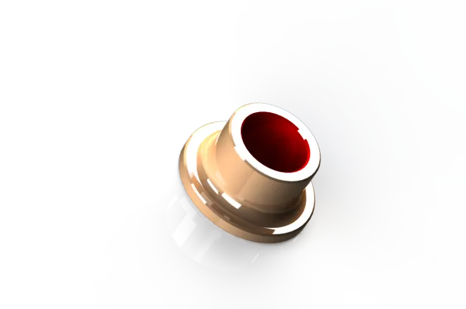
Commands used in Sketch
- Circle
- Convert Entities
- Offset
Commands used in Features
- Extrude Boss
- Chamfer
- Fillet
Steps for modelling Closing Shim:
- At first Top plane is selected for sketching circle. Then these sketches is selected for applying Extrude Boss.
- These surfaces is selected for sketching by using Convert Entities earlier sketch is selected and by using offset circle is drawn.
- Then these sketches are selected for applying Extrude Boss. Chamfer is applied to the one of the edges. Required fillets are applied to all edges.
Opening shim
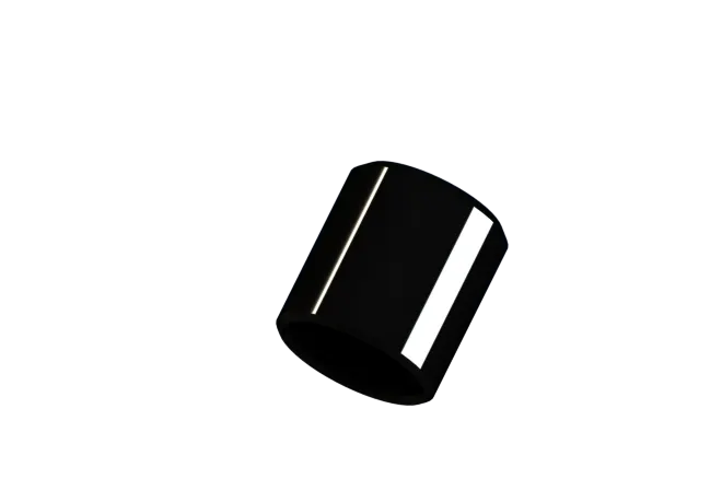
Commands used in Sketch
- Circle
- Line
Commands used in Features
- Extrude Boss
- Fillets
- Extrude Cut
Steps for modelling Opening Shim:
- At first required plane is selected for applying sketches using circle with proper dimensions.
- On this Extrude surface sketch is drawn by using circle and these are selected for applying Extrude cut.
- Fillets are applied to required edges.
Valve
Engine valves are mechanical components used in internal combustion engines to allow or restrict the flow of fluid or gas to and from the combustion chambers or cylinders during engine operation.
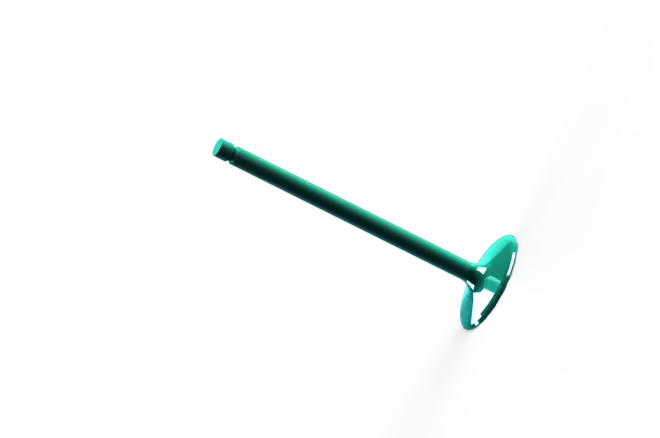
Commands used in Sketch
- Lines
- Circle
Commands used in Features
- Revolved Boss
- Fillet
Steps for modelling Valve:
- Required plane is selected for sketching lines with required dimensions by applying relations for constraining geometry. These sketches are selected for applying revolved boss.
- Fillets are applied to required edges.
Rocker Arm
A rocker arm is an oscillating lever that conveys radial movement from the cam lobe into linear movement at the poppet valve to open it. One end is raised and lowered by a rotating lobe of the camshaft while the other end acts on the valve stem.
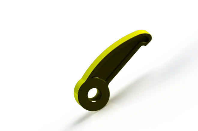
Commands used in Sketch
- Circle
- Line
- Arc
- Convert Entities
- Offset
Commands used in Features
- Extrude Boss
- Extrude cut
- Fillets
Steps for modelling Rocker Arm:
- At first required plane is selected for sketching using required Entities like line, circle and arc by applying proper dimensions for constraining sketch.
- These Extrude Boss is selected for sketching by using convert entities earlier sketches and these sketches are selected for offset. Extrude cut is done by selecting these sketches.
- Circle is drawn on one of the faces for applying Extrude cut. Fillets are applied to all required edges. For applying hole one of the edges is selected for sketching and Extrude cut is applied.
Sprocket
A sprocket, sprocket-wheel or chainwheel is a profiled wheel with teeth, or cogs, that mesh with a chain, track or other perforated or indented material. The name 'sprocket' applies generally to any wheel upon which radial projections engage a chain passing over it. The most common form of sprocket may be found in the bicycle, in which the pedal shaft carries a large sprocket-wheel, which drives a chain, which, in turn, drives a small sprocket on the axle of the rear wheel.
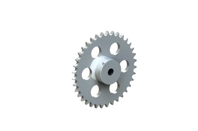
Commands used in Sketch
- Circle
- Line
Commands used in Features
- Extrude boss
- Extrude cut
- Fillet
Steps for modelling Sprocket:
- At first required plane is selected for sketching two circles which are Concentric to each other.
- Extrude boss is applied to these sketches and these surfaces is selected for sketching circle at its center.
- These circles is selected for applying Extrude cut through all. Required number of teeth are provided. Fillets are added to required edges.
Piston
A piston is a component of reciprocating engines, reciprocating pumps, gas compressors, hydraulic cylinders and pneumatic cylinders, among other similar mechanisms. It is the moving component that is contained by a cylinder and made gas-tight by piston rings. In an engine, its purpose is to transfer force from expanding gas in the cylinder to the crankshaft via a piston rod or connecting rod. In some engines, the piston also acts as a valve by covering and uncovering ports in the cylinder.
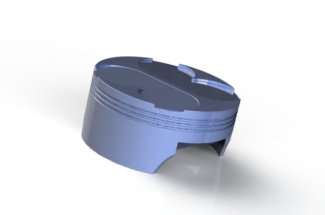
Commands used in Sketch
- Circle
- Rectangle
- Trim
Commands used in Features
- Extrude Boss
- Revolved cut
- Linear pattern
- Shell
- Rib
- Fillets
Steps for modelling Piston:
- At first top plane is selected and circle is drawn for applying Extrude. Then sketch is drawn on this surface for applying Revolved cut. These sketches are selected for linear pattern around Extrude boss for increasing number of features.
- Shell is created at bottom surface for removing inner material. Then bottom surface is selected for sketching rectangle with appropriate dimensions. These sketches are selected for applying Extrude boss. Surface of these Extrude is selected for sketching lines on both surfaces. Then Rib is applied to all this sketch.
- One of the surfaces is selected for sketching circle. Then Extrude cut is applied to extend the other surface. Then top plane is selected for sketching circles along all the edges that covers whole surface of piston.
- These circles are intersected and by using trim internal sketches are removed. These sketches are selected for applying Extrude cut with lower dimension. Fillets are applied to all the required edges.
Rocker Shaft
It is a shaft that gives support for constraining Rocker Arm. Both the Rocker arm and closing Rocker arm mounted on this shaft opposite to each other at edges of shaft
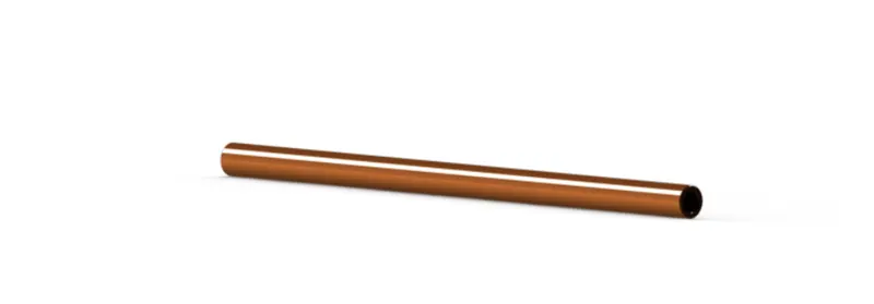
Commands used in sketch
- Circle
- Line
Commands used in Features
- Extrude boss
- Fillet
Steps for modelling Rocker shaft:
- At first required plane is selected for sketching the circles with required dimensions.
- Two circles which are Concentric to each other are drawn for applying Extrude boss with large dimensions for getting shaft.
Assembly
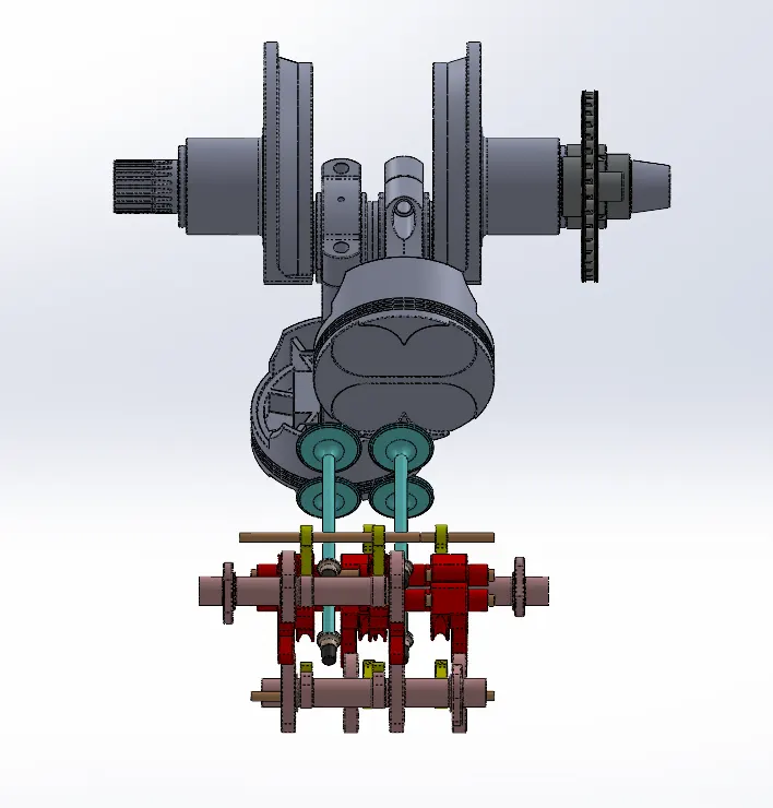
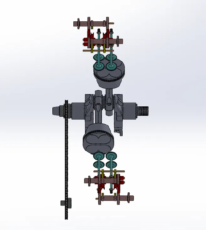
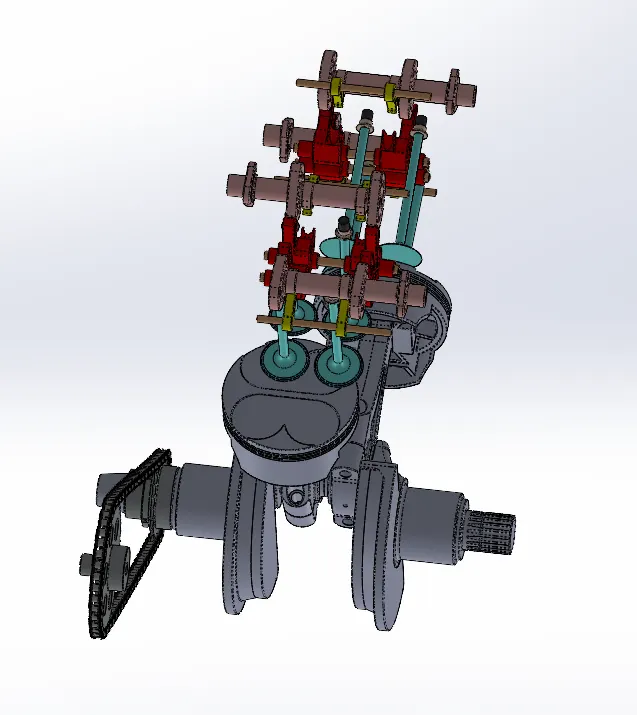
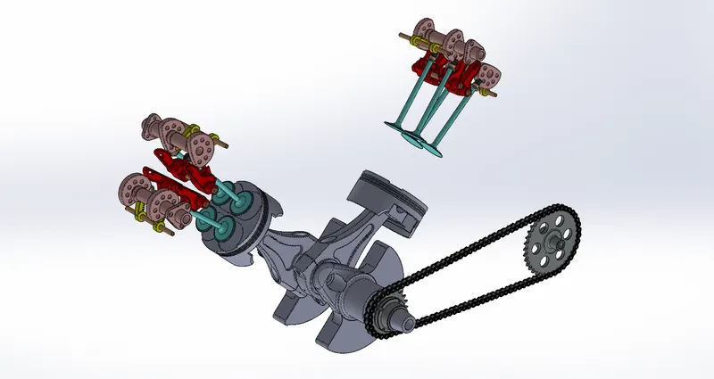
At first required component is inserted then on basis of the axis of these component mates is applied with required plane. In same way all the required components are inserted and applied different mates for constraining these parts. And for some component’s mates are applied on reference to other parts. By using planes as reference mostly all components are placed. At some parts Cam Tangent mate is applied to follow exactly circular surface of the part.
Standard views of Engine:
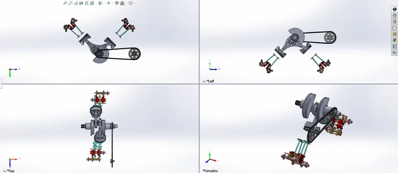
Front view:
Top view:
Side view:
Isometric view:
Camera View:
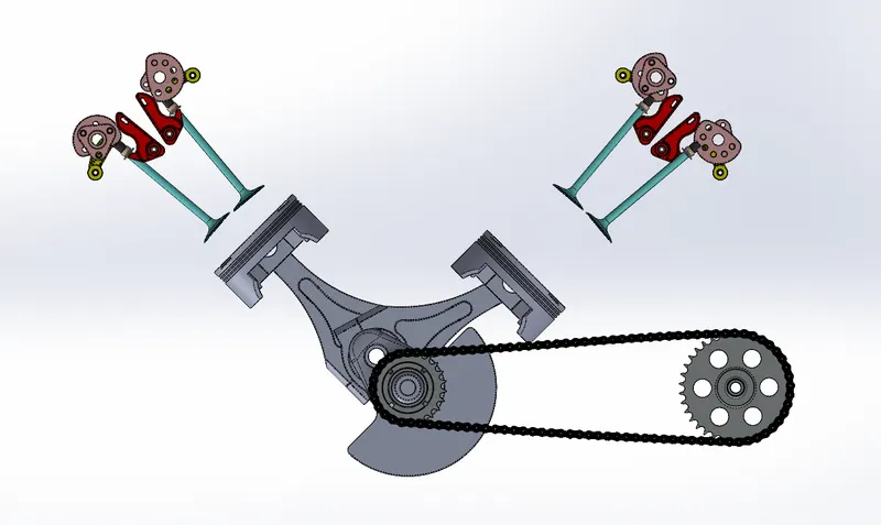
Rendering
Rendering or image synthesis is the process of generating a photorealistic or non-photorealistic image from a 2D or 3D model by means of a computer program. The term "rendering" is also used to describe the process of calculating effects in a video editing program to produce the final video output.
Rendering of Harley Davidson Engine is done by using PhotoView-360 and SOLIDWORKS Visualization.
PhotoView-360
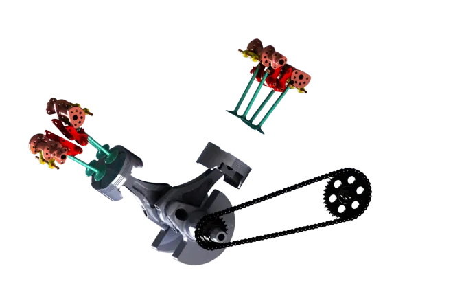
PhotoView-360 is a visualization and rendering solution included with SOLIDWORKS Professional and SOLIDWORKS Premium. It Provides a highly interactive environment for viewing designs as well as for creating photo-realistic renderings that can be used to showcase our designs.
Lighting:
PhotoView-360 proof sheets let you select lighting settings by viewing the effects of a range of settings in a series of proof sheets. Each image represents a different setting for our primary PhotoView-360 lighting. Rendering brightness, background brightness, and scene reflectivity are controlled by the PhotoView-360 Scene Illumination Proof Sheet, a dialog box that lets you quickly see a wide range of variations of these parameters.
Scenes:
By adding PhotoView-360 in, scenes it provides a realistic light source, including illumination and reflections, requiring less manipulation of lighting. The objects and lights in a scene can form reflections on the model and can cast shadows on the floor.
Decals:
A decal is a 2D image applied to a model. These decals can be used to apply warning or instruction labels to models. These can also be used to create model details that can effectively represent with an image instead of with the model geometry, such as a car grill or a picture frame.
Options:
The PhotoView-360 Options Property Manager controls settings for PhotoView-360, including output image size and render quality
Output:
Then rendered images from photoview-360 are monitored on screen and can be saved to our files.
Workflow
- With a model open, click Tools > Add-In and add in Photo-View 360.
- Start a preview in the graphics area or open the Preview window to see how changes for making the model that affects the rendering.
- Edit appearances, the scene, and decals.
- Edit lights. By default, lighting is off in Photo-View. With lights off, you can use the realistic lighting provided by scenes, which is usually enough for rendering. You typically need additional lighting in Photo-View to illuminate occluded spaces in the model.
- Edit Photo-View Options.
- When we are ready, perform a final render either now (Photo-View > Final Render) or later (Photo-View > Schedule Render).
If you have not added a camera or turned on perspective view, which provide more realistic, higher quality renderings, a dialog box appears. It allows us to turn on a camera or perspective view from the dialog box or continue without them.
- Providing detailed adjustments in the Final Render Window.
SolidWorks Visualization
SOLIDWORKS Visualize allows us to leverage our 3D CAD data to create photo-quality content in the fastest and easiest way that we can from images to animations, interactive web content, and immersive Virtual Reality that can brings our products to life. SOLIDWORKS Visualize is the “camera” for our CAD data.
SOLIDWORKS Visualize Boost is a service that allows us to distribute rendering from a computer running SOLIDWORKS Visualize Professional to one or more computers on a network. You can perform other tasks on your machine while the rendering is being carried out, and the final rendered images are available sooner. Images can be rendered on a single machine, or on a cluster of several machines running Visualize Boost.
SOLIDWORKS Visualize products (formerly known as Bunk speed) provide a suite of standalone software tools that combine industry-leading rendering capabilities with design-oriented features and workflows for designers, engineers, marketers, and other content creators. It is possible to import SOLIDWORKS, and other CAD formats to create compelling, highly realistic content.
Rendered Images
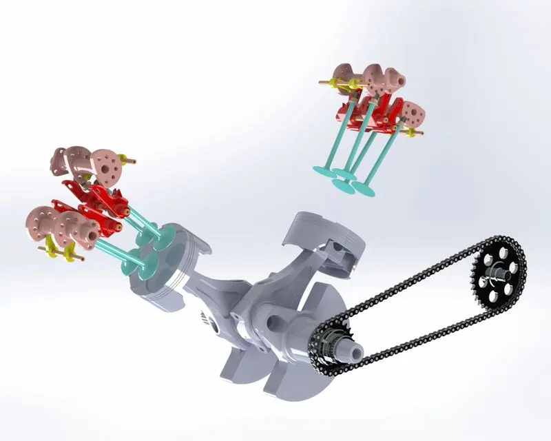
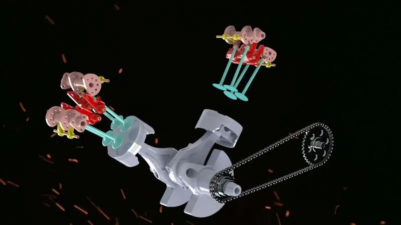
To render output to a Visualize Boost cluster:
- In SOLIDWORKS Visualize Professional, open a model and click Tools > Render, or in the main toolbar, click Output Tools
- In the Output Tools dialog box, under the Render Settings area, click Power Boost. The Cluster name displays.
- Set the Render Mode. We can set a time limit or select Quality and enter a number of Passes. The default of 500 passes is adequate for most render jobs.
- To start rendering at a later time, select Send to Queue. The job is sent to the SOLIDWORKS Visualize Queue and does not complete until we click Start Queue in the Queue Client.
- If we are ready to render, select Show Progress to monitor the rendering process. Then click Start Render.
We can click Pause, Save Now, or Cancel to stop the rendering.
Conclusion:
Thus, the designing and assembly of Harley Davidson Motorcycle Engine using SOLIDWORKS & photorealistic rendering using Photo-view 360 and SOLIDWORKS visualization has been done.