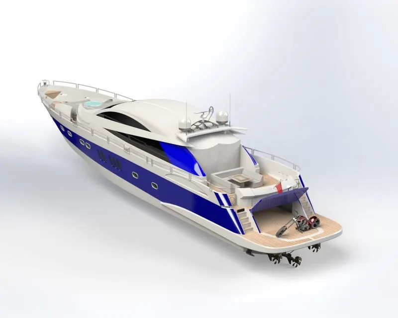
Surface Modelling of American Predator Yacht
Design, Assembly and Photo-Realistic Rendering of an American Predator Yacht
Objective:
The main objective of this project is to ideate for Design and Assembly of a Predator Yacht using Solid works 2020 and photo realistic Rendering of yacht using photoview-360 and Solid works Visualize for understanding Mechanical Design process. Then Rendering is carried by adding proper decals, cameras, lights and appearances.
Introduction:
In designing of any product first starts with an ideate and then convert these things into sketches by visualizing. Then these sketches are sent to designers for designing with proper dimensions by applying fundamentals of Engineering. These processes will be carried out until the design satisfies the proper requirements of customer needs and design parameters. Then these are modelled using Solid works by converting sketches into parts further these parts are joined together using Assembly for obtaining final product.
Solidworks is an 3D Modelling Computer-aided design software developed by Dassault systems. It uses an principle of 3d Parametric design and generates three kinds of interconnected files: the part, the assembly, and the drawing. It helps to perform easily Modelling by converting sketches(2D) to Parts(3D) easily using some Features. In Every part consists of sketches with appropriate dimensions using Required Geometries. Then by applying Features which are nothing but required shapes to be formed based on sketches. All these parts are to be separated in a new folder and then new assembly is selected to insert in this environment. In Assembly all these parts are assembled together by applying mates to two different parts on basis of planes and some relations like coincident, parallel and concentric. Then separate folder for mates is created to recognize easily relation between two parts.
American Predator Yacht is a superyacht built in 2008 at the Dutch shipyard Royal De Vries Aalsmeer. The interior design of the Predator was done by Bannenberg Designs and the exterior by De Voogt Naval Architects. The main engines are four MTU 16V 595 TE90 with power of 5.793 hp (4.320 kW). The Predator can reach a maximum speed of over 28 knots (52 km/h), while the cruising speed is 20 knots (37 km/h). In this project American predator was taken as a conceptual model for understanding the 3D modelling methodology for Solid modelling and Surface modelling.
Design process:
The design process involves the following steps:
- Identifying customer requirements
- Conceptualization of model based on needs
- Technical Specifications
- Feasible concept
- Concept generation
- Prototype
- Production
Design Intent:
In this project complete design of American predator yacht using Solidworks has performed for understanding 3D-Modelling methodology of Surface Modelling.
These are the following steps for surface modelling of American Predator yacht.
- Blueprint set-up
- Modelling of propeller, Radar
- Modelling of hull and Garage Door
- Modelling of Front seat, Middle seat and Rear seat
- Designing of Superstructure
- Final assembly of predator yacht
Design Approach:
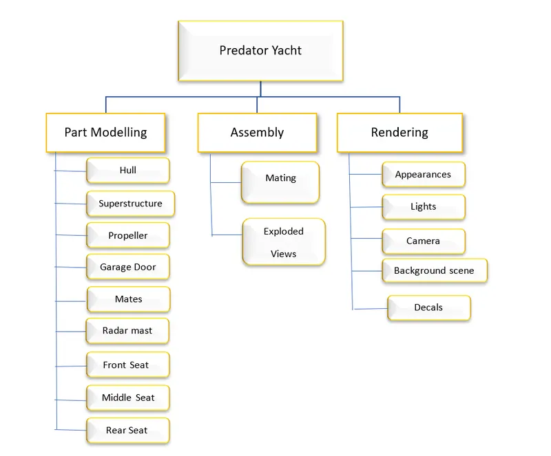
Design Methodology:
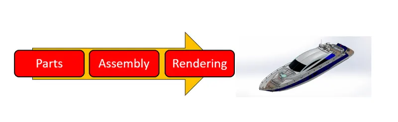
List of commands with their Explanations:
Sketch commands
Line - In sketch line is created by choosing different types like centerline, midpoint line and construction line etc.
Arc - It is a three-pointed arc can be created on basis of positioning points.
Smart Dimensions - The dimensions of any sketches can be changed easily at required situations easily by using this command.
Ellipse - An ellipse is a geometric shape that results from viewing a circular shape in perspective, or from a different vantage point. In simple terms, an ellipse is an oval.
Circle - Circle is sketching tool in SolidWorks. There are two methods of drawing circles, Center Circle and Perimeter Circle. Center circle sketches center-based circles. Perimeter circle sketches perimeter-based circles. These are sketched by defining three points. This type of circles is used when we have to create a circle passing through three points, you have to specify all three points to create this circle.
Sketch picture - This command is useful in inserting required pictures for modelling part. When we insert a picture, the scale tool automatically displays. The scale tool is a construction line with handles at each end. Then use the scale tool to resize the picture.
Properties - It enables the relationship of different sketches at required situations.
Offset - It Offsets one or more sketch entities, selected model edges, or model faces by a specified distance.
Construction Line - It is useful to convert contusions line into dashed line, as well as we can create a line with infinite length without length parameter.
Rectangle - The center rectangle point center rectangle can be controlled easily by using construction lines to corners/midpoints.
Slots - It is Used to develop 4 different types of slots with reference of center axis by adding dimensions Straight Slot & Center Point Straight Slot.
Spline - It is to develop irregular shape objects by assigning several fit points
Trim - Select the trim type based on the entities to delete unrequired geometry.
Extend - It can extend the entities to nearby geometry on basis of required selection.
Mirror - It can create new duplicate objects at required planes and surfaces.
Linear Sketch Pattern - Used to create new reverse duplicate objects about following entities
- Linear pattern: A linear pattern creates a copy of a feature similar to a grid. To define a linear pattern, required things are specify the direction of the patterns, the number of copies in each direction, and the distance between copies.
- Circular Pattern: The circular pattern is very similar to the linear however, instead of patterning along dimensions, it patterns about an axis.
Feature Commands
Extrude Boss/Base - this feature is used to develop solid with reference of sketch or selected sketch contours in one or both directions.
Sketch Plane - To develop solid from sketch plane with specific distance.
Revolve Boss/Base - It is used to create a solid feature by revolving a sketch about an axis. It is mostly used for creating cylinders, pipes and tubes or any solid objects which has an axis.
Loft - It creates a feature by making transitions between profiles. A loft can be a base, boss, cut, or surface. It can be possible to create a loft using two or more profiles. Only the first, last, or first and last profiles can be points. All sketch entities, including guide curves and profiles, can be contained in a single 3D sketch.
Fillet - It creates a rounded internal or external face on the part. It is possible to fillet all edges of a face, selected sets of faces, selected edges, or edge loops.
Section view - In a section view for part or assembly document, the model is displayed as if cut by planes and faces that to specify, for showing the internal construction of the model.
Dome
Extrude cut - This tool is used to remove material by projecting a sketched section normal to the sketching plane. Extrude cut feature helps to remove materials from 3D models, but only in linear manner.
Split - This Feature is used to create multiple parts from an existing part. It is possible to split one or more solid or surface bodies. To split a sketch, the Trimming sketch must extend past the boundaries of the sketch to split.
Axis - It is used to enable temporary axis for any part.
Sweep Boss - It creates a base by moving a profile (section) along a path, according to this profile must be closed for a base feature. The path may be open or closed.
Mirror - It creates a “copy” of an existing object. Additionally, it is possible to choose a plane to mirror parts. In most cases, new plane is created in which our own plane to have the mirror done the way we need.
Appearance - This feature has capability to control the way in which the surfaces of model to look. These can be applied at part, assembly, feature and face of model. All the surfaces of a parts will have an appearance added on them.
Fillet - It creates a rounded internal or external face on the part. It can be added to all edges of a face, selected sets of faces, selected edges, or edge loops.
Chamfer - It is used for assigning smooth edges on solids with five different methods such as Angle-distance, Distance-distance, Offset Face , Face-Face and Vertex.
Draft - Draft tapers faces using a specified angle by selecting faces in the model.
Dome - This feature is used to create one or more domes to the selected planar and non-planar faces. Hence the software has capability to calculate radius of arc as a basis for dome.
Pierce relationship - Pierce relations can be added to sketch points and an axis, edge, line or spline. They are especially useful for ensuring that a coincident relationship is formed between entities of varying axis.
Composite curve - This feature can create composite curves by combining curves, sketch geometry, and model edges into a single curve. These composite curves are used as a guide curve when creating a loft or a sweep.
Shell - The shell tool hollows out a part, leaves open the faces that is selected, the remaining faces and creates thin-walled features on it.
For Example: If we do not select any face on the model, you can shell a solid part, creating a closed, hollow model, you can also shell a model using multiple thicknesses.
Patterns - Used to create duplicate objects from original with specific arrangement.
- Linear Patterns: It is used to create multiple instances of one or more features that can be possible to specify space uniformly along one or two linear paths,
- Circular Patterns: It is used to create multiple instances of one or more features that can be possible to specify space uniformly around an axis.
Surface modelling is a method of creating planar or non-planar complex geometry which has zero thickness. This zero-thickness geometry is known as surface. The surfaces are generally used to create models of complex shapes. We can convert surface models in solid models. We can also tract a surface from a solid model using the tools available for surface modeling.
Surface commands
Sweep surface - These surfaces are generated from a section curve positioned along a path. Various Sweep types are available to extend the sweep surface.
Trim Surface - It is possible to use a surface, plane, or sketch as a trim tool to trim intersecting surfaces.
Surface Loft - These surfaces are generated by multiple 3D Curves or existing edges creating a smooth tangency between the selected curves. Match Points are created between each selection denoting the orientation and path of the loft surface.
Projected Curve - It is a tool used to form 3D curves from two 2D curves from two different planes.
Knit Surface - The Knit Surface tool is used to combine two or more faces.
Filled Surface - The Filled Surface feature constructs a surface patch with any number of sides, within a boundary defined by existing model edges, sketches, or curves, including composite curves.
Extend Surface - For edges, the surface extends along the plane of the edge. For faces, the side of all edges of the face except those connected to another face.
Trim surface - It trims the surfaces where a surface intersects with another surface, a
plane or a sketch.
Ruled surface - Inserts ruled surfaces in a specified direction from edges. Tangent to surfaces, Normal to surface, tapered to vector.
Fillet - A fillet is an internal rounding of edge or corner in a sketch, or an edge on a surface.
Thicken - These feature helps to thicken surface with required dimensions.
Parts of American Predator Yacht:
- Hull
- Superstructure
- Propeller
- Garage Door
- Radar
- Radarmast
- Front Seat
- Middle Seat
- Rear Seat
BLUEPRINT
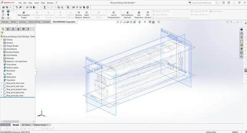
Steps followed for setting up Blueprints:
- At first front plane is selected and enters sketch environment then front view of image is inserted through sketch tools with proper dimensions.
- Then Right plane is selected then enters sketch environment for inserting side view of yacht by applying proper dimensions.
- Next top plane is selected then sketch is selected for inserting bottom view of yacht and fixed by applying certain dimensions.
- Then plane is created by choosing front plane as reference with certain offset distance. It is selected to sketch for inserting back view of yacht as a reference for surface modelling.
- On basis of bottom plane new plane with certain offset distance is created. Then sketch is selected for inserting top view of yacht and further named this plane as top plane.
Description about Designing of parts
Hull
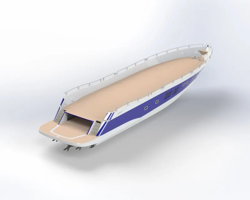
The 'hull' is the portion of the boat that rides both in and on top of the water. The boat hull does not include any masts, sails, rigging, machinery or equipment. This shape of the boat hull greatly affects the way it moves through the water. This hull type allows boats to move through rough water at higher speeds and it provide a smoother ride than other hull types. A hull is the watertight body of a ship or boat. The hull may open at the top (such as a dinghy), or it may be fully or partially covered with a deck. Atop the deck may be a deckhouse and other superstructures, such as a funnel, derrick, or mast. The line where the hull meets the water surface is called the waterline.
- The hull is a watertight body of a vessel which may be open or may be partially covered with a deck.
- Hull has several watertight decks and bulkheads as the major transverse membrane.
- The intermediate member of the hull consists of girders, webs and stringers.
- Depending on the structural arrangements, there may be longitudinal members for strengthening purpose
Baseline - It is a level reference line from which vertical distances are measured.
Bow - It is the front part of the hull.
Amidships – It is the middle portion of the vessel in the fore and aft direction.
Port – It is the left side of the vessel when facing the bow from on board.
Starboard – It is the right side of the vessel when facing the bow from on board.
Stern - It is the rear part of the hull.
Waterline – It is an imaginary line circumscribing the hull that matches the surface of the water when the hull is not moving.
Bridge - The ship’s bridge is the commanding station of a ship. It controls the ship movement through its navigational equipment. It controls important deck machinery, main engine and ship’s navigation system.
Funnel - A Funnel or Stacks is a chimney on a vessel used to discharge engine and boiler smoke.
Accommodation - The accommodation area is the house for crews and lives. It has all the amenities
along with offices, gym, crew cabins, hospital, salon, recreation room, common rooms, laundry and galley.
Funnel Deck - Funnel releases exhaust gases into the atmosphere from engine exhaust room of the ship. It has a similar function to chimneys in factories
Boat Deck - Ship hull structure is covered by the deck floor. There can be multiple decks or deck sections on a ship. The deck at the top which bears maximum exposure to weather is referred to as the main deck or weather deck.
Mast - The mast is a rangy spar arrangement which is elevated vertically to the Centre line of a ship.
Flying Bridge - It is an extended area on top of a weather deck or an open area of the superstructure which provides an unobstructed view of the fwd and aft along with the sides of the vessel to the navigational officers.
Stem - Front-most part of the boat or ship’s bow is termed as Stem of the ship.
Forecastle - The forecastle is one of the foremost parts of the ship of length less than 7% of total deck length.
Foredeck - The foredeck is the forward part of a weather deck, between the superstructure and the main superstructure.
Stern - The stern is aft end structure and designed to provide low resistance, high propulsion efficiency and avoid vibrations.
Poop Deck - It serves as a roof to the cabin constructed in the aft of the ship.
Side Thrusters - These are somewhat like a propeller and fitted on either side of the bow of the ship.
Rudder - Without steering, we can’t move a vehicle in the desired direction; so the propeller propels the ship and rudder steer the ship. The rudder is a flat hollow structure, housed in the aft of the propeller.
Commands used in sketch:
- Lines
- Splines
- Sketch picture
- Offset Entities
- Convert Entities
- Circle
- Rectangle
- Slot
- 3-D Sketch
Commands used in Features:
- Mirror
- Projected Curve
- Sweep Boss
- Extrude Boss
- Fillet
- Shell
- Chamfer
- Extrude Cut
- Reference Planes
- Dome
- Linear pattern
- Split
Commands used in Surfaces:
- Surface Extrude
- Revolved Surface
- Lofted Surface
- Surface Trim
- Surface Fill
- Surface Knit
- Delete Face
Steps for Modelling Hull:
- Initially by using the blueprints as reference required sketch is drawn. Then bottom plane is selected and sketches by using splines and lines are drawn. On midplane lines with appropriate dimensions are drawn.
- The other part of edge is drawn with spline of two midpoints. On basis of these two sketches projected curve is drawn.
- Then midplane is selected for sketching spline and required relations like Equal curvature option is selected. On basis of bottom plane Splines are drawn and adjusted as per the blueprints. Then required relations are added to splines for constraining sketch.
- Then backplane is selected, and lines are drawn to join the two curves that drawn earlier. Pierce relations are added. In same way other ends are joined by using spline.
- The outer structure of yacht is drawn by using loft surface for adding surface between the two curves. Then lower surface is drawn in same way as earlier for making surface to lower part.
- Trim surface command is used to remove an unwanted surface from the part. Then back view of yacht is drawn by using splines and by adding loft feature for adding surface.
- For adding surfaces Surface Extrude is added to bottom part. Then all the surface is selected to knit for merging parts together. Then shell is used to remove the material inside the part. Then some sketches are drawn at back side and extruded it.
- Then these surfaces is selected to draw required sketch and extrude it to add material. In same way the lower part is also drawn sketch then extruded it.
- Required fillets and chamfers are added to edges and faces. Some of the elements like porthole as per reference blueprints at required are drawn and further selected linear pattern to get required number of parts.
- Then by selecting surface of back side stairs are drawn by using required sketches. In bottom required sketches are drawn and offset it then extrude it for required parts.
- As per blueprints all required parts are drawn with required sketches and appropriate dimensions. Some swept boss is used to get required parts.
- Then railings are drawn by using some projected curves and all these are constrained by using fix relation. At one end circle is drawn then it is swept boss to get required pattern by adding material.
- In same way all parts are drawn by using swept boss, revolve and extrude. Then required fillets are added to all parts.
- Sketching of anchor is done by drawing required geometries and adding extrude, fillets and mirror options. Then it is extruded outwards for meting other surfaces of yacht.
- Then Garage part is extracted out from this part by using split features and further saving it as separate file. By using rectangle, it is selected to extrude cut for getting separated from yacht.
- At last all appearances and decals are added to all parts on basis of surfaces, parts and features.
Superstructure
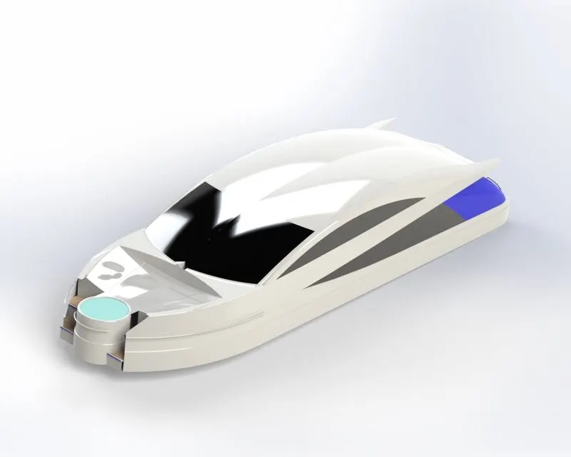
The superstructure covers everything above the substructure, from walls to floors to roofing. The purpose of the superstructure is to enclose and divide space, as well as spread loads safely into the substructure. On water craft, the superstructure consists of the parts of the ship or a boat, including sailboats, fishing boats, passenger ships, and submarines, that project above her main deck. This does not usually include its masts or any armament turrets.
Commands used in sketch
- Sketch picture
- 3D Sketch
- Line
- Spline
- Circle
- Rectangle
- Arc
- Convert Entities
Commands used in Features
- Project Curve
- Reference Curve
- Split
- Split Line
Commands used in Surfaces
- Extruded Surface
- Swept Surface
- Ruled Surface
- Knit Surface
- Trim Surface
- Extend Surface
- Filled Surface
- Lofted Surface
- Revolved Surface
- Fillet
- Chamfer
Steps for modelling Superstructure
- Hull model is inserted for getting deck surface only by selecting surfaces and rename it as required file name. Then line and spline is drawn on basis of blueprint as reference with required dimensions for constraining sketches.
- Then by using surface Extrude these sketches are extruded on basis of surface. Plane is created on this surface and sketches are drawn for doing sweep surface. All these surfaces are knitted by choosing merge results. Fillets are added to these edges.
- Ruled surface is added to one of the edges. Sketches are drawn on midplane for doing trim surface. In same way sketches are drawn on top plane and unwanted surface are selected for trim.
- Then top plane is selected for sketching required edges are chosen for offset. In same way on midplane sketches are drawn and both these sketches are selected for projecting curve.
- By using two 3d sketches edges are joined using lines for creating loft surface. All surfaces are selected for knit. Spline is drawn by using 3d sketch for sweep surface.
- Surface lofts are created at required gaps to fill surfaces. All surfaces are selected to knit by using merge results. By using trim surface, the unwanted deck surfaces are removed.
- Sketch is drawn on one of the surfaces to do extrude cut. Then dome is added to a required surface. Fillets are added at required edges.
- Then on basis of required selections like face, body and features Appearance are added.
Propeller
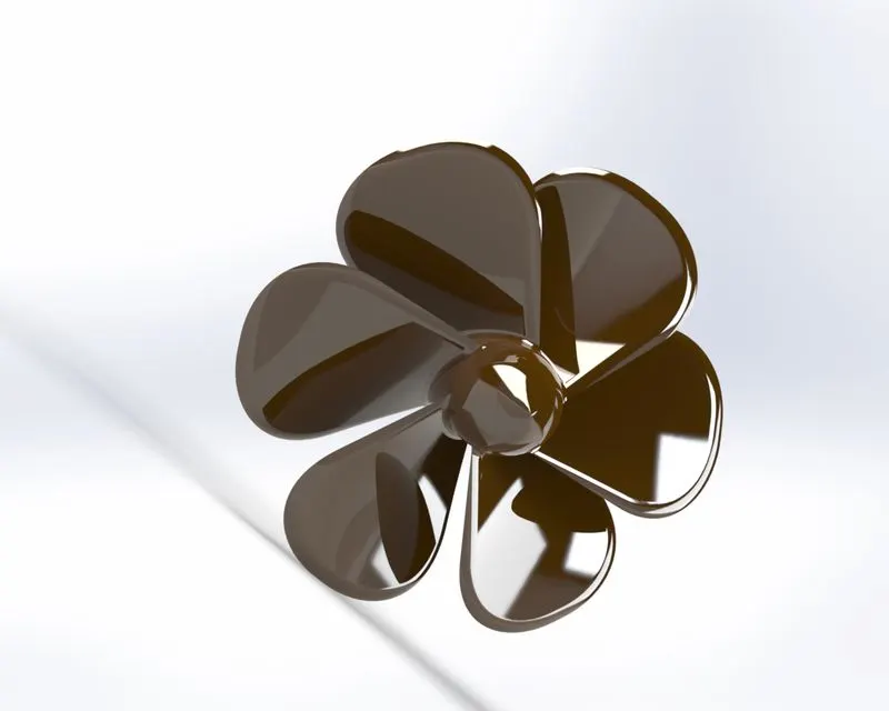
For displacement hull yachts, propellers are generally specified with 2 or 3 blades and available as fixed, folding, feathering or Auto props. The propeller works by turning torque into thrust. In other words, it converts power from the engine into an action. The action of turning the propellers creates force, by moving the flow of water downward and behind the blades. These speeds change the pitch allows the propeller curve to follow the curve of the engine. It also allows better flowing of the boat at low speeds without engaging and disengaging the propeller. Its works on basis of Newton’s second law of motion and Bernoulli’s principle.
Commands used in Sketch:
- Lines
- Spline
- Rectangle
- Circle
Commands used in Features:
- Revolve
- Loft
- Fillet
- Extrude Cut
- Circular pattern
Steps for Modelling Propeller:
- At first required plane is selected for sketching appropriate geometry with proper dimensions. Then required relations are added to be constrain the geometry properly.
- Then the sketch is selected to revolve along its axis. Top plane is selected to draw a rectangle with proper dimensions.
- Required plane is created and sketch is drawn on this plane. Then loft is added between these rectangles and adjusted to get required profile.
- Then fillet is applied to the edges of fan blades. Circle is drawn on center then extrude cut is applied with certain dimension. Fillets are applied to edges of this profile.
- Circular pattern is selected for increasing number of required blades around its face by giving equal spacing. Required appearances are added to whole part.
Garage Door
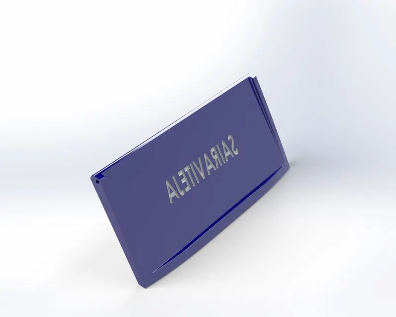
A garage door is a large door on a garage that opens either manually or by an electric motor (a garage door opener). Garage doors are frequently large enough to accommodate automobiles and other vehicles. Small garage doors may be made in a single panel that tilts up and back across the garage ceiling.
Commands used in sketch:
- Lines
- Circle
- Spline
- Text
Commands used in Features:
- Extrude Cut
- Shell
- Fillet
- Mirror
- Planes
Steps for Modelling Garage:
- The earlier part which is made from yacht known as Garage is opened from new file. Then surface is selected for sketching required sketches by appropriate dimensions.
- These sketches is selected and extrude it for removing material. Then shell is created for removing material at the faces. Required fillets are added to edges.
- One of the faces is selected and circle is drawn and extrude cut it. Then whole part is selected and mirror it on basis of selecting one of the bases of part.
- Required appearances are added to the part.
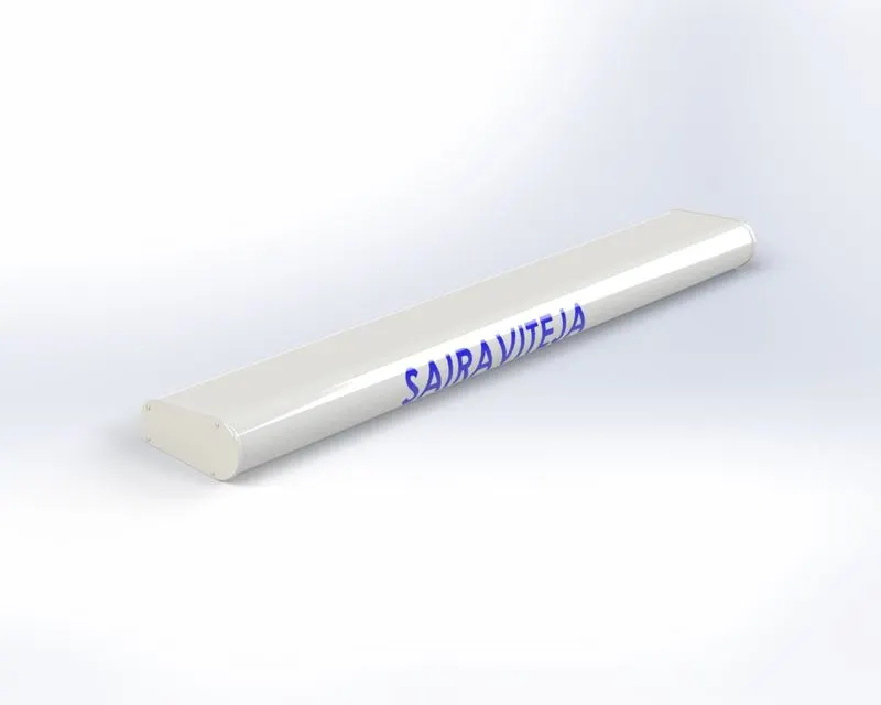
Radar
Radio Detection and Ranging, is used to detect objects and their position relative to our current location. A radar device acts as a major navigation aid for boaters. It helps in detecting boats, birds, landmasses, and weather systems - even if the visibility is less than usual. Radars today are used to detect and track aircraft, spacecraft, and ships at sea as well as insects and birds in the atmosphere; measure the speed of automobiles; map the surface of the earth from space; and measure properties of the atmosphere and oceans.
Commands used in sketch:
- Line
- Circle
- Offset
- Pentagon
- Points
- Sketch text
Commands used in Features:
- Boss Extrude
- Fillet
- Extrude cut
- Sketch pattern
- Mirror
- Split line
Steps for Modelling Radar:
- Initially required plane is selected for sketching the required geometry with appropriate dimensions. Then the sketch is selected to extrude by dimensioning.
- Then fillets are applied to edges of part with dimensions. The edge of sketch is selected to offset from above sketch. These sketches are Extrude by required dimension.
- Then these sketches is offset to inside of part. Then circle is drawn on this profile edges and it is extruded with required dimension. Fillet is added to this edge.
- Polygon is drawn on this surface and extrude cut the profile with proper dimensions. Some of the pints with appropriate dimensions to get constrain sketch are drawn.
- Sketch driven pattern is selected to get the same bodies to be positioned at required path. Then whole thing is mirrored by selecting appropriate plane to be formed.
- By using ketch tools required text is written on face of body. Then required appearance added to part.
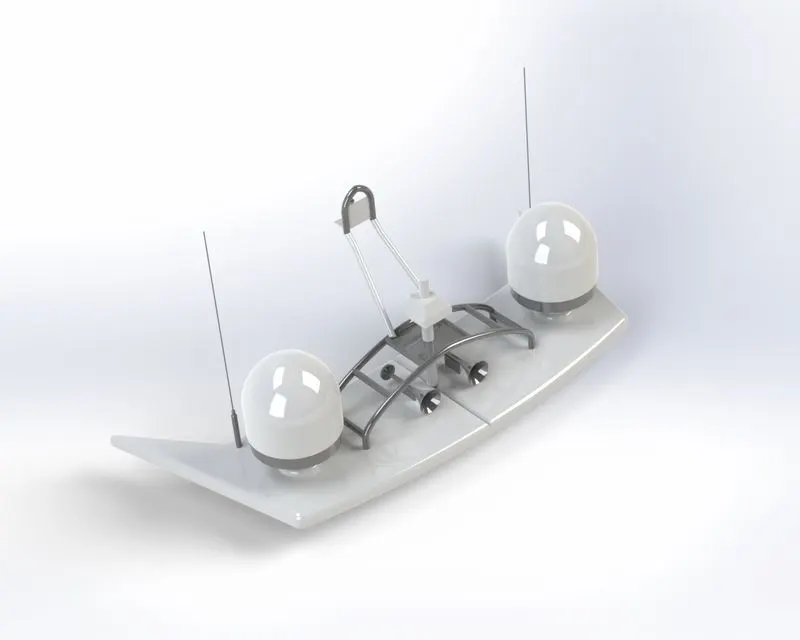
Radarmast
They are electronic navigation instruments that use a rotating antenna to sweep a narrow beam of microwaves around the water surface surrounding the ship to the horizon, detecting targets by microwaves reflected from them, generating a picture of the ship's surroundings on a display screen. These radars are the best collision avoidance system ever developed for the recreational boater. Radar systems helps us to see during darkness, fog and stormy weather conditions.
Commands used in sketch
- Sketch picture
- Line
- Spline
- Rectangle
- Arc
Commands used in Features
- Extrude Boss/Base
- Lofted Boss/Base
- Revolved Boss/Base
- Swept Boss/Base
- Reference plane
- Projected Curve
- Fillet
- Mirror
- Dome
- Shell
Steps for modelling Radarmast:
- At first blueprints file is opened and save it as with required file name. Then insert part by selecting only surface. Sketch is drawn on midplane with required dimensions.
- Plane is created and required sketches are drawn as a reference of blueprints. Extrude the sketch with required dimensions. Then fillets are added to edges of part. Sketches are drawn for creating Revolved boss.
- Sketch is drawn on surface by using circle for creating extrude boss. Plane is created, and sketch is drawn for applying swept boss. On this surface circles are drawn and extrude it to other surfaces.
- Then on basis of one of the basis whole part is selected to mirror along its face by selecting knit surfaces. Dome is added to edge surface of horn.
- Finally, appearances are added to all required parts on basis of face and features.
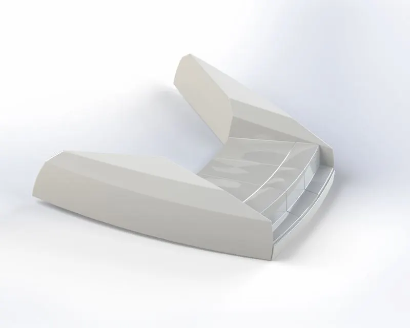
Front Seat
Front seats feature two connected seats that are connected from one and other. They have facility like built in storage unit. These lounge seats also fully recline right back to make it easier for us to kick feet up and get more comfortable. It is placed before the superstructure and consists of sun pads to rest on it.
Commands used in sketch
- Sketch picture
- Line
- Splines
- Circle
- Arcs
Commands used in Features
- Extrude cut
- Fillet
- Chamfer
- Revolved Boss/Base
- Mirror
- Dome
Commands used in Surfaces
- Extruded Surface
- Lofted surface
- Trim Surface
- Filled Surface
- Knit Surface
- Revolved Surface
- Swept Surface
Steps for modelling Front Seat:
- At first blueprints file is opened and remnant it as required. Then by using insert (part) option hull file is opened by selecting surface bodies. All other blueprints are hide and required blueprint is selected to unhide.
- As a reference of blueprint sketches are drawn using splines. On basis of this spline as reference plane is created. Sketches are drawn on this plane for creating surface sweep along this path.
- The ends of surface sweeps are connected through lines by adding pierce relations. Then extrude the surface on basis of vertex as a selection. Trim the unwanted surfaces by using natural selection.
- All these edges are selected for creating surface fill. Then create new sketch on midplane by giving dimensions for constrain geometry. Some gaps are filled by using surface loft option. Trim the unwanted surface by choosing proper trim tools and knit all surfaces.
- Chamfers are created at edges. Sketches are drawn on surface and revolve it as per required dimensions.
- Offset a required entities and trim unwanted sketches. On basis of top view by selecting convert entities sketch is created. Then use Extruded cut up to body as a selection.
- Fillets are added to all edges. Then whole part is selected and mirror it by taking one of the edges as reference. Appearances are added to all parts.
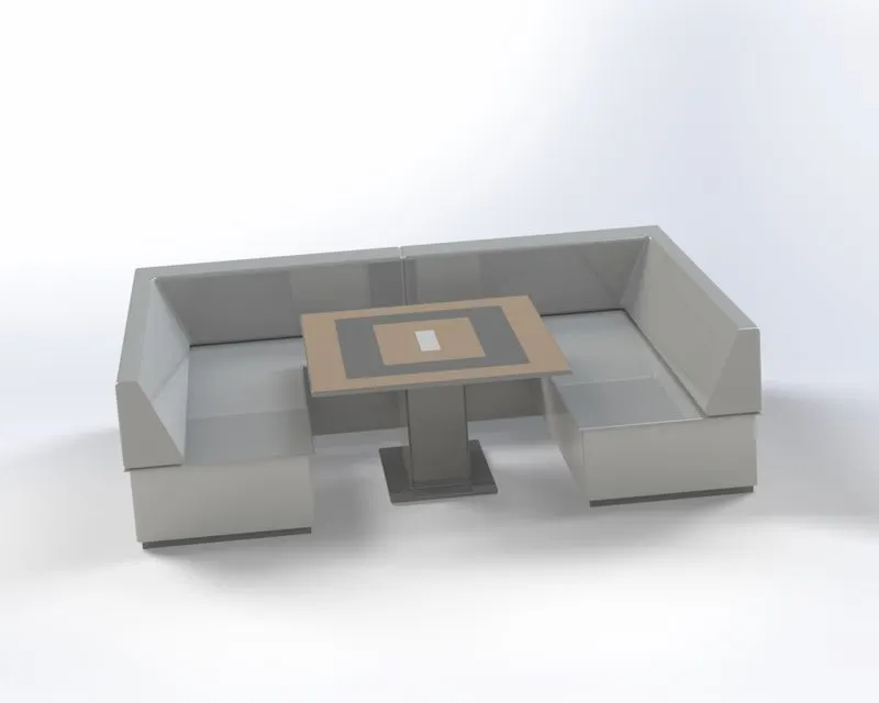
Middle Seat
In this model Middle seat is placed just behind the superstructure. It consists of a luxury dining table. Sometimes useful for casual meetings with co-passengers.
Commands used in sketch
- Sketch picture
- Line
- Rectangle
Commands used in Features
- Extrude Boss/Base
- Chamfer
- Fillet
- Mirror
- Reference plane
Steps for modelling Middle Seat:
- At first blueprints file is opened and remnant it as required. Then by using insert (part) option hull file is opened by selecting surface bodies. All other blueprints are hide and required blueprint is selected to unhide.
- Then required sketch is drawn on surface and extrude it Required entire are offset inwards. These sketches are selected to get Extruded. On choosing this as reference new plane is created.
- New plane is created and sketch with appropriate dimensions are drawn and extruded. Chamfers are added to edges of seats for proper comfort.
- Fillets are added all edges of pillows. Then whole part is selected and mirror it along its edge as a reference by giving knit surfaces and merge options. Fillets are added all this edge.
- Then sketching of table starts by selecting hull surface. Rectangle with proper dimensions are added and extrude it. By using this Rectangle as reference offset this entity inwards and extrude this sketch.
- Appearances are added to all parts on basis like face, Features and bodies.
Rear seat:
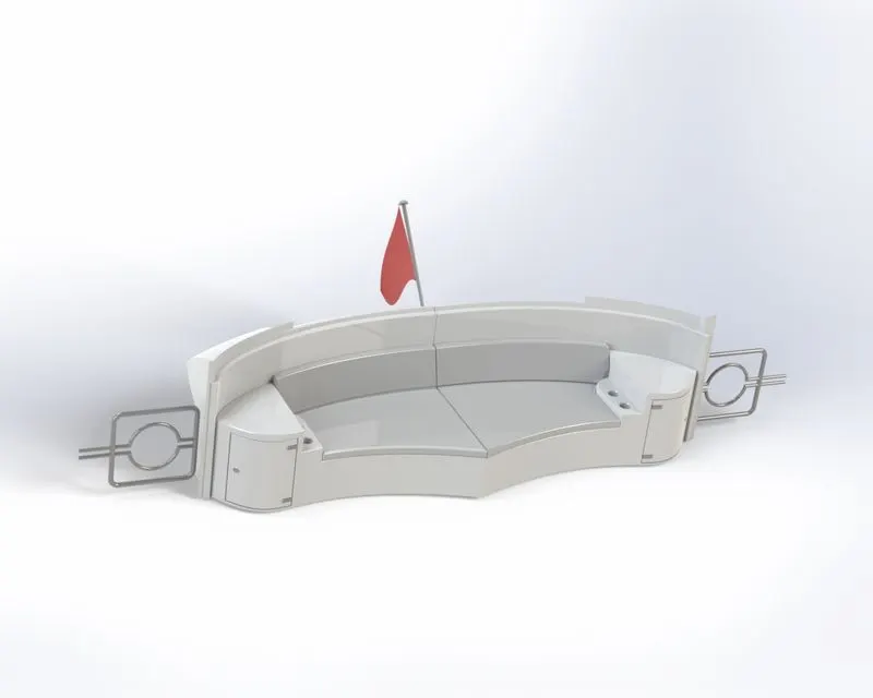
It is placed at end of deck surface. This consists of locker rack and steel doors for stairs. It also has facility to place flag as it is end part of yacht. It also consists of placing glass or mugs which facilitates comfortable for passengers.
Commands used in sketch
- Sketch picture
- Line
- Spline
- Circle
- Arcs
- Rectangle
Commands used in Features
- Reference plane
- Extruded Boss/Base
- Revolved Boss/Base
- Fillet
- Mirror
Commands used in Surfaces
- Swept Surface
- Extruded Surface
- Offset Surface
- Filled Surface
- Knit Surface
- Ruled Surface
- Lofted Surface
Steps for modelling Rear Seat:
- At first blueprints file is opened and remnant it as required. Then by using insert (part) option hull file is opened by selecting surface bodies. All other blueprints are hide and required blueprint is selected to unhide.
- By choosing midplane for sketching and blueprints as a reference splines are drawn with proper dimensions. plane is created on basis of this sketches. Then spline is connected with this sketch for creating sweep surface.
- Surface Offset is created for this surface with required dimensions. Unwanted surfaces are removed by using trim surface. Ruled surface is selected for one of the edges by choosing tangent to surface. All these surfaces are knitted.
- Plane is created on basis of one of the edges by using vertex points. Spline is drawn on this plane by using some dimensions for constraining sketch. Then sweep surface is selected on selecting the earlier sketch.
- Extrude surface is applied to the sketches for intersecting the other surfaces. Trim surface is used to trim all unwanted surfaces further knit all surfaces.
- Surface loft is added to fill the surface between two edges. Then inner surface is extruded by converting bottom sketches for reference. Bottom of the surface is also filled by using loft surface.
- Then some splines are added for sketching flag by using different 3D-Sketches.Loft surface is used to create surface between them. Chamfers and fillets are added at required edges.
- Railings is created by using swept boss and selecting earlier sketch as reference. Then whole part is mirror by selecting one of its edges as a reference.
- Appearances are added to all parts by selecting suitable colors.
Commands used in Assembly:
- Insert Components
- Mate
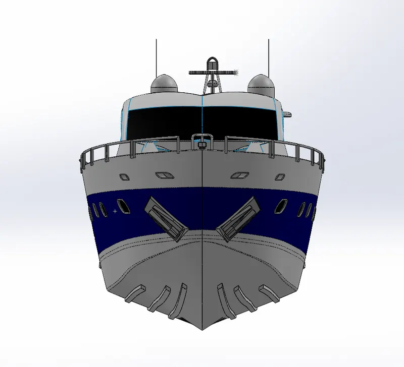
Front view:
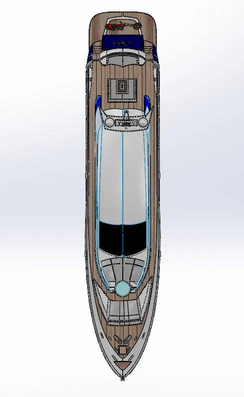
Top view:
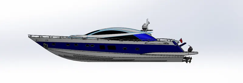
Side view:
Isometric view:
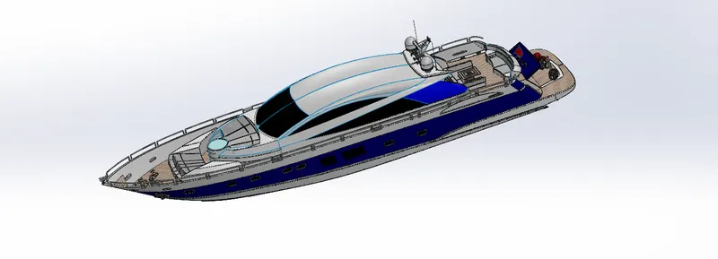
Camera view:
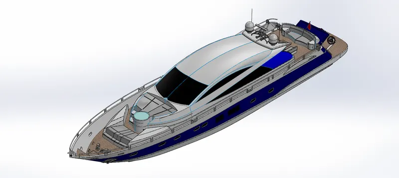
Steps followed for Assembling Yacht:
- Initially hull is inserted using insert option and placed in required position. Then superstructure is inserted and fixed at top of hull.
- Then Radarmast is inserted and placed on top of superstructure at back. Front seat is placed beyond superstructure above the hull.
- Middle seat is placed at backside of superstructure and coincident with hull. Rear seat is place backside nearby edge of hull by applying coincident relation and by giving required dimension for distance.
- Coincident relation is applied between midplanes of Rear seat and hull. Then Garage door is inserted by applying coincident relation is applied between midplane of hull and right plane of garage door. Then Concentric mate is applied at required position of hull.
- Propellers are inserted and applied Concentric and coincident relations. In same way two more propellers are inserted and placed in required positions.
- Radar is inserted and applied concentric and coincident mates to one of the structures of Radarmast.
Rendering
Rendering or image synthesis is the process of generating a photorealistic or non-photorealistic image from a 2D or 3D model by means of a computer program. The term "rendering" is also used to describe the process of calculating effects in a video editing program to produce the final video output.
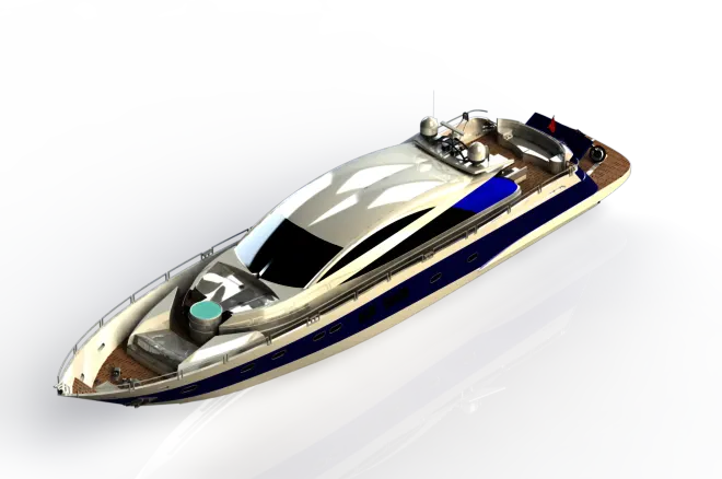
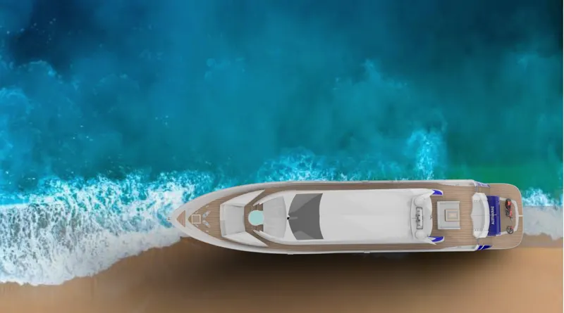
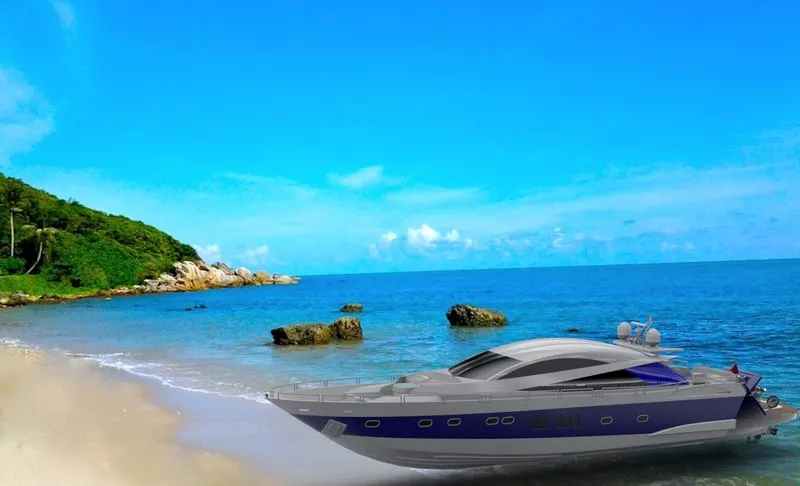
Rendering of American Predator Yacht is done by using PhotoView-360 and Solidworks Visualization.
PhotoView-360
PhotoView-360 is a visualization and rendering solution included with SOLIDWORKS Professional and SOLIDWORKS Premium. It Provides a highly interactive environment for viewing designs as well as for creating photo-realistic renderings that can be used to showcase our designs.
Lighting:
PhotoView-360 proof sheets let you select lighting settings by viewing the effects of a range of settings in a series of proof sheets. Each image represents a different setting for our primary PhotoView-360 lighting. Rendering brightness, background brightness, and scene reflectivity are controlled by the PhotoView-360 Scene Illumination Proof Sheet, a dialog box that lets you quickly see a wide range of variations of these parameters.
Scenes:
By adding PhotoView-360 in, scenes it provides a realistic light source, including illumination and reflections, requiring less manipulation of lighting. The objects and lights in a scene can form reflections on the model and can cast shadows on the floor.
Decals:
A decal is a 2D image applied to a model. These decals can be used to apply warning or instruction labels to models. These can also be used to create model details that can effectively represent with an image instead of with the model geometry, such as a car grill or a picture frame.
Options:
The PhotoView-360 Options Property Manager controls settings for PhotoView-360, including output image size and render quality
Output:
Then rendered images from photoview-360 are monitored on screen and can be saved to our files.
Workflow
- With a model open, click Tools > Add-In and add in Photo-View 360.
- Start a preview in the graphics area or open the Preview window to see how changes for making the model that affects the rendering.
- Edit appearances, the scene, and decals.
- Edit lights. By default, lighting is off in Photo-View. With lights off, you can use the realistic lighting provided by scenes, which is usually enough for rendering. You typically need additional lighting in Photo-View to illuminate occluded spaces in the model.
- Edit Photo-View Options.
- When we are ready, perform a final render either now (Photo-View > Final Render) or later (Photo-View > Schedule Render).
If you have not added a camera or turned on perspective view, which provide more realistic, higher quality renderings, a dialog box appears. It allows us to turn on a camera or perspective view from the dialog box or continue without them.
- Providing detailed adjustments in the Final Render Window.
SolidWorks Visualization
SOLIDWORKS Visualize allows us to leverage our 3D CAD data to create photo-quality content in the fastest and easiest way that we can from images to animations, interactive web content, and immersive Virtual Reality that can brings our products to life. SOLIDWORKS Visualize is the “camera” for our CAD data.
SOLIDWORKS Visualize Boost is a service that allows us to distribute rendering from a computer running SOLIDWORKS Visualize Professional to one or more computers on a network. You can perform other tasks on your machine while the rendering is being carried out, and the final rendered images are available sooner. Images can be rendered on a single machine, or on a cluster of several machines running Visualize Boost.
SOLIDWORKS Visualize products (formerly known as Bunk speed) provide a suite of standalone software tools that combine industry-leading rendering capabilities with design-oriented features and workflows for designers, engineers, marketers, and other content creators. It is possible to import SOLIDWORKS, and other CAD formats to create compelling, highly realistic content.
Isometric view:
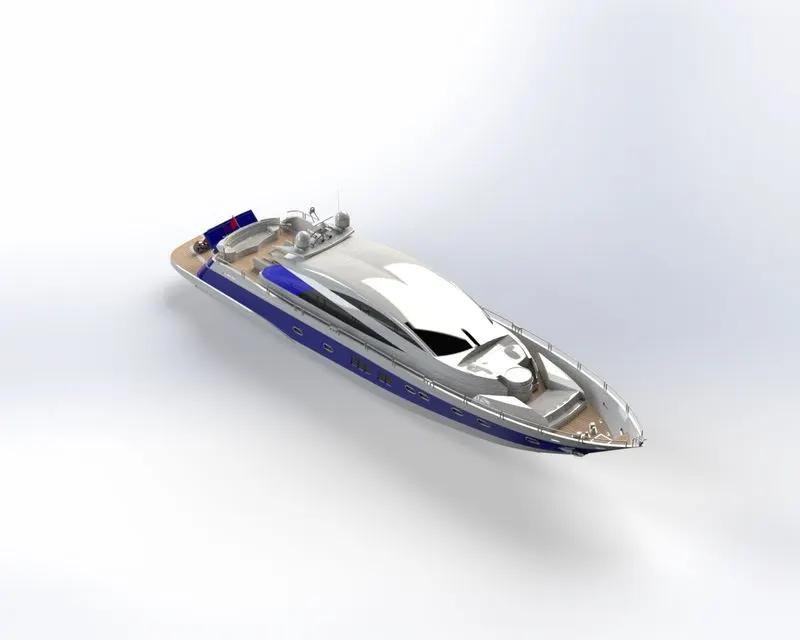
Top View:
Side view:
Rendering Images
To render output to a Visualize Boost cluster:
- In SOLIDWORKS Visualize Professional, open a model and click Tools > Render, or in the main toolbar, click Output Tools
- In the Output Tools dialog box, under the Render Settings area, click Power Boost. The Cluster name displays.
- Set the Render Mode. We can set a time limit or select Quality and enter a number of Passes. The default of 500 passes is adequate for most render jobs.
- To start rendering at a later time, select Send to Queue. The job is sent to the SOLIDWORKS Visualize Queue and does not complete until we click Start Queue in the Queue Client.
- If we are ready to render, select Show Progress to monitor the rendering process. Then click Start Render.
We can click Pause, Save Now, or Cancel to stop the rendering.
Conclusion:
Thus Design, Assembly of American Predator Yacht using solidworks & Rendering using photoview-360 and solidworks visualization has been done.