Fender Design - Wheel Arch Challenge
FENDER WHEEL ARCH CHALLENGE
AIM- Calculate the Wheel Arch gap at required points and check whether the car passes the European standard.
FENDER WHEEL ARCH
Wheel arch is a semi-circular part of the fender positioned above the wheel of the vehicles. The design of the wheel arch of the fender in such a way that to shield the wheels throwing stones, muds, snow or water to the pedestrians & also protect the passenger compartment. This also not only protect the engine compartment for any debris going inside & damage the mechanical components, BIW areas. The are different design standard setup in different parts of the countries which has been implied for the safety standard for pedestrians & for the vehicles.
There are 3 rule & regulation standards to design the fender wheel arch-
- JAPAN STANDARD
- EUROPEAN STANDARD
- S/AMERICAN STANDARD
So, lets discuss about all the 3 standards to design the wheel arch
- JAPAN STANDARD
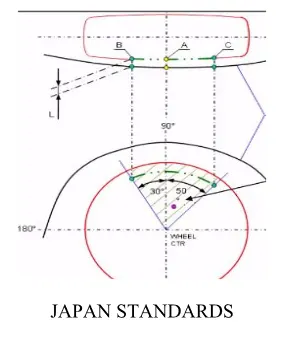
- Measure clearance ‘L’ of tire, hub, cap & fender in 3 different positions within area & produce clearance.
- Clearance must be greater than 5mm in all the three positions (i.e., ‘A’, ‘B’,’C’).
- The value of ‘A’ shall be more than 5 mm at a line 30 degree forward & 50 degree backward from the central vertical axis of the wheel.
- EUROPEAN STANDARD
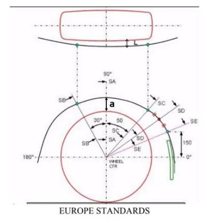
- Measure CL ‘L’ at section SA-SA, SB-SB, SC-SC, SD-SD, SE-SE & produce CL.
- At all 5 section the CL ‘L’ value should e greater than 10mm to satisfy the European regulations.
- The value ‘a’ be more than 5mm at a line 30 degree & 50 degree backward from the central vehicle axis of axis of wheel.
- U.S/AMERICAN STANDARD
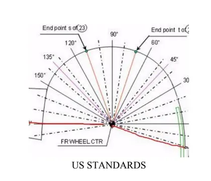
- Make clearance & check details on all position from 100 degree to 100 degree to make the clearance.
- All values should be greater than 5mm to satisfy the U.S/American regulations.
- The value ‘a’ shall be more than 5mm at line 30 degree forward & 50 degree backward from the central vertical axis of wheel.
METHODOLOGY OF DESIGNING WHEEL ARCH IN EUROPEAN STANDARD
- The skin data was given already & need to calculate whether it is reaching the match of the European standard.
- Create the datum plane on the middle of the wheel.
- Sketch the design on the new datum plane which is generated.
- Draw horizontal & vertical perpendicular axes from the centre of the wheel circle.
- Draw 30 degree forward from the central axis line & 50 degree from the centre.
- Make a 150mm line from the horizontal axes to the end point of the fender arch.
- Extent a line to this end point on the fender arch from the centre of the wheel.
- Make a line that exactly between 50 degrees line & the line made on the 150mm point.
- Offset the fender arch
- Mark the point on the fender arch where the lines are intersecting where 5 points are generated.
- Projects the points on the fender arch through projection curve.
- As a result, need to calculate the distance between the actual point & projected points.
Now let us measure the distance between the 5 sections-
- SECTION SB-SB
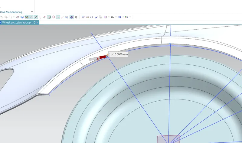
EUROPEAN STANTARD DISTANCE- More than 10mm
CALCULATING MEASURING DISTANCE= 10mm
RESULT – PASS
- SECTION SA-SA
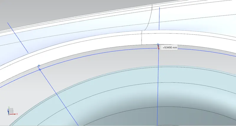
EUROPEAN STANTARD DISTANCE- More than 10mm
CALCULATING MEASURING DISTANCE= 9.949mm
RESULT – FAIL
- SECTION SC-SC
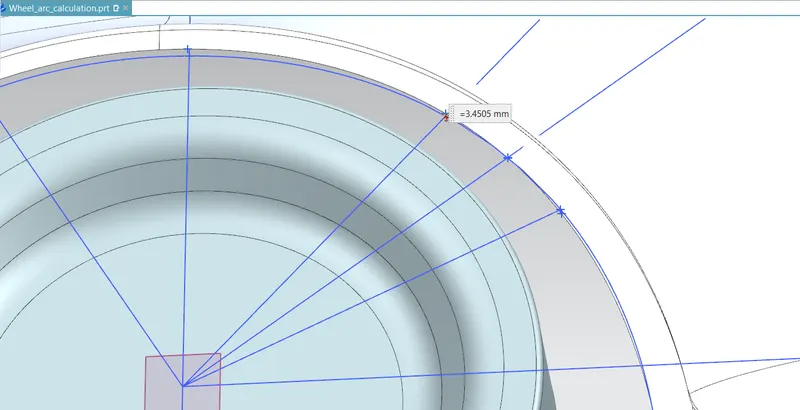
EUROPEAN STANTARD DISTANCE- More than 10mm
CALCULATING MEASURING DISTANCE= 3.4505mm
RESULT – FAIL
- SECTION SD-SD
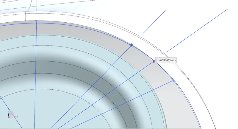
EUROPEAN STANTARD DISTANCE- More than 10mm
CALCULATING MEASURING DISTANCE= - 0.74145mm
RESULT – FAIL
- SECTION SE-SE
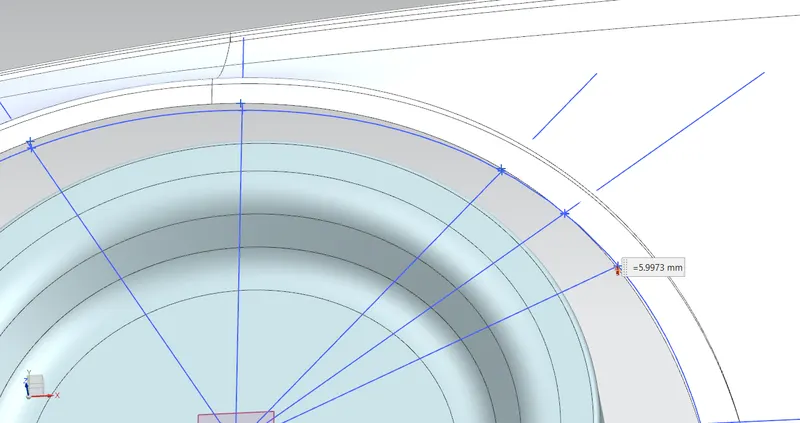
EUROPEAN STANTARD DISTANCE- More than 10mm
CALCULATING MEASURING DISTANCE= - 5.9973mm
RESULT – FAIL
OBSERVATION TABLE-
|
SL NO |
FROM OUTER CURVE OF FENDER |
EUROPEAN STANDARD MEASUREMENT DISTANCE |
CALCUTATING MEASURING DISTANCE |
RESULT |
|
1 |
POINT SB |
>10MM |
10MM |
PASS |
|
2
|
POINT SA (Centre axis) |
>10MM |
9.949MM |
FAIL
|
|
3 |
POINT SC |
>10MM |
3.4505MM |
FAIL |
|
4 |
POINT SD |
>10MM |
-0.74145MM |
FAIL |
|
5 |
POINT SE |
>10MM |
-5.9973MM |
FAIL |
CONCLUSION-
The given data does not meet with European standard, so the result of the design is considering a FAILURE.