Fender Design - Wheel Arch Challenge
Fender is a fibre/plastic component which shields the wheels and restricts mud,water,stones etc that gets carried along the rotating grooved tyre. The grooves are deliberately cut on the tyres so as to provide a smooth path for the road substances to get channelled out resulting in better traction. The substances tend to stick in these grooves for a while before getting thrown. Centrifugal force is responsible for tangential outward path taken by the flying substances from the tyre. This results in heavy bombardment of stones and other roads substances that could result in both pedestrian and the vehicle occupant to get seriously injured. To avoid the same, fender is provided both on two wheelers and four wheelers.
BIKE
A typical fender on a bike Bajaj Dominar 400 looks like this:-
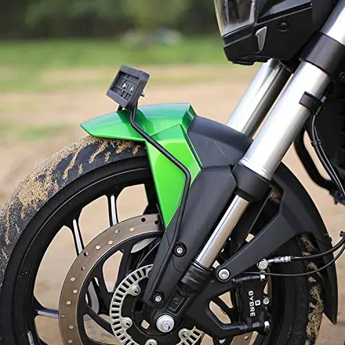
On a bike, fender is among the first part that comes in contact with the flowing air while riding. If the fender is oddly designed then it can restrict a lot of air resulting in air drag plummeting the overall performance of the bike. Along with this, fender also plays a role of channeling the air through the wheels and bike side panels for cooling purpose. The fender is designed aerodynamically to satisfy the purpose of the manufacture.
CAR
A typical fender on a car (Nissan 350Z) looks like the one shown in the pic. As it is known to us that a fender is mounted over a wheel for the fulfilment of the purpose, so a car has total 4 fenders for the 4 wheels. Two on the rear and two on the front. Mostly the rear fenders are integrated with the body while the front fenders are fitted seperately.
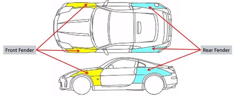
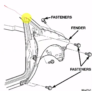
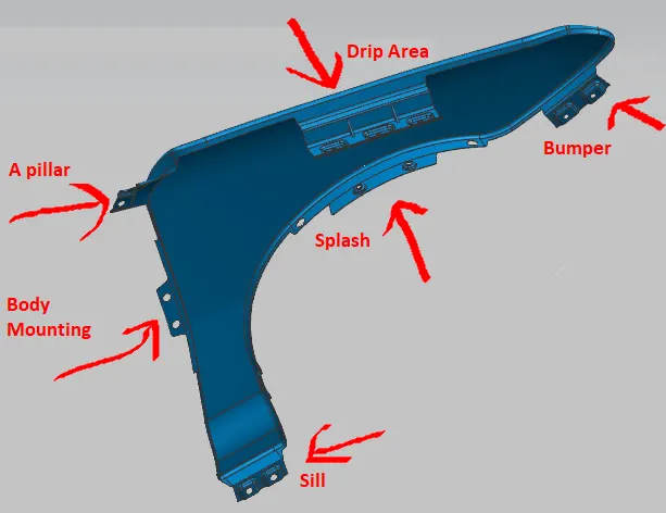
Fender of a car is also designed keeping both aerodynamics and safety in mind just like the one on a bike. There are 2 surfaces of a fender. The outer surface is the styling one which provides the continuity to the other smooth lines of the adjacent body parts. Fender is fitting with a total of 6 flanges that gets fastened on the car on 6 different points which are 1) body, 2) drip 3) sill 4) cowl 5) A-pillar 6) bumper.
Wheel arch
It is the curved region of the fender that is present right above the wheel. Wheel arc is the region which gets the hitting of the flying particles when the vehicle is running. Different countries have their own regulations of the wheel arch and the car that is going to be a part of that country's traffic must pass the regulations. Only if the car passes the regulation, it is given the permission for street use. A car for better sales, should operate in as many countries as possible which makes it important to create the fender(in this case) with maximum regulation parameters covered of different countries at once.
The basic moto of the regulation is to reduce more chipping of the particles from flying free in air which may injure the pedestrians. To avoid this, the wheel should be at some distance inside the fender when looked from the front. The regulations depend from the road conditions of that country. There are 3 types of regulations followed across the globe which are 1)US regulations 2) Japan regulation 3) European regulation.
1)USA regualtion
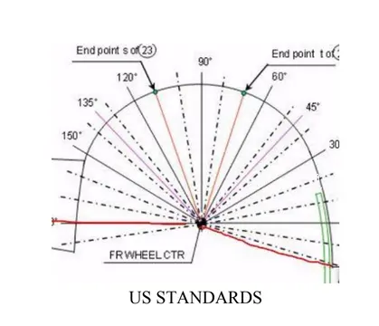
*)Make clearance check details on all positions from -100* to 100* & make the clearance check table.
*)All values should be greater than 5mm to satisfy the regulation.
*)The value of 'a' shall be more than 5mm at a line 30* forward and 50* rearward from the central vertical axis of axis of wheel.
2)Japan regulation
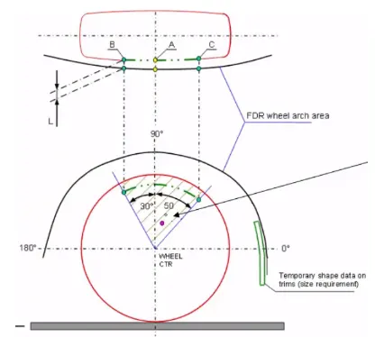
*)Measure clearence L of tire , hub, cap & fender in three different positions within area K and produce clearance check chart to validate.
*)Clearance must be greater than 5mm in all the three positions.
*)Well guard requirement: the value should be more than 5 mm at a line 30* forward and 50* rearward from the central vertical axis of axis of wheel.
3)European regulation
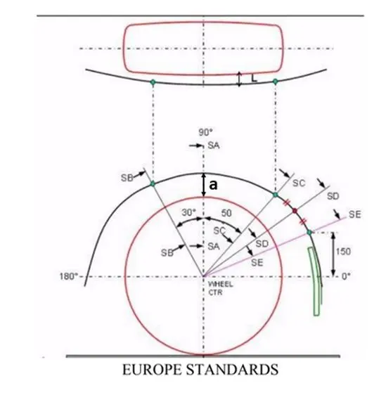
*)Measure CL L at section SA-SA SB-SB SC-SC SD-SD SE-SE and produce CL check chart to validate.
*)At all five sections the CL L value should be greater than 10mm to satisfy the european regulations.
->)Procedure followed over here is as follow:-
1)Create a datum plane taking the wheel plane as the reference plane.
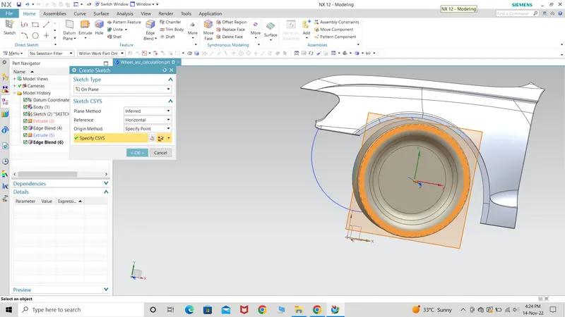
2)Taking the wheel centre draw a sketch on the datum plane creating a horizontal and a vertical line which would be used as the reference to make the other lines angled to these 2 lines.
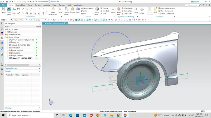
3) By using rapid dimensions, I have created 30 and 50 degree line from the vertical line.
4) By using derived lines, I have taken 30 degree and 50 degree line as reference and later bisected the line as per regulations.
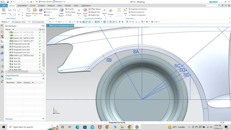
5) After naming the points, the points are projected on the fender and later the distance is measured by using dimensions in analysis. The distance measured are as follows:-
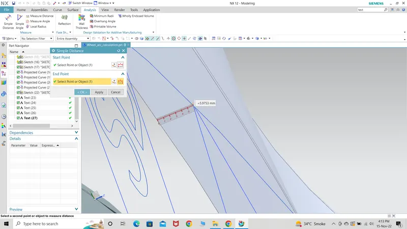
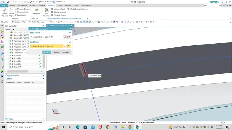
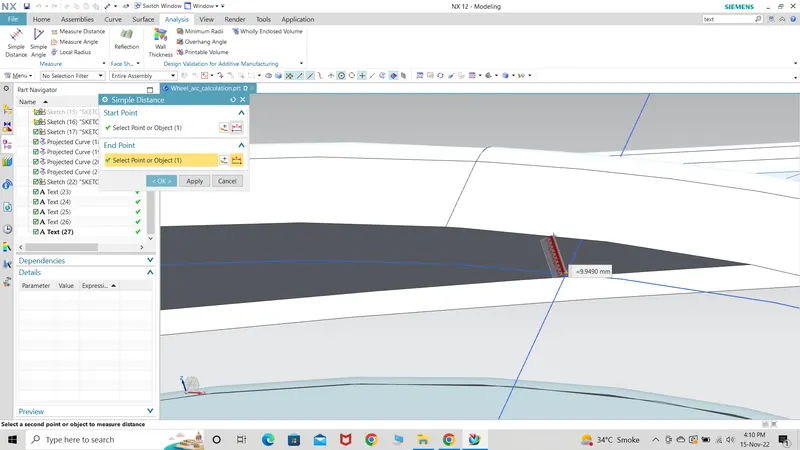
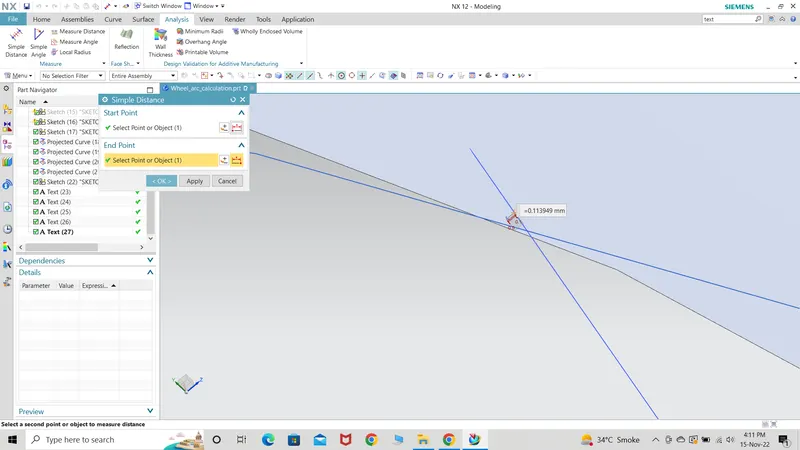
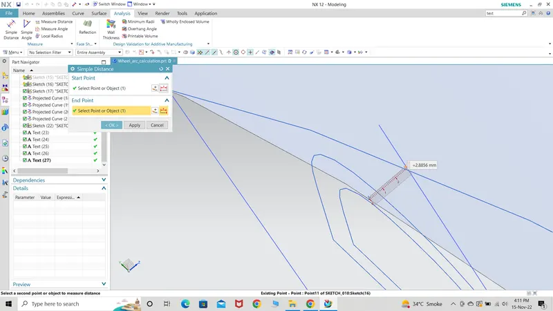
The results are as follows:-
| SECTION | CALCULATED CLEARANCE IN MM | EU. REGULATION CLEARANCE IN MM | RESULT |
| SA | +9.940 | +10 | FAIL |
| SB | +10 | +10 | PASS |
| SC | -0.113 | +10 | FAIL |
| SD | -2.88 | +10 | FAIL |
| SE | -5.97 | +10 | FAIL |
Conclusion made out the table is that the design is a failed one and doesn't pass the European fender design regulation standards. Negative sign indicates that the wheel is protruded out of the fender region when looking from the front and similarly positive sign indicates that the wheel is inside the fender region. To pass the regulation standards, the design team needs to work on the design and improve the results to minimum 10mm.