Fender Design - Wheel Arch Challenge
Fender - Wheel Arch
- The shape of the wheel arches allows the front wheels to steer without rubbing on the bodywork.
-
The shaped part of the bodywork of a car or other vehicle that allows the wheel to be accessed, and in the case of front wheels, enable them to be steered.
-
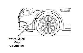
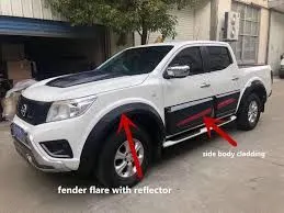
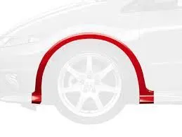
The wheel arch is the semi-circular part positioned above the wheel of a vehicle. The most important body change was that the front wheel arch was cut higher into the fender. Corrosion had occurred around the splash plate at the back of the wheel arch.
-
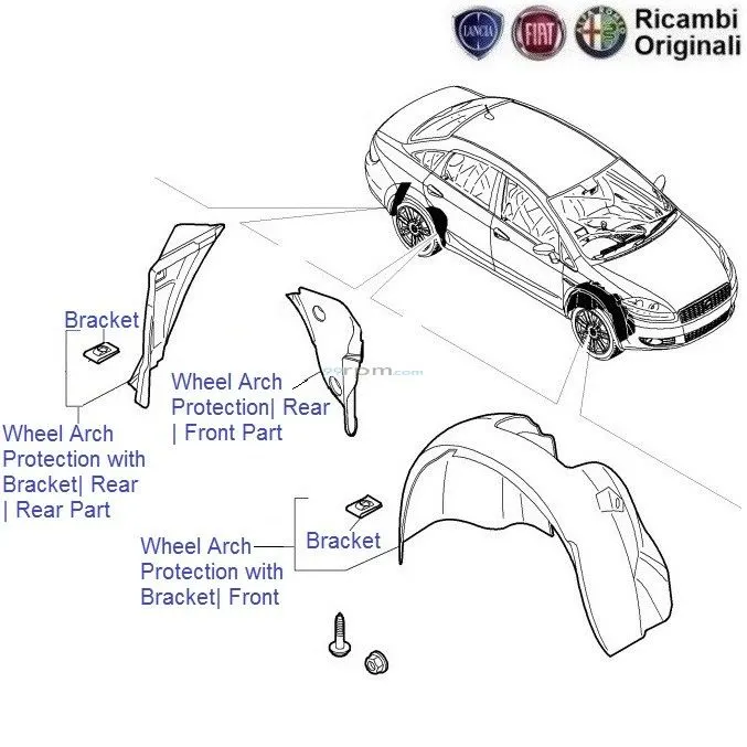
The wheel arc is an integrated part of a fender assembly. It is a semi-circular part which is positioned above the wheel of a vehicle. In some countries, it is also called as an inner fender.
Material
Previously in late 60’s–90’s inner fender or wheel arch were made of sheet metal. To reduce weight of the car and achieve high fuel economy of the car companies all around the world started to reducing the overall weight of the car. And by adding Baffle to the fender design it gives much more good looks to the car and wastage of sheet in manufacturing the fender has being also reduced. The most commonly used wheel arch is of plastic material. If the vehicle with metal inner fenders is used, there's a good chance winter salt and moisture has caused them to develop some rust in hard-to-spot areas. Improper repairs after an accident can also accelerate corrosion here as well. It's important to note that metal inner fender parts are typically welded to each other, and to the body of the vehicle.


Designing Wheel Arch
The important parameter which is considered in the designing of wheel arch or wheel is the clearance between wheel and fender during the vehicle bump conditions.
Standard Regulation for designing Wheel Arc -
There are certain standards regulations all over the world for the Clearance between the Fender and the Wheel they are as follows -
1. Japanese Regulation Rsequirement
In Japanese regulation, the clearance between tyre and fender must be greater than 5mm the projected points to be measured are at an angle 30° forward & 50° rearward respectively.
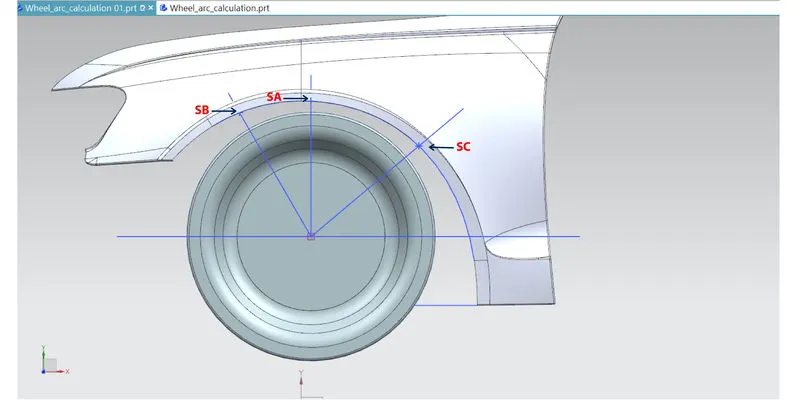
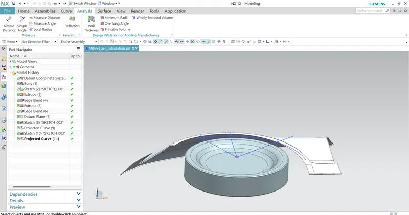
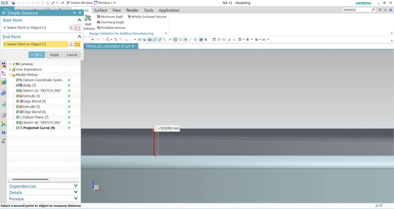
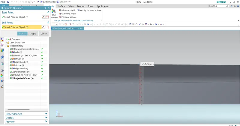
| MEASURED POINTS | SA | SB | SC |
| REQUIRED LENGTH | 5mm | 5mm | 5mm |
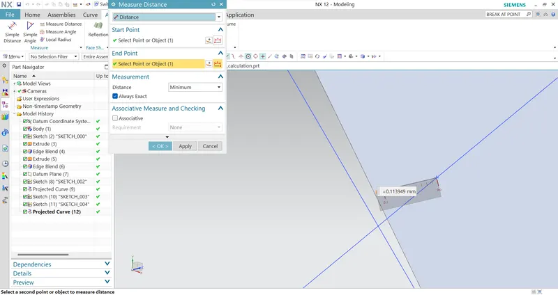
| ACTUAL LENGTH | 9.490mm | 10mm | -0.113949mm |
| REMARKS | PASS | PASS | FAIL |
Conclusion
As per Japanese regulation, the clearance between tyre and fender must be greater than 5mm. Thus, at point c, the clearance value is in negative value which denoted interference and hence the modifications are to be carried out.
2. European Regulation Requirement
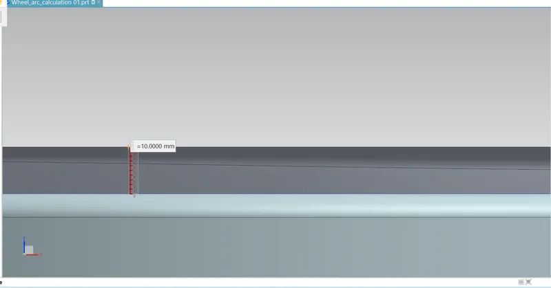
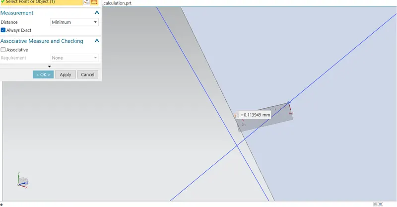
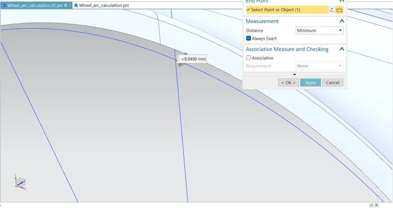
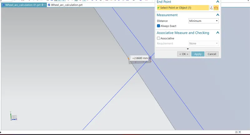
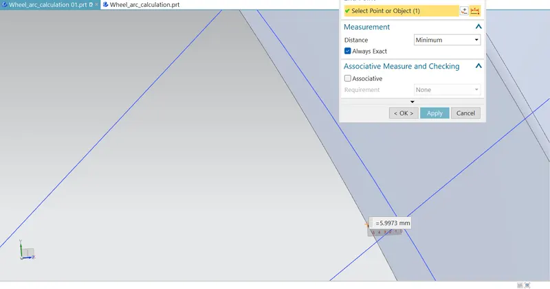
As per European regulation, the clearance value between fender and tyre profile must be greater than 10mm. The value is measured in projected point at an angle 30° forward and 50° rearward respectively. The measurement took in five different positions of the tyre at point a & b the clearance is acceptable. But at point c, d & e there is a negative sign which denoted the interference of wheel arch with a tyre.
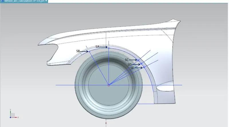
| MEASURED POINTS | SA | SB | SC | SD | SE |
| REQUIRED LENGTH | 10MM | 10MM | 10MM | 10MM | 10MM |
| ACTUAL LENGTH | 9.9490MM | 10MM | -0.113949MM | -2.8680MM | -5.9973MM |
| REMARKS | FAIL | PASS | FAIL | FAIL | FAIL |
Conclusion
Since the European regulation requires a minimum of 10 mm clearance at the given points thus the design of fender must be modified.
3. US Regulation Requirement
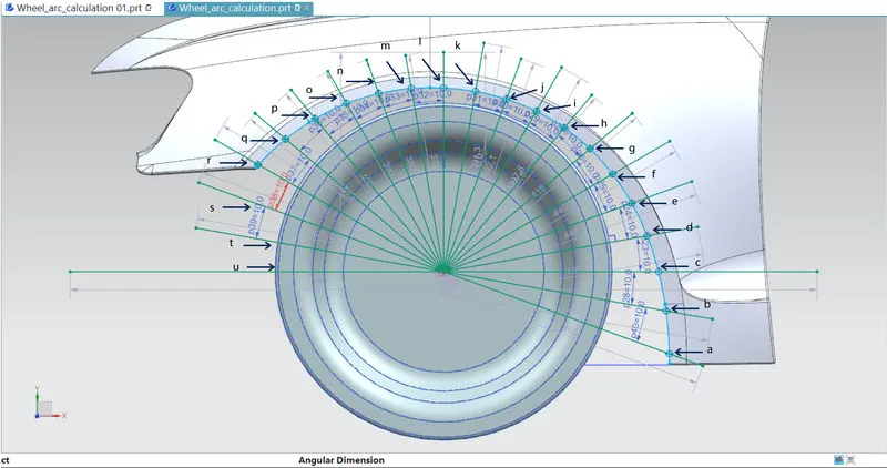
As per US regulation, the clearance between tyre and fender must be greater than 5mm. The projected points to be measured are at an angle 0° forward to 100° respectively. Thus, each position is divided into 10° and projected distances are measured at around 21 different points.
| MEASURED POINTS | A | B | C | D | E | F | G | H | I | J | K | L | M | N | O | P | Q | R | S | T | U |
| REQUIRED LENGTH | 5MM | 5MM | 5MM | 5MM | 5MM | 5MM | 5MM | 5MM | 5MM | 5MM | 5MM | 5MM | 5MM | 5MM | 5MM | 5MM | 5MM | 5MM | 5MM | 5MM | 5MM |
| ACTUAL LENGTH | -37.7789 | -29.5020 | -22.1070 | -15.4920 | -9.6151 | -4.4116 | -0.11394 | 3.4505 | 6.2030 | 8.1660 | 9.3918 | 9.9490 | 10.00 | 10.00 | 10.00 | 10.00 | 9.1753 | 5.7960 | - | - | - |
| REMARKS | FAIL | FAIL | FAIL | FAIL | FAIL | FAIL | FAIL | FAIL | PASS | PASS | PASS | PASS | PASS | PASS | PASS | PASS | PASS | PASS |
Conclusion
As per the table mentioned at points between ‘a’ to ‘u’ the value of clearance must be more than 5mm but, at several points from ‘A’ to ‘H’ the clearance value is in a negative clearance which denotes the interference of tyre and fender assembly. In which tyre protrudes outside the fender. Thus, design modification has to be done on the specified points in order to meet the US regulation requirements.