Fender Design - Wheel Arch Challenge
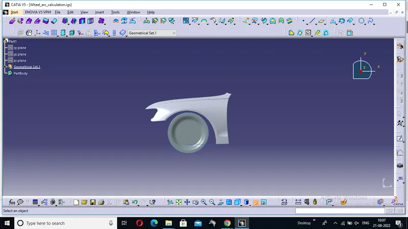
FENDER WHEEL ARCH CALCULATION USING CATIA V5
Aim:-
To calculate the Wheel Arc area and prove whether the car will pass the European standards or Not.
Wheel Arch:
- Wheel Arch is the semi-circular part of the fender positioned above the wheel of the vehicle.
- The design of Wheel arch of a fender should be such that it must shield wheels and protect both passengers’ compartment and pedestrians from projection of water, mud and stones.
- For the vehicle to has its use permit in different countries, the wheel arch of fenders must be compliant with the standards and regulations set by the respective countries.
The Standards commonly used are,
European Standards:
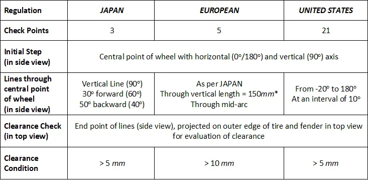
- At all five sections the clearance value should be greater than 10 mm.
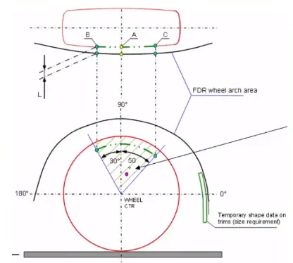
- Wheel guard requirement: The value of ‘a’ shall be more than 10 mm at a line 30˚ forward and 50˚rearward from the central vertical axis of wheel.
Japanese Standards:
- Clearance must be greater than 5 mm in all the three positions.
- Wheel guard requirement: The value of ‘a’ shall be more than 5 mm at a line 30˚ forward and 50˚ rearward from the central vertical axis of wheel.
Us Standards:
- All values should be greater than 5 mm.
- Wheel guard requirement: The value of ‘a’ shall be more than 5 mm 30˚ forward and 50˚ rearward from the central vertical axis of wheel.
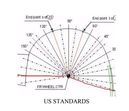
Wheel Arch Calculation:
This calculation will be done using European standards as per the instruction in the challenge to be followed.
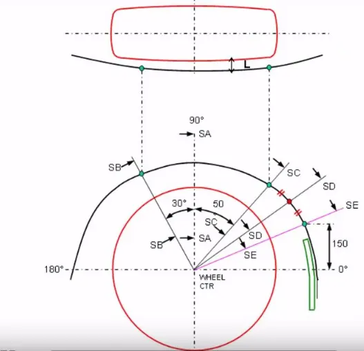
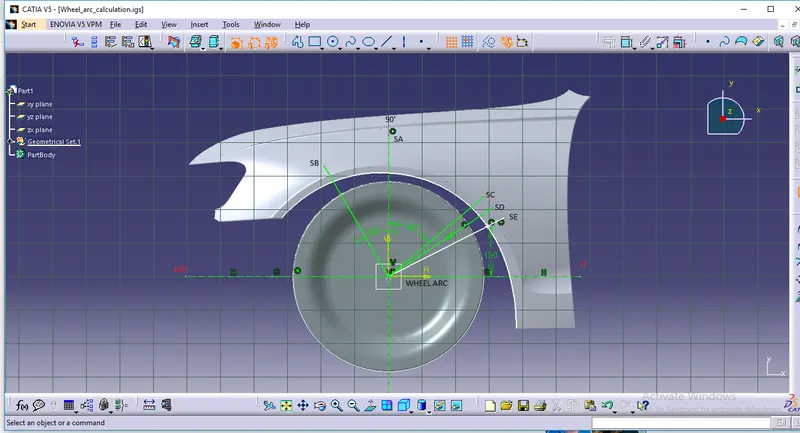
Procedure: The sketch is drawn on the wheel face and projected on the wheel arch at section SA, SB, SC, SD, and SE and then the clearance value at these section is measured.
- Take the outline of the wheel and the fender.
- Make the centre of the wheel circle.
- Draw horizontal and vertical perpendicular axes from the centre of the wheel circle.
- Draw lines at 30 degrees and 50 degrees from the centre.
- Make a point on the fender line at 150mm from the horizontal.
- Extend a line to this point from the centre.
- Then make a line that is exactly between the 50-degree line and the line made on the 150mm point.
- Measure the distances between the points on the wheel circle and fender curve. All of these should be greater than 10mm to satisfy the European regulations.
- Secondly, the horizontal distances from SA, SB, and SC points to the fender curve should be at least 10mm.
Check whether the design passes these conditions and conclude whether it can pass the European Regulations Requirement.
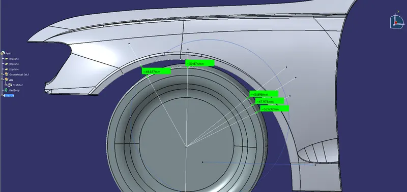
SA-SA
30.874>10
SB-SB
48.637>10
SC-SC
43.896>10
SD-SD
47.976>10
SE-SE
52.632>10
NOW LETS CALCULATE THE HORIZONTAL DISTANCE ;
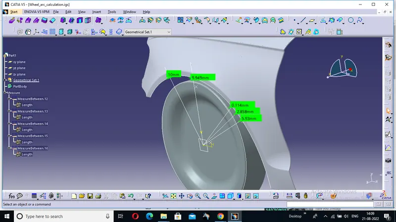
Distance between SA point and fender outer curve = 9.949 mm (fail)
Distance between SB point and fender outer curve = 10 mm (pass)
Distance between SC point and fender outer curve = 0.114 mm (fail)
Distance between SD point and fender outer curve = 2.858mm (fail)
Distance between SE point and fender outer curve = 5.93 mm (fail)
TABLE :
Distance Result
SA-SA 25.992>10 PASS
SB-SB 43.642>10 PASS
SC-SC 38.63 >10 PASS
SD-SD 42.662>10 PASS
SE-SE 47.625>10 PASS
From the outer curve of the fender to DISTANCE RESULT
SA - 9.949>10 - Fail
SB - 10>10 - Pass
SC - 0.114>10 - Fail
SD - 2.858>10 - Fail
SE - 5.93>10 - Fail
Conclusion:
- The given model doesnt satisfy the european standads on sections SA,SC,SD,SE the required clearance must be given in those sections. HENCE IT WILL REVERT BACK TO STYLYING .