Fender Design - Wheel Arch Challenge
Wheel Arch
- The wheel arch is the semicircular part positioned above the wheel of a vehicle.
- The most important body change was that the front wheel arch was cut higher into the fender.
- The Wheel Arch is designed such that it protects both the pedestrian and car cabin from mud, water rocks and other road spray
- Different countries have different wheel arch regulations in place, and the wheel arch design has to comply with them to be deemed usable in that country.
Fender Wheel Arch Regulations
US Regulations
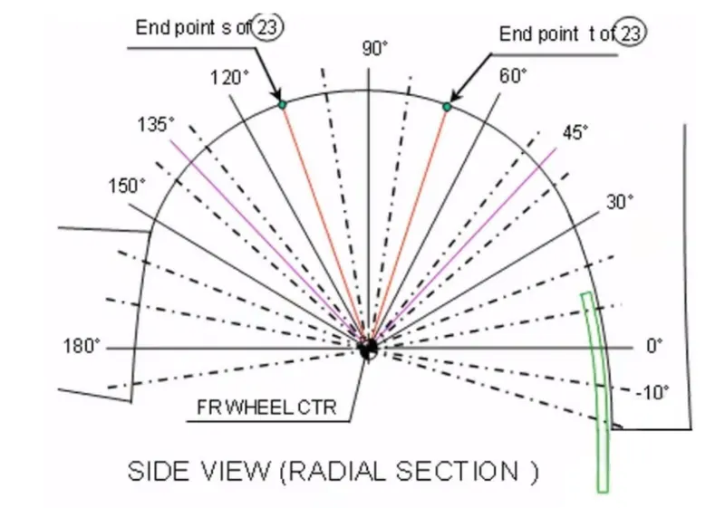
- Clearance ‘L’ is to be checked at all positions from -100° to 100° andThe value of L should be greater than 5mm
- The value of ‘a’ should be more than 5mm at line 30°and 50° from the central vertical axis of the wheel
European Regulations
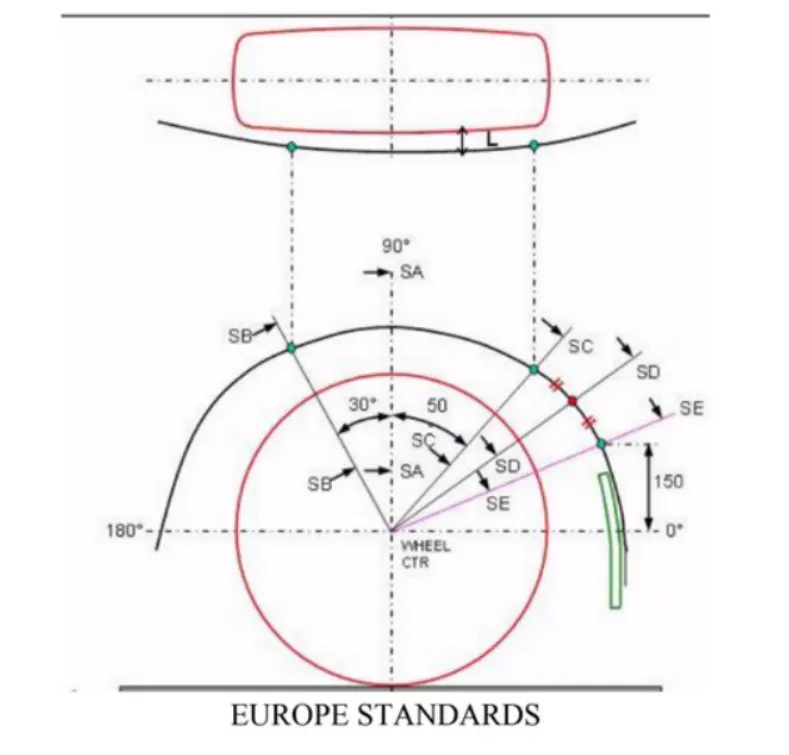
- The Clearance ‘L’ should be measured at sections SA-SA, SB-SB, SC-SC, SD-SD and SE-SE and At all the five sections the value of L should be greater than 10mm
- The value of ‘a’ should be more than 5mm at line 30° and 50° from the central vertical axis of the wheel.
Japan Regulations
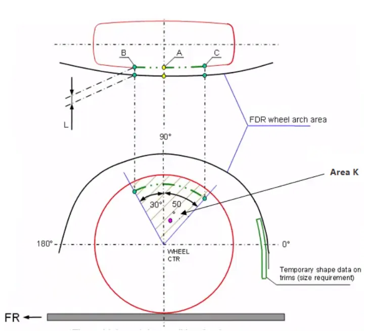
- The clearance ‘L’ for tire, hub, cap and fender is to be measured within area K and create clearance check chart to validate
- The value of L should be greater than 5mm at all positions
- The value of ‘a’ should be more than 5mm at line 30° and 50° from the central vertical axis of the wheel
Calculating the wheel arch area according to European Regulations
Procedure -
- A Datum Plane is created at the outermost face of the wheel
- wheel arch curve and outermost curve of the wheel is projected on the new Datum Plane
- A Horizontal line is drawn across the centre of the wheel mark it as reference
- A perpendicular line SA is dropped at the centre of the wheel
- Two lines SB and SC are created at 30° anti-clockwise of SA and 50° clockwise to SA respectively
- A point is created 150mm vertically above the centre line
- A line SE is drawn from the wheel centre and passes from the point created
- Another line SD is drawn from the centre of the wheel and in the middle of lines SC and SE
Obtaining the clearance "a" at the designated 5 points
1) Clearance 'a' at SA-SA
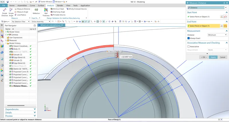
a = 32.5497 mm
2) Clearance 'a' at SB-SB
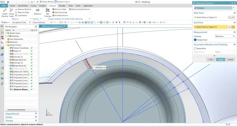
a = 49.6439 mm
3) Clearance 'a' at SC-SC
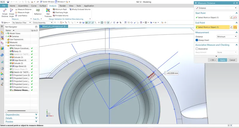
a = 43.3599 mm
4) Clearance 'a' at SD-SD
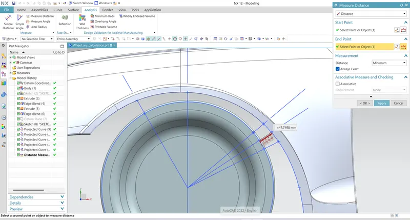
a = 47.7498mm
5) Clearance 'a' at SE-SE
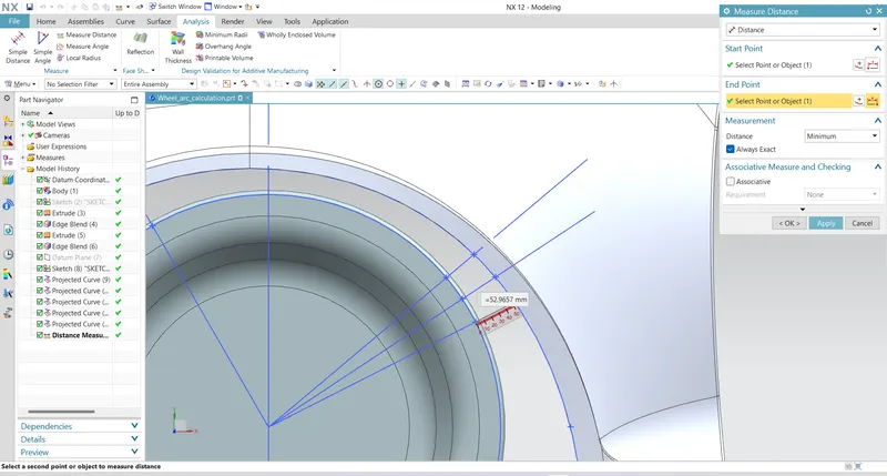
a = 52.9657
Obtaining the clearance "L" at the designated 5 points
1) Clearance 'L' at SA-SA
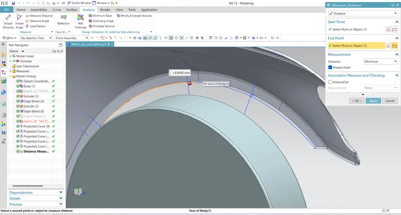
L = 9.9490 mm
2) Clearance 'L' at SB-SB
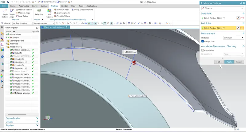
L = 10.0000
3) Clearance 'L' at SC-SC
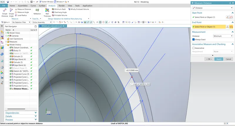
L = 0.1139 mm
4) Clearance 'L' at SD-SD
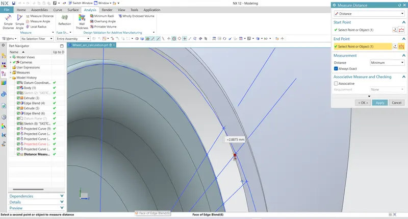
L =- 2.8875mm
5) Clearance 'L' at SE-SE
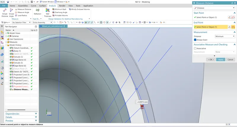
L =- 5.9973 mm
| SECTION | L (in mm) | RESULT | a (in mm) | RESULT |
| SA-SA | 9.9490 | Fail | 32.5497 | Pass |
| SB-SB | 10.0000 | Pass | 49.6439 | Pass |
| SC-SC | 0.1139 | Fail | 43.3599 | Pass |
| SD-SD | - 2.8875 | Fail | 47.7498 | Pass |
| SE-SE | - 5.9973 | Fail | 52.9657 | Pass |
From the above results we can conclude that the Fender does not pass the European Regulations, as the minimum clearance L between the Fennder Wheel Arch and Wheel for vehicle and pedestrian safety is 10mm and this design does not meet the requirement.