Fender Design - Wheel Arch Challenge
COURSE: Automotive Sheet Metal Design using Siemens NX CAD / CATIA V5
NAME: SRI RAGUL PREMKUMAR CHALLENGE: #4 Fender Design - Wheel Arch
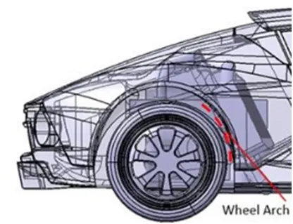
WHEEL ARCHES:
Firstly, they were used to reduce the amount of unwanted water and spray entering the wheel arches and disturbing the driven wheels from their operation.
This will lead to high pressure within the wheel arch along with a build-up of heat as the friction force between the tyre and the road builds up and converts somewhat to sound and heat energy. This will invariably increase the pressure of the tire itself, thus risking a possible blow-out if the pressure was allowed to reach over normal operating (normally 30-36 psi) and through drag reduction.
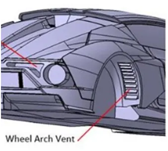
When is venturi used in the wheel of arches?
The Venturi Effect of the air entering and leaving the wheel arch and when air is accelerated through a deliberate constriction in the path of the airflow. A small but deliberate air inlet allowed the rear tires and brakes to stay cool and within their operating temperature ranges but with an outlet to reduce the build-up of unwanted high pressure that would cause inevitable tire blowouts in long endurance races.
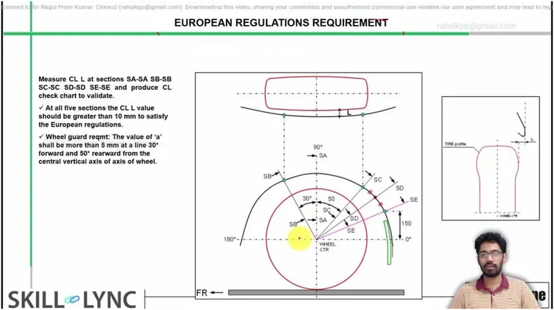
European Regulations requirements:
Using the wheel circle and fender curve as a guide, measure the distances between the points. According to European regulations, they should all be larger than 10mm.
A minimum distance of 5mm should be maintained between the SA, SB, SC, SD, and SE points, the fender curve. Analyze the design to determine if it meets these conditions and if it is capable of satisfying the European Regulations requirements.
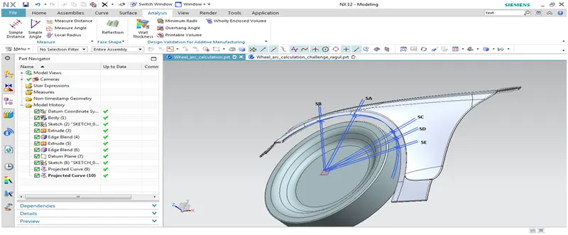
Procedure (NX Siemens):
- To create a wheel, take the outline of the wheel and the fender.
- The center of the wheel circle should be made.
- From the center of the wheel circle, draw horizontal and vertical perpendicular axes.
- From the center, draw lines at 30 degrees and 50 degrees.
- At 150mm from the horizontal, mark a point on the fender line.
- using the center as a reference, extend the line to this point.
- In the next step, draw a line that is exactly halfway between the 50-degree line and the 150mm point.
A value for clearance "L" can be obtained by using the following method:
- For a given wheel and fender at SB, measure “L” at SB - (10.00mm>=10.00mm) :
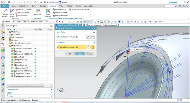
2. For a given wheel and fender at SA, measure “L” at SA - (10.00mm>=10.00mm) :
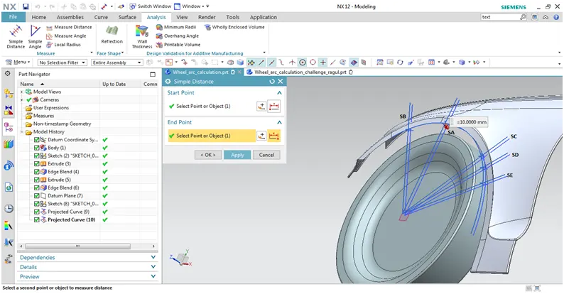
3. For a given wheel and fender at SC, measure “L” at SC - (09.00mm>=10.00mm) :
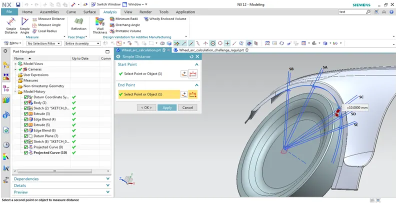
4. For a given wheel and fender at SD, measure “L” at SD - (10.00mm>=10.00mm) :
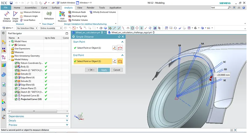
5. For a given wheel and fender at SE, measure “L” at SE - (10.00mm>=10.00mm) :
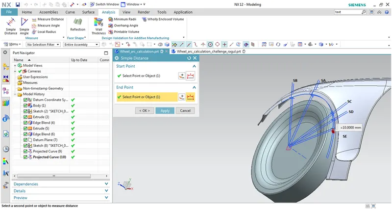
Table of value for clearance:
|
Measurement of "L" at |
Distance |
Result |
|
SB |
10.00mm |
Pass |
|
SA |
10.00mm |
Pass |
|
SC |
09.00mm |
Fail |
|
SD |
10.00mm |
Pass |
|
SE |
10.00mm |
Pass |
Conclusion:
From the above results obtained, the given fender is pass the European Regulations requirements.