Fender Design - Wheel Arch Challenge
FENDER DESIGN – WHEEL ARC CHALLENGE
Now after the design of the hood, here comes the next challenge for us to calculate the wheel arc area. The wheel arc area is nothing but the amount of the space i.e the tolerance provided to the wheel end point from the fender end point in the inward direction.
Now as we all know that each of the OEM design the components considering some standards which has their own regulations of designing the part or component across the globe.
We have learnt about the Japan Standards, European Standards and USA Standards for the wheel arc design calculations. The difference between them is just the tolerance provided to the wheel, and the points from where the tolerance is calculated.
Now we are provided with the front wheel fender part along with the wheel as shown in the figure below.
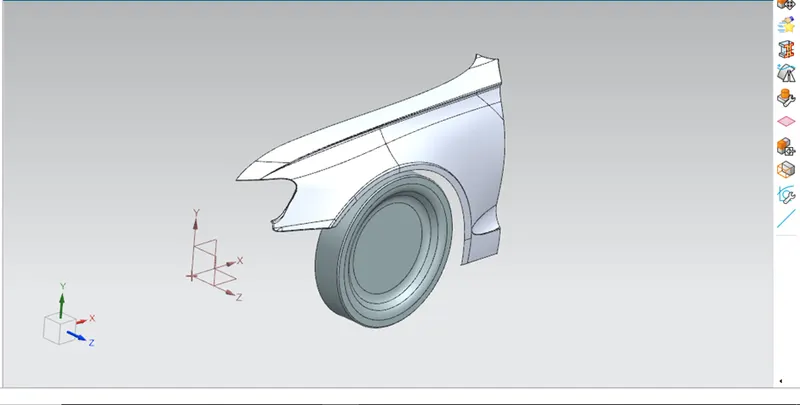
Our task is to initially study the European standards and then prove by calculating that this fender design is following the European regulations/standards or not.
Now initially we need to study the European standards about the wheel arc calculations.
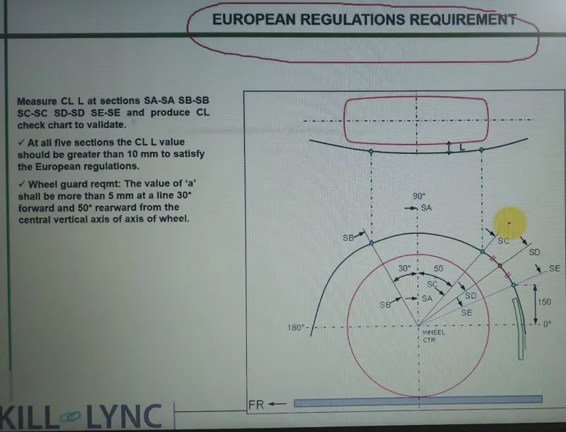
According to the European standards the tolerance should be about greater than or equal to 10mm. And to calculate the tolerance we initially need to draw the sketch wherein we need to define the points at certain angle as shown in the figure below.
|
SR .NO |
POINTS |
ANGLE |
|
1. |
SB |
30 Degree from center. |
|
2. |
SA |
90 Degree reference line. |
|
3. |
SC |
50 Degree to right from center. |
|
4. |
SE |
150mm above from the center line . |
|
5. |
SD |
This is the midpoint of point SC and SE. |
So as shown in the above figure and table we need to sketch and locate this points on to the wheel.
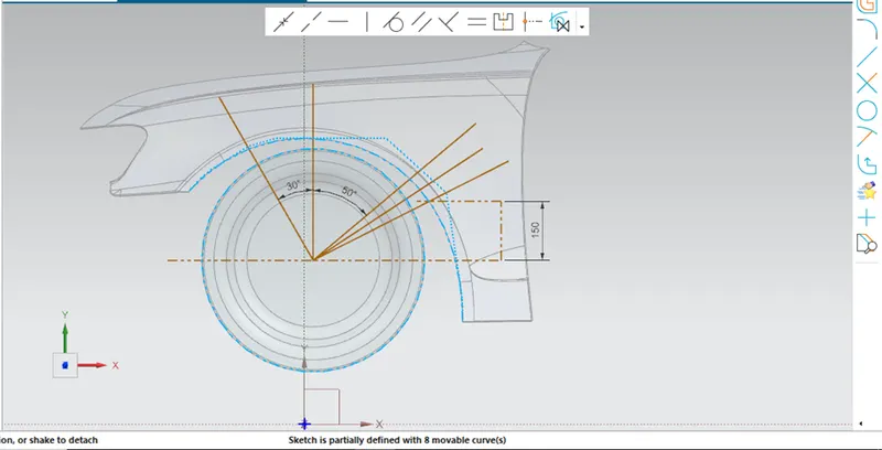
Now as we have just sketched the lines as per the given standards we need to locate the points on to the intersection of lines and wheel arc and then project the points on to the fender arc. And finally calculate the distance and give the proof that the above given fender is following the European standards or not.
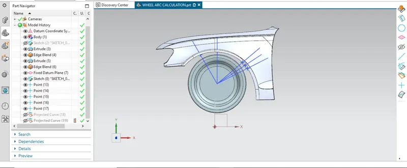
3D points located.
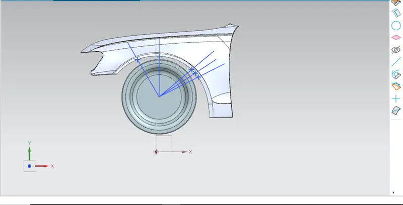
Points projected on to the fender wheel arc.
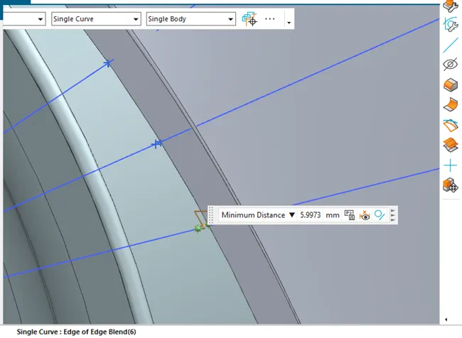
Now as we have projected the points let’s calculate the L i.e the length between these two points.
The calculated data is given in the form of the table.
Here in total the four points is located.
The distance should be minimum of 10mm.
|
Sr no. |
Points |
Distance (L) |
Images |
|
1. |
SB |
10mm |
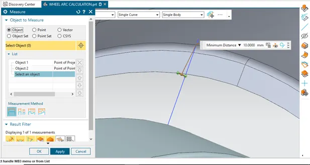 |
|
2. |
SA |
9.94mm |
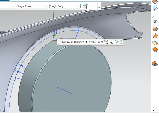 |
|
3. |
SC |
0.11mm |
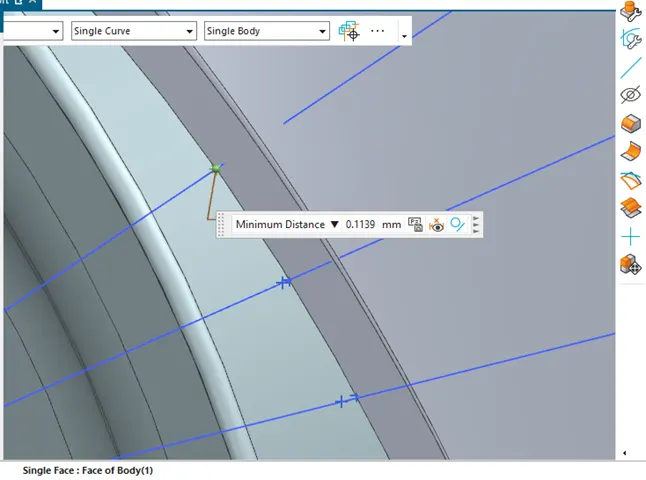 |
|
4. |
SE |
5.99mm |
 |
|
5. |
SD |
2.91mm |
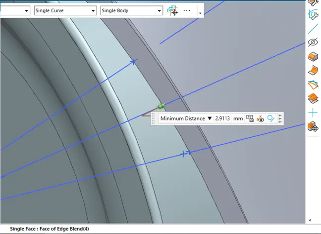 |
So now if we compare the values we get to known only the point SB has the tolerance length of 10mm and rest all the points SC, SE, SD, SA are below 10mm i.e less than 10mm.
So now to conclude it, we can say that this fender design is not matching the European design standards for the fender. And we need to inform the styling team, to have changes in the fender design.