Fender Design - Wheel Arch Challenge
FENDER DESIGN-WHEEL ARC CHALLENGE
AIM:To calculate the Wheel Arch gap at required points and check whether the car passes the European standard or not.
FENDER
- Fender is the side closing component for the engine compartment. It's major role is to avoid chipping sand, small stones and mud particles inside the engine compartment when the wheels rotate.
- Normally automobiles have four fenders, one over each wheel. For vehicles with a narrow car body that exposes the tire, the fender is an exposed curve over the top of the tire. For wide body vehicles that cover the tire, the fender forms the wheel well surrounding the tire, and is not directly visible from above the car body.
- Wheel wells tend to be much larger than the diameter of the tire, because they do not move with the tire suspension and consequently they should not come in contact with the wheel when the vehicle is at its most suspended position
WHEEL ARC
- The wheel arch is the semicircular part positioned above the wheel of a vehicle. The most important body change was that the front wheel arch was cut higher into the fender. Corrosion had occurred around the splash plate at the back of the wheel arch.
-
The shaped part of the bodywork of a car or other vehicle that allows the wheel to be accessed, and in the case of front wheels, enable them to be steered. Wheel arch is an semi-circular area in fender, which houses the wheel well.
- The second function is to protect the car from the sticky materials, such as mud, may adhere to the smooth outer tire surface, while smooth loose objects, such as stones, can become temporarily embedded in the tread grooves as the tire rolls over the ground.
- These materials can be ejected from the surface of the tire at high velocity as the tire imparts kinetic energy to the attached objects. For a vehicle moving forward, the top of the tire is rotating upward and forward and can throw objects into the air at other vehicles or pedestrians in front of the vehicle.So wheel arc prevent that from happening.
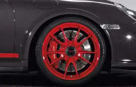
WHEEL ARC REGULATIONS:
For the design of wheel arc and fender there is different standards available to ensure maximum safety and performance,which are the following;
- JAPAN REGULATION
- US REGULATION
- EUROPEAN REGULATION
Japan Regulations:
The requirements are as follows;
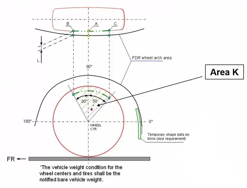
- Measure clearance L of tire ,hub, cap & fender in three different positions within area K and produce clearance check chart to validate.
- Clearance must be greater than 5 mm in all the three positions.
- Wheel guard requirement: The value of 'a' shall be more than 5 mm at a line 30" forward and 50 rearward from the central vertical axis of axis of wheel.
US Regulations
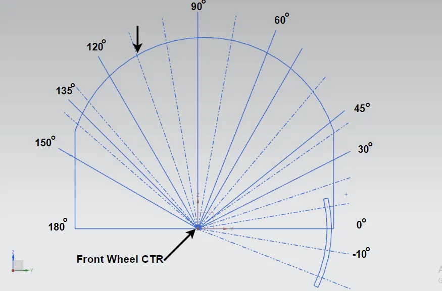
- Clearance ‘L’ is to be checked at all positions from -100° to 100° and create clearance check chart to validate
- The value of L should be greater than 5mm to satisfy the regulations
- Wheel guard requirement: The value of ‘a’ should be more than 5mm at line 30° forward and 50° rearwards from the central vertical axis of the wheel.
European Regulations
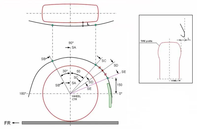
- The Clearance ‘L’ should be measured at sections SA-SA, SB-SB, SC-SC, SD-SD and SE-SE and create clearance check chart to validate
- At all the five sections the value of L should be greater than 10mm to satisfy the European Regulations
- Wheel guard requirement: The value of ‘a’ should be more than 5mm at line 30° forward and 50° rearwards from the central vertical axis of the wheel.
OBJECTIVE:
To check the wheel arc and fender clearances according to the european regulations requirements and to make a conclusion on whether the given model is compatible or not.
PROCEDURE:
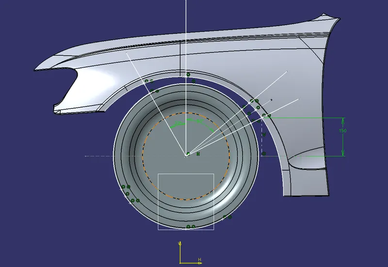
- Create a datum plane on the extreme most part of the wheel from the bottom view using the option through planar curve
- Then create a point that is in the centre of the wheel circle in the same plane
- Then create a perpendicular line from the point (SA)
- Then create a line 30 degree to left which is our (SB) and then create a line that is 50 degree to the right of the perpendicular line which is our (SC)
- Then create a point on the fender arc which is at a perpendicular distance of 150mm from the horizontal through the centre point. And through that point create a line which is our (SE)
- Then using bisecting line method draw a line between SC&SE which will be our SD
- Using project 3D element project both the extreme part of the wheel from the top view and also the extreme edge of the fender
- Now create points on the intersections between the projected circle and semi circle to each line
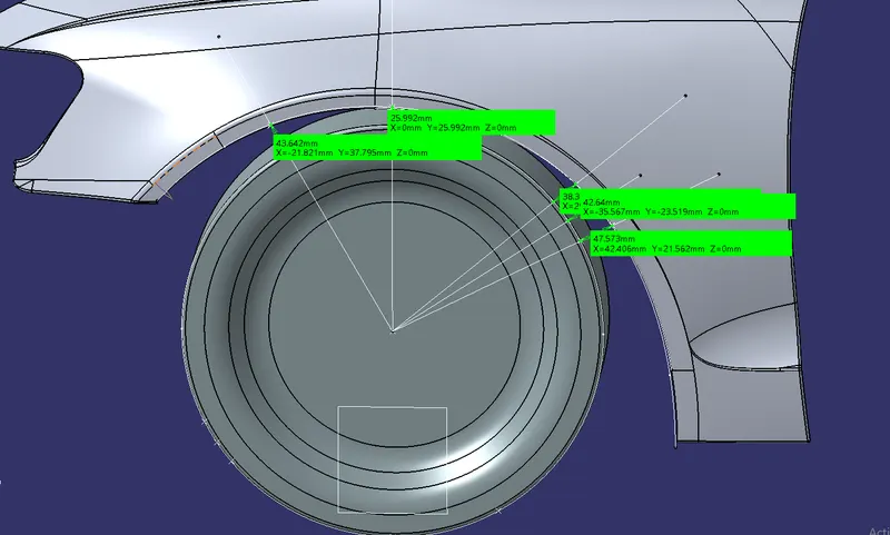
- Distance between these intersection points on each line will be its "a" value
- Now project the points on the fender projection to the fender surface
- Distance between those two points is the 'L' value
'a' values for each line;
'L' values for each line;
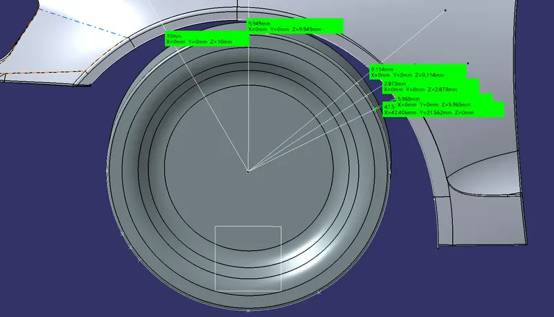
TABLE FOR "L" VALUES
MINIMUM VALUE FOR L MUST BE 10MM
| SECTION | VALUE OBTAINED | RESULT |
| SA | 10.000 | PASS |
| SB | 9..949 | FAIL |
| SC | 0.114 | FAIL |
| SD | 2.873 | FAIL |
| SE | 5.965 | FAIL |
TABLE FOR "a" VALUES
MINIMUM VALUE FOR "a" IS 5MM
| SECTION | OBTAINED VALUE | RESULT |
| SA | 43.642 | PASS |
| SB | 25.992 | PASS |
| SC | 38.36 | PASS |
| SD | 42.64 | PASS |
| SE | 47.573 | PASS |
CONCLUSION
It is clear that the fender design does not pass the requirments set by the european regulations for the "L" value for the parts except SA.That means the fender design is not fit as per the european guidelines and it should be changed by the styling team in order to pass the requirements set by the european guidelines