Fender Design - Wheel Arch Challenge
Challenge:
Calculate the Wheel Arch gap at the required points and check whether the car passes the European standard.
Fender
Fender is the American English term for the part of an automobile, motorcycle, or other vehicle body that frames a wheel well (the fender underside).
Its primary purpose is to prevent sand, mud, rocks, liquids, and another road spray from being thrown into the air by the rotating tire. Fenders are typically rigid and can be damaged by contact with the road surface.
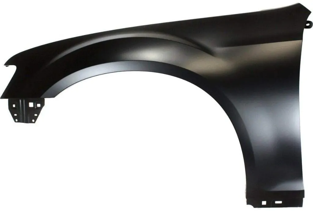
Fig 1: Fender
Sticky materials, such as mud, may adhere to the smooth outer tire surface, while smooth loose objects, such as stones, can become temporarily embedded in the tread grooves as the tire rolls over the ground. These materials can be ejected from the surface of the tire at high velocity as the tire imparts kinetic energy to the attached objects. For a vehicle moving forward, the top of the tire is rotating upward and forward and can throw objects into the air at other vehicles or pedestrians in front of the vehicle.
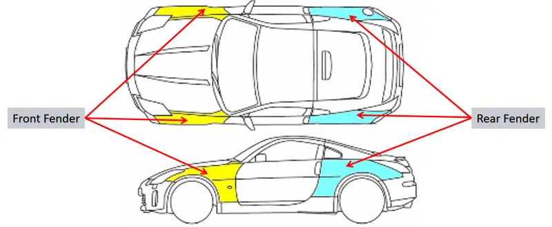
Fig 2: Front & Rear Fender
The above image illustrates the position & types of fenders. Generally, a car will have 4 fenders each per wheel.
Wheel Arch
The wheel arch is the semicircular part positioned above the wheel of a vehicle. The most important body change was that the front wheel arch was cut higher into the fender. Corrosion had occurred around the splash plate at the back of the wheel arch. The car has big, high-definition headlights that extend to the wheel arch.
The design of the wheel arch of the fender should be such that it must shield wheels and protect both passengers and pedestrians from the projection of stone and mud.
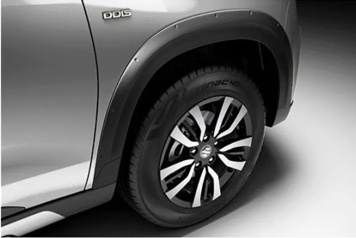
Fig 3: Fender Wheel Arch
Fender Wheel Arch Regulations
Different regions of the world have Fender Wheel Arch Regulations
Japan Regulations :
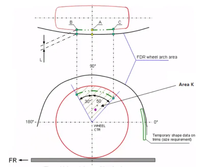
Fig 4: Japan Fender Wheel Arch Regulations
- In this method as shown in the above fig on the wheel schematic two lines will be drawn with an angle to the vertical line from the center of the wheel.
- Projection of all the points will be observed from the top side of the car.
- The clearance "L" for the tire, hub, cap, and fender is to be measured within area K, and create a clearance check chart to validate.
- The value of L should be greater than 5mm at all positions.
- Wheel guard requirement: The value of "a" should be more than 5mm at line 30 degrees forward and 50 degrees rearwards from the central vertical axis of the wheel.
European Regulations :
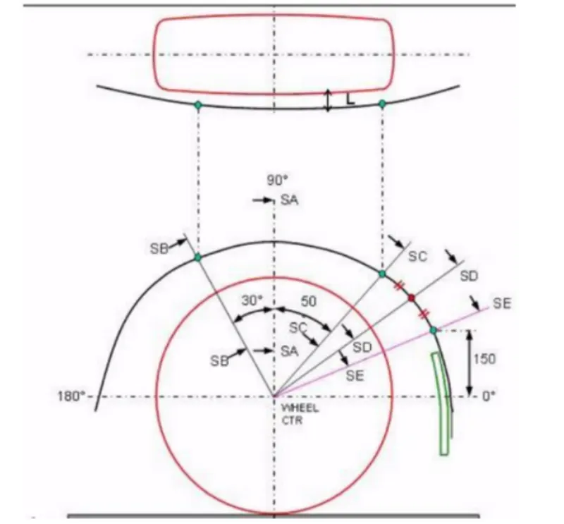
Fig 5: European Fender Wheel Arch Regulations
- In this method in addition the to Japan method two more lines will be drawn & projections will be observed.
- The clearance "L" should be measured at sections SA-SA, SB-SB, SC-SC, SD-SD, and SE-SE and create a clearance check chart to validate.
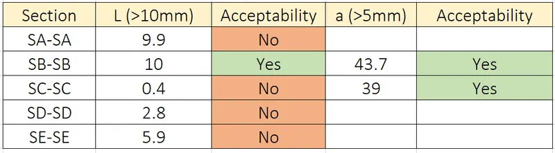
- At all five sections the value of L should be greater than 10mm to satisfy European Regulations.
- Wheel guard requirement: The value of "a" should be more than 5mm at line 30 degrees forward and 50 degrees rearwards from the central vertical axis of the wheel.
US Regulations :
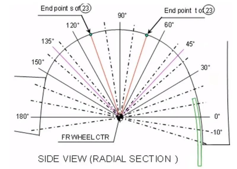
Fig 6: US Fender Wheel Arch Regulations
- In this method angular lines will be drawn at every 10 degrees.
- Clearance "L" is to be checked at all positions from -20 degrees to 180 degrees and create a clearance check chart to validate.
- The value of L should be greater than 5mm to satisfy the regulations.
- Wheel guard requirement: The value of "a" should be more than 5mm at line 30 degrees forward and 50 degrees rearwards from the central vertical axis of the wheel.
Calculations of wheel Arch area as per European Regulations
Step 1: A datum plane is created at the utmost of the wheel face.
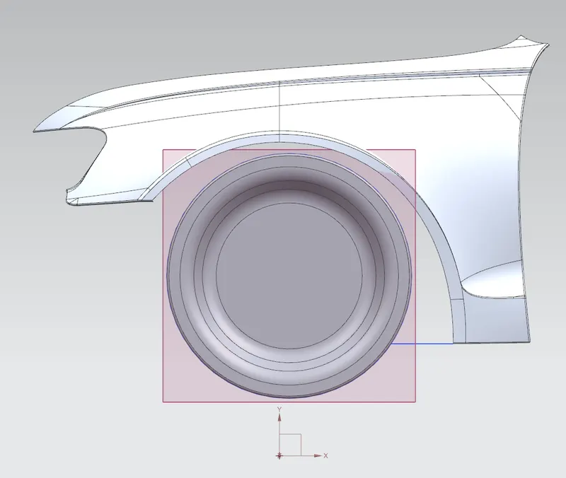
Fig 7: Datum plane
Step 2: A sketch was made as per European Regulations on the datum plate created.
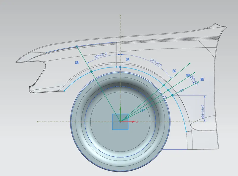
Fig 8: Sketch as per European Regulations
Step 3: Measured the distance at all the locations.
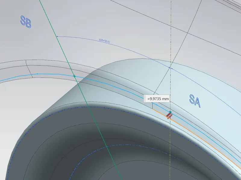
Fig 9: L value at Section SA-SA
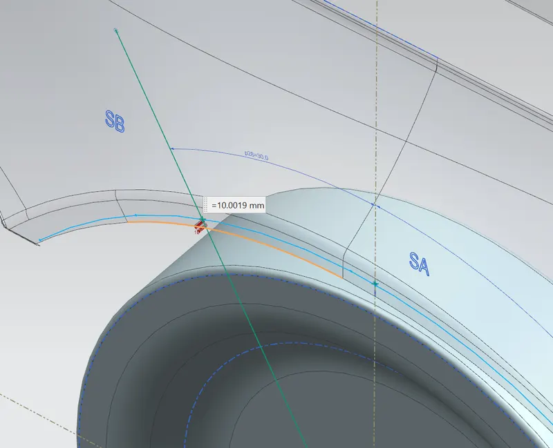
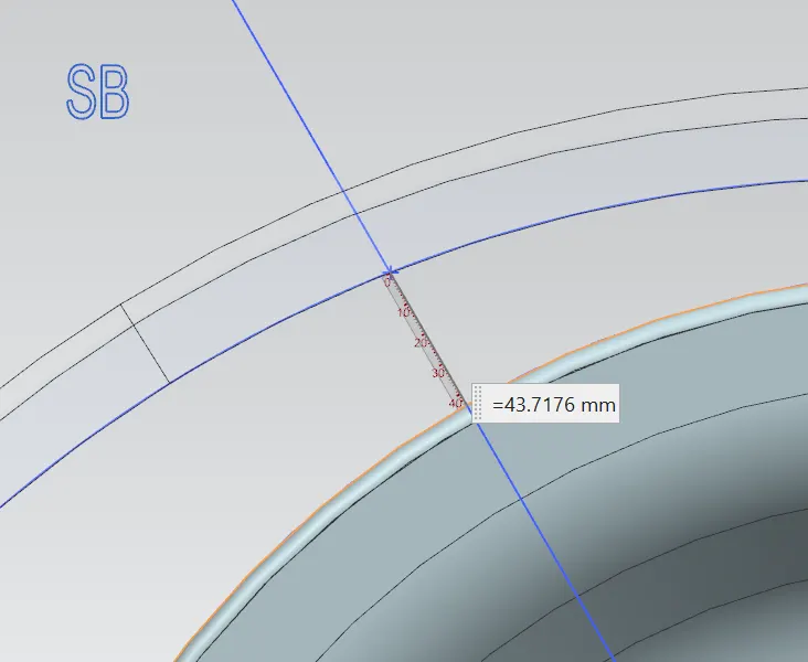
Fig 10: L value & 'a' value at Section SB-SB
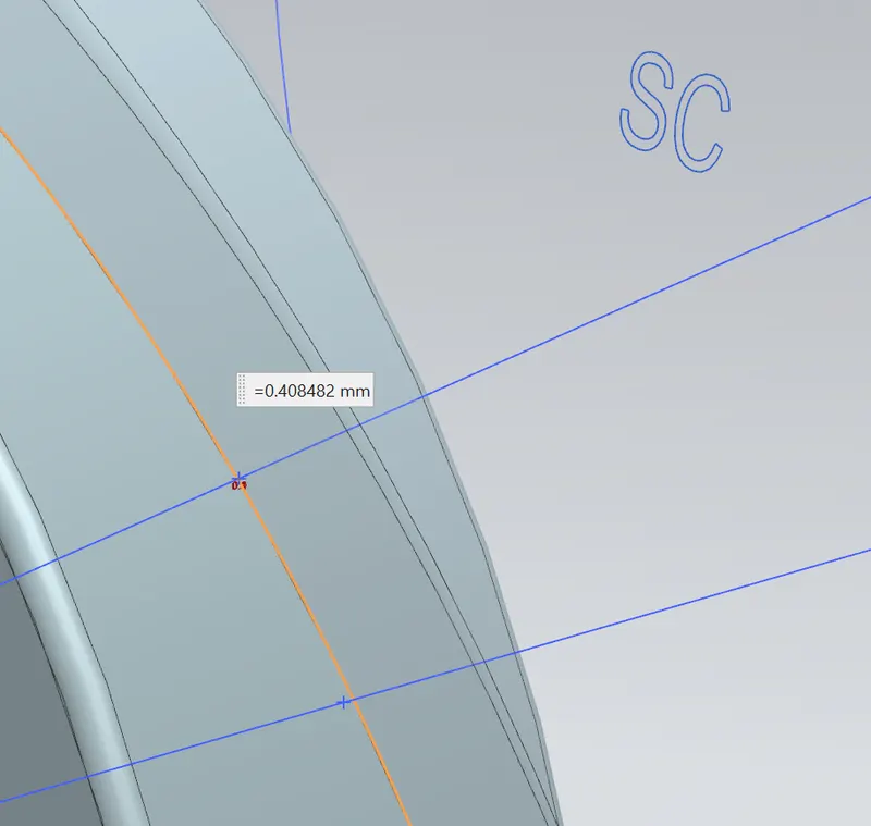
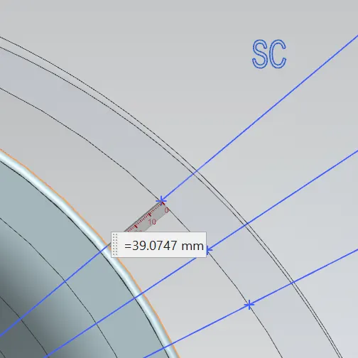
Fig 11: L value & 'a' value at Section SC-SC
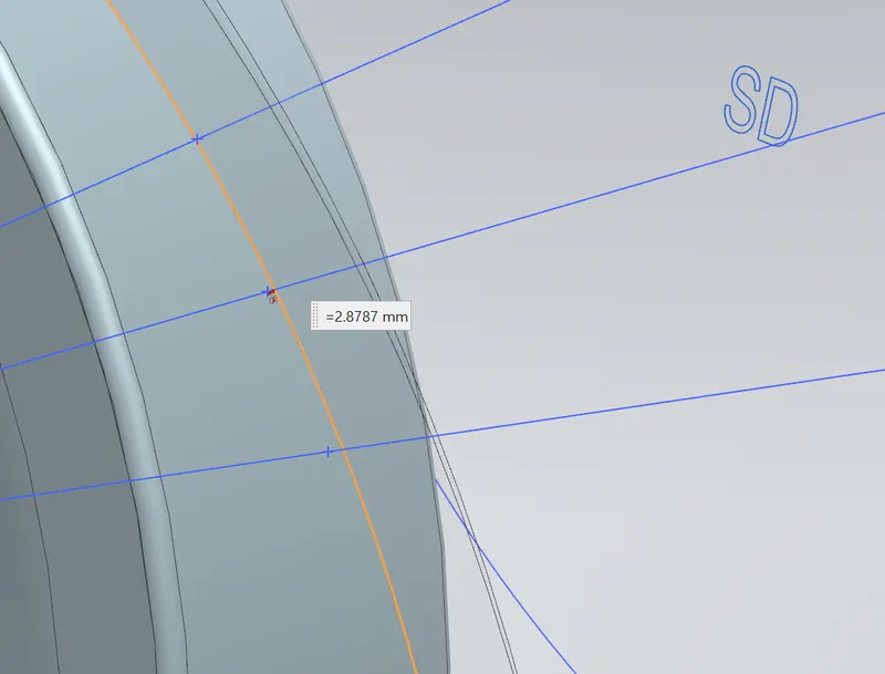
Fig 12: L value at Section SD-SD
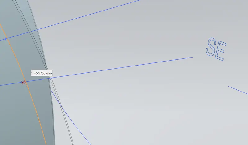
Fig 13: L value at Section SE-SE
Results
Conclusion:
After all the results observations, it is concluded that the given model is not having enough clearance at SC-SC, SD-SD, & SE-SE sections. The model is not acceptable.