Fender Design
Objective: Using the European Standards calculate the wheel arch area and prove whether the car will pass the standards or not.
Introduction:
Fender or Wheel guard panel prevents sand, mud, rocks, and other particles from the road which is picked by the tire to the engine compartment and also prevents injuries to the pedestrians when the tire rotates.
Fender is the US English word for the wheel guard panel.
Most passenger cars have four fenders, one over each tire. The car when looked at from the top the tire exposed outside the body is completely covered by the fender.
There are two types of Fender
- Full bumper type
- Half Bumper type
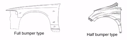
Full bumper type is avoided in recent days because the scrappage of material is high whereas in half bumper type there is a high possibility to reduce the scrappage.
Two half bumper types can be produced with a slight increase in the dimensions of the blank which is used to create the full bumper type.
This method also allows using of plastic as the metal usage is reduced which in turn increases the performance of the car as the weight is reduced.
Mounting Points:
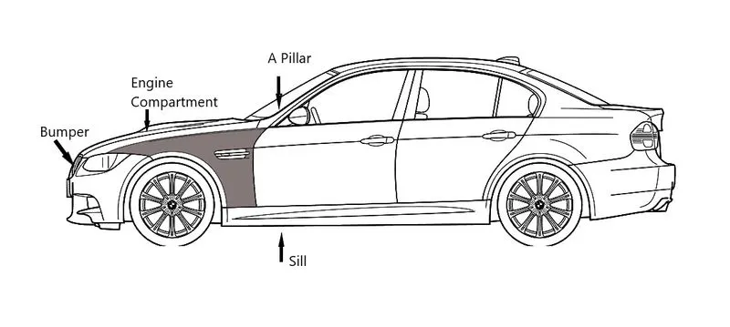
The fender is mounted with 5 mounting points:
- BIW
- A-Pillar
- Sill
- Bumper
- Drip Area
- Cowl
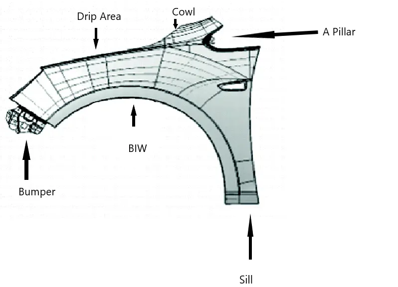
The drip area is where the fender comes in contact with the engine compartment. This is the major and important mounting area that has common design consideration which is followed by all OEMs and the mounting points are decided based on the packaging of the components under the hood.
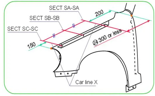
Design Considerations of the Drip area.
The drip area should be located such that one end of the drip area should be 300mm or less from the cowl mounting region and the other end of the drip area should be 150mm from the headlamp mounting region.
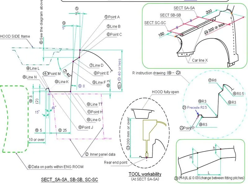
The design of the drip is done by following the master section given above. The 3 `degree` angle is given to order to satisfy the tooling axis clearance.
Line D is given at an angle of 45`degree` from the horizontal extended to a particular length because when there will be a gap between fender and hood and when seen through the gap the engine compartment and other mounting points should not be visible.
The total height of the drip area should be around 35 to 40mm so that the tool has enough clearance to work on the mounting points.
At the end of the drip area, there is an undercut given which adds strength to the drip area. It is to be checked that the drip area is 10 mm or more away from the engine room.
The total height of the drip area should no exceed more than 60mm which leads to the spring-back effect. Hence the total height should be below 40mm.
The cowl is the area where the wiper motor is mounted.
A-Pillar is the near-vertical support structure in the car which gives structural support to the car body welded between windshield and front doors on both sides of the vehicle.
Sill is a horizontal support structure connecting between the front and rear support structure to which closure components (doors), B Pillar, and Fender are mounted to it.
A bumper is a structure attached to or integrated with the front and rear ends of a motor vehicle to absorb impact in a minor collision, ideally minimizing repair costs.
The highlighted region is the fender.
Fasteners are used to fasten the fender as fasteners are covered by the outer body. Hence use of fasteners does not affect the aesthetic look of the car.
The mounting holes should have a minimum of a 5mm gap between the fillet edge and the circumference of the circle.
Design of Fender
Inputs
Class A Surface
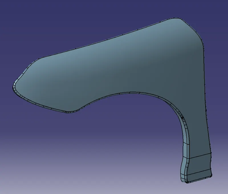
Master Section
Surface modeled with Mountings
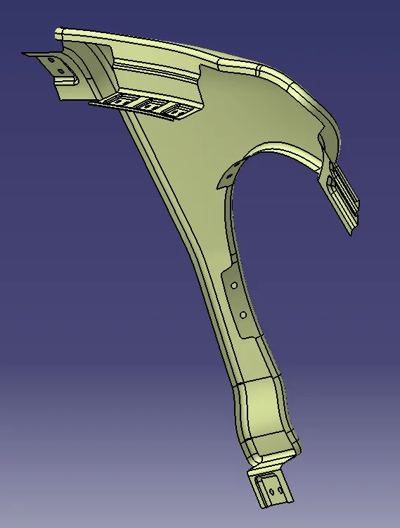
Thickened body with 0.75 mm thickness
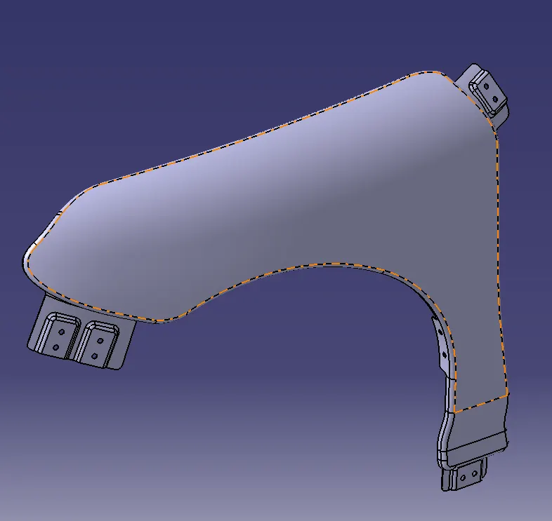
Mounting Points:
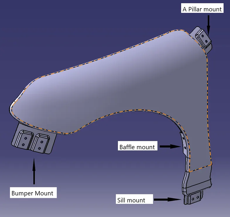
Top View
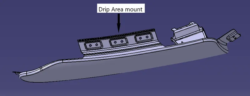
Side View
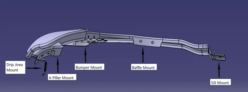
Conclusion:
1. The fender drip area is designed according to the master given considering the engineering aspects.
2. The required number of fender mounting points are designed.